background image

SRS-ZR7

2

1. 

SERVICING  NOTES 

 .............................................   3

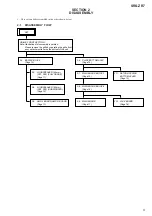
2. DISASSEMBLY

2-1. Disassembly 

Flow 

...........................................................   9

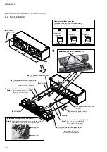
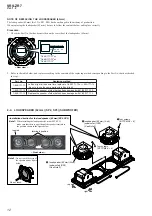
2-2. Baf

fl

 e Block ....................................................................   10

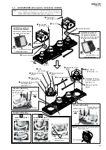
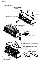
2-3.  Loudspeaker (45 mm) (SP1, SP4) (Full Range) .............   11
2-4.  Loudspeaker (62 mm) (SP2, SP3) (Subwoofer) .............   12
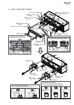
2-5.  AMP-L Board, AMP-R Board ........................................   13
2-6. Plate 

Bottom 

Assy 

...........................................................  14

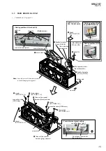
2-7.  MAIN Board Block-1 .....................................................   15
2-8.  MAIN Board Block-2 .....................................................   16
2-9. MAIN 

Board 

...................................................................  17

2-10. JACK Board ....................................................................   18
2-11.  Return Spring, Bottom Lever ..........................................   19

3. 

TEST  MODE 

 ............................................................   20

4. 

EXPLODED  VIEWS

4-1.  Speaker Unit Section ......................................................   22
4-2.  Plate Bottom Section ......................................................   23
4-3.  MAIN Board Section ......................................................   24
4-4.  Cabinet Block Section ....................................................   25

5. ACCESSORIES 

 .......................................................   26

TABLE  OF  CONTENTS

Notes on the AC adaptor

Ş

When connecting or disconnecting the AC 
adaptor, turn off the unit beforehand. Otherwise, 
it may cause malfunction.

Ş

Use only the supplied AC adaptor. To avoid 
damaging the unit, do not use any other AC 
adaptor.

Polarity of the plug

Ş

Plug the AC adaptor into a nearby AC outlet. In 
the case of a problem, unplug it from the AC 
outlet immediately.

Ş

Do not install the AC adaptor in a confined space, 
such as a bookcase or built-in cabinet.

Laboratories. Dolby and the double-D symbol are 
trademarks of Dolby Laboratories.

** For DTS patents, see http://patents.dts.com. 

Manufactured under license from DTS, Inc. DTS, the 
symbol & DTS and the Symbol together are 
registered trademarks, and DTS 2.0 Channel is a 
trademark of DTS, Inc. c DTS, Inc. All Rights 
Reserved.

Ş

The BLUETOOTH® word mark and logos are 
owned by the Bluetooth SIG, Inc. and any use of 
such marks by Sony Corporation is under license. 
Other trademarks and trade names are those of 
their respective owners.

Ş

Google Play and Android are trademarks of 
Google Inc.

Ş

Google Cast and the Google Cast Badge are 
trademarks of Google Inc.

Ş

“Xperia” and “Xperia Tablet” are trademarks of 
Sony Mobile Communications AB.

Ş

LDAC™ and LDAC logo are trademarks of Sony 
Corporation.

Ş

DLNA™, the DLNA Logo and DLNA CERTIFIED™ 
are trademarks, service marks, or certification 
marks of the Digital Living Network Alliance.

Ş

This product incorporates Spotify software which 
is subject to 3rd party licenses found here: 
https://developer.spotify.com/esdk-third-party-
licenses/

Ş

Spotify and Spotify logos are trademarks of the 
Spotify Group.

Ş

The unit names and product names indicated in 
this document are generally the trademarks or 
registered trademarks of the manufacturer.  
™ and ® marks are omitted in this document.

On copyrights

Ş

This product is protected by certain intellectual 
property rights of Microsoft Corporation. Use or 
distribution of such technology outside of this 
product is prohibited without a license from 
Microsoft or an authorized Microsoft subsidiary.

Ş

iPhone and iPod touch are trademarks of Apple 
Inc., registered in the U.S. and other countries. 
“Made for iPod” and “Made for iPhone” mean 
that an electronic accessory has been designed 
to connect specifically to iPod or iPhone, 
respectively,  and has been certified by the 
developer to meet Apple performance standards. 
Apple is not responsible for the operation of this 
unit or its compliance with safety and regulatory 
standards. Please note that the use of this 
accessory with iPod or iPhone may affect 
wireless performance. 
App Store is a service mark of Apple Inc.

Ş

” is a mark of the Wi-Fi Alliance.

Ş

Wi-Fi®, Wi-Fi Protected Access® and Wi-Fi 
Alliance® are registered marks of the Wi-Fi 
Alliance.

Ş

Wi-Fi CERTIFIED™, WPA™, WPA2™ and Wi-Fi 
Protected Setup™ are marks of the Wi-Fi 
Alliance.

Ş

MPEG Layer-3 audio coding technology and 
patents licensed from Fraunhofer IIS and 
Thomson.

Ş

The N-Mark is a trademark or registered 
trademark of NFC Forum, Inc. in the United States 
and in other countries.

Ş

This unit incorporates High-Definition Multimedia 
Interface (HDMI™) technology. The terms HDMI 
and HDMI High-Definition Multimedia Interface, 
and the HDMI Logo are trademarks or registered 
trademarks of HDMI Licensing LLC in the United 
States and other countries.

Ş

This system incorporates Dolby* Digital and the 
DTS** Digital Surround System. This system 
incorporates Dolby* Digital.

*  Manufactured under license from Dolby 

SAFETY-RELATED  COMPONENT  WARNING!

COMPONENTS  IDENTIFIED  BY  MARK  

0

  OR  DOTTED  LINE  

WITH  MARK  

0

  ON  THE  SCHEMATIC  DIAGRAMS  AND  IN  

THE  PARTS  LIST  ARE  CRITICAL  TO  SAFE  OPERATION.
REPLACE  THESE  COMPONENTS  WITH  SONY  PARTS 


WHOSE  PART  NUMBERS  APPEAR  AS  SHOWN  IN  THIS  
MANUAL  OR  IN  SUPPLEMENTS  PUBLISHED  BY  SONY.

ATTENTION  AU  COMPOSANT  AYANT  RAPPORT  

À  LA  SÉCURITÉ!

LES  COMPOSANTS  IDENTIFIÉS  PAR  UNE  MARQUE  

0

  SUR  

LES  DIAGRAMMES  SCHÉMATIQUES  ET  LA  LISTE  DES  
PIÈCES  SONT  CRITIQUES  POUR  LA  SÉCURITÉ  DE  FONC-
TIONNEMENT.  NE  REMPLACER  CES  COMPOSANTS  QUE  
PAR  DES  PIÈCES  SONY  DONT  LES  NUMÉROS  SONT  DON-
NÉS  DANS  CE  MANUEL  OU  DANS  LES  SUPPLÉMENTS  
PUBLIÉS  PAR  SONY.

Ver. 1.2

Summary of Contents for SRS-ZR7

Page 1: ...rage Class MSC USB B port B You can connect a compatible device such as a PC etc to this unit using a USB cable not supplied Supported format PCM 44 1 48 88 2 96 176 4 192 kHz 16 24 32bit DSD DSF DSDIFF 2 8 5 6 MHz 1 bit Compatibility with all encoding writing software recording devices and recording media cannot be guaranteed Approx 300 mm 93 mm 86 mm 11 7 8 in x 3 3 4 in x 3 1 2 in w h d For cus...

Page 2: ...ademarks or registered trademarks of the manufacturer and marks are omitted in this document On copyrights Ş This product is protected by certain intellectual property rights of Microsoft Corporation Use or distribution of such technology outside of this product is prohibited without a license from Microsoft or an authorized Microsoft subsidiary Ş iPhone and iPod touch are trademarks of Apple Inc ...

Page 3: ...ortant information for servicing Be sure to read this section before repairing the unit CHECKING METHOD OF NETWORK WIRELESS LAN WIRED LAN CONNECTION When the MAIN board is replaced be sure to perform the connec tion check of network wireless LAN wired LAN 1 Checking Method of Wireless LAN Connection Required item Wireless router with the Wi Fi Protected Setup WPS button Procedure 1 Place the unit ...

Page 4: ...INK indicator begins to flash in pink Wait about a minute until the LINK indicator lights up in pink When the connection is completed the LINK indicator changes from flashing to staying lit in pink Hint 4 Note When you connect the speaker to a network for the first time after purchase or after you initialize the speaker the BLUETOOTH Network standby function is turned on automatically When you con...

Page 5: ... side of this unit MAC1 MAC address of wired LAN MAC2 MAC address of wireless LAN Note of the MAC address change The MAC address of this unit was changed along with this repair Please set it again if you are using the MAC address filtering function of access point device of connection destination MAC address is displayed on the bottom side of this unit MAC1 MAC address of wired LAN MAC2 MAC addres...

Page 6: ...SRS ZR7 6 MEMO ...

Page 7: ...r to the Help Guide DLNA Digital Living Network Alli ance for the re setup method Request of the DLNA re setup The DTCP IP ID of this unit was changed along with this repair When registration of client devices to the DLNA server device is not automatic it is necessary to register this unit into a server again Please refer to the Help Guide DLNA Digital Living Network Alli ance for the re setup met...

Page 8: ...SRS ZR7 8 MEMO ...
Page 9: ...BOARD Page 17 2 10 JACK BOARD Page 18 2 11 RETURN SPRING BOTTOM LEVER Page 19 2 6 PLATE BOTTOM ASSY Page 14 2 3 LOUDSPEAKER 45 mm SP1 SP4 FULL RANGE Page 11 2 4 LOUDSPEAKER 62 mm SP2 SP3 SUBWOOFER Page 12 2 5 AMP L BOARD AMP R BOARD Page 13 GRILLE FRONT SECTION Note Illustration of disassembly is omitted Please remove the grille by operating the grille front assy detachment lever on the bottom of ...

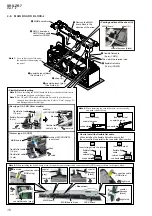
Page 10: ...oofer terminal narrow black Note 1 The terminal is locked firmly Please remove the terminal carefully not to be damaged 5 L ch subwoofer terminal wide white Note 1 The terminal is locked firmly Please remove the terminal carefully not to be damaged 4 L ch speaker cable connector CN804 caulking part speaker unit QVWDOODWLRQ GLUHFWLRQ IRU WKH VSHDNHU ZLUH Note 2 When installing the speaker wire towa...

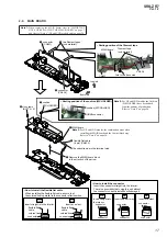
Page 11: ...aker L ch full range SP1 speaker cable 7 loudspeaker 45 mm R ch full range SP4 See Note 1 2 terminal terminal 2 acoustic absorbent 1 four screws BTTP M2 6 u 8 3 box block 3 box block cushion QVWDOODWLRQ SRVLWLRQ RI WKH DFRXVWLF DEVRUEHQW Insert the acoustic absorbent into inside of the box block box block for L ch Do not touch right side top side outside inside inside outside top side URQW LQQHU Y...

Page 12: ...f No SP1 SP4 has been changed in the midway of production When replacing the loudspeaker 45 mm be sure to follow the contents below and replace correctly Procedure 1 Check the Part No that has been written on the rear side of the loudspeaker 45 mm 1 859 171 11 or 1 859 171 12 or 1 859 171 13 Xxxxxxxxxxxxxxxx XX XX XX XX Malaysia Rear view 2 Refer to the table below and replace according to the con...

Page 13: ...WDOO WKH FRQQHFWRU Insert the connector straight into the interior There is a possibility that using this unit without the connector correctly installed will damage it 2 AMP R board connector CN851 9 AMP R board connector CN854 hole 3 AMP L board connector CN802 AMP L board AMP R board 7 AMP L board connector CN805 6 saranet cushion 8 saranet cushion 5 AMP L board connector CN801 1 two sheet B she...

Page 14: ...er 5 Insert your finger in the crevice between the plate bottom assy and the cabinet and while peeling off the adhesive surface remove the plate bottom assy carefully old plate bottom serial label When replacing the plate bottom assy peel the serial label on the plate bottom carefully and stick the serial label to the new plate bottom Refer to the figure below 6 plate bottom assy Note 3 When remov...

Page 15: ...KHHW 3DVWLQJ SRVLWLRQ RI WKH VKHHW 27720 The opposite side is the terminal side connection cable GND strap connection cable GND strap rib screw hole 5 three screws BTTP M2 6 u 8 6 Take out the coaxial harness gray outward coaxial harness gray 6 Take out the coaxial harness black outward coaxial harness black This side is the terminal side RWWRP YLHZ right side RD LDO KDUQHVV JUD VHWWLQJ rib Do not...

Page 16: ...ible flat cable 4 pin have been changed from the midway of production Refer to Note on page 25 and distinguish new former type coaxial harness Insert vertically OK Insert at a slant NG connector coaxial harness connector Insert straight into the interior OK Insert at a slant NG RZ WR LQVWDOO WKH IOH LEOH IODW FDEOH When installing the flexible flat cable ensure that the colored line is parallel to...

Page 17: ...nector after insertion colored line flexible flat cable connector colored line flexible flat cable connector Insert only part way Insert straight into the interior connector Insert at a slant connector connector connector connector connector 2 NG NG RZ WR LQVWDOO WKH FRQQHFWRU Insert the connector straight into the interior There is a possibility that using this unit without the connector correctl...

Page 18: ...ter insertion colored line flexible flat cable connector colored line flexible flat cable connector Insert only part way Insert straight into the interior connector Insert at a slant connector connector connector connector connector 2 NG NG RZ WR LQVWDOO WKH FRQQHFWRU Insert the connector straight into the interior There is a possibility that using this unit without the connector correctly install...

Page 19: ...ed fully OK Return spring is floating 1 boss of cabinet boss of cabinet return spring bottom lever return spring bottom side front side 3DVWLQJ SRVLWLRQ RI WKH VKHHW PLF KROG 1 two tapping screws P2 u 5 2 retain plate notch notch boss 4 return spring return spring 3 sheet mic hold sheet mic hold hook 6 bottom lever boss hole 5 Draw the bottom lever out from the hole front side ...

Page 20: ... three colors lights up in white 5 Each time STEREO PAIR button is pressed the color of LINK and NETWORK indicators repeatedly changes in following order light up light up Color of LINK indicator Three color LED One color LED Red LED Green LED Blue LED Green LED White ON ON ON ON Blue green OFF ON ON ON Pink Violet ON OFF ON OFF Blue OFF OFF ON OFF Orange Yellow ON ON OFF OFF Green OFF ON OFF ON R...

Page 21: ...uch the button The minor version upper in the system firmware version dis play mode is shown Touch the button The minor version lower in the system firmware version dis play mode is shown The system firmware version is shown by the blinking frequency of the PAIRING 1 indicator blinking Example When the system firmware version is 1 23 When touching the FUNCTION button the PAIRING 1 in dicator blink...

Page 22: ...2593 406 1 GRILL FRONT W ASSY SV for White 2 4 586 233 11 SCREW 3X10 HEX 3 X 2593 403 1 BAFFLE BLOCK E ASSY SV Including Cushion Except US CND 3 X 2593 404 1 BAFFLE BLOCK U ASSY SV Including Cushion US CND 4 4 218 253 32 SCREW M2 6 BTTP L 8 mm 5 3 287 010 01 SHEET B SP1 1 859 171 12 LOUDSPEAKER 45 mm 171 12 Full Range L ch See Note SP1 1 859 171 13 LOUDSPEAKER 45 mm 171 13 Full Range L ch See Note...

Page 23: ...PLATE BOTTOM W AU ASSY SV for White Including Sheet Adhesive sheet AUS 54 X 2593 678 1 PLATE BOTTOM B KR ASSY SV for Black Including Sheet Adhesive sheet KR 54 X 2593 679 1 PLATE BOTTOM W KR ASSY SV for White Including Sheet Adhesive sheet KR 54 X 2593 680 1 PLATE BOTTOM B SP ASSY SV for Black Including Sheet Adhesive sheet SP5 54 X 2593 681 1 PLATE BOTTOM W SP ASSY SV for White Including Sheet Ad...

Page 24: ...S HOLDER Ref No 106 the combination occur when installing the Cabinet block assy Ref No CAB1 on page 25 and the Complete MAIN board Ref No 101 When replacing the Complete MAIN board Ref No 101 confirm the presence or absence of the Cushion WS HOLDER refer to the following notes JACK board component side cushion WS HOLDER Note 2 US and Canadian models only This part has been added from the midway o...

Page 25: ...MP L BOARD COMPLETE US CND AR TH LA 153 A 2144 092 A AMP L BOARD COMPLETE AEP RU UK HK SP5 TW KR AUS CH 154 3 287 010 01 SHEET B 155 3 080 206 21 SCREW TAPPING P2 L 5 mm 156 4 594 704 01 SPRING RETURN 157 4 583 059 02 LEVER BOTTOM 158 4 477 465 21 HI RES LABEL 159 3 381 709 31 CUSHION SARANET AEP RU UK HK SP5 TW KR AUS CAB1 X 2593 399 2 CABINET BLOCK B J ASSY SV for Black AR TH LA CH CAB1 X 2593 4...

Page 26: ...AEP UK HK 4 592 063 34 MANUAL INSTRUCTION FINNISH AEP UK HK 4 592 063 44 MANUAL INSTRUCTION PORTUGUESE AEP UK HK 4 592 063 54 MANUAL INSTRUCTION NORWEGIAN AEP UK HK 4 592 063 61 MANUAL INSTRUCTION RUSSIAN RU 4 592 063 81 MANUAL INSTRUCTION KAZAKH RU 4 592 063 92 MANUAL INSTRUCTION ENGLISH SP5 AR LA AUS 4 592 064 11 MANUAL INSTRUCTION SIMPLIFIED CHINESE CH 4 592 064 21 MANUAL INSTRUCTION KOREAN KR ...

Page 27: ... components identified by mark 0 or dotted line with mark 0 are critical for safety Replace only with part number specified Les composants identifiés par une marque 0 sont critiques pour la sécurité Ne les remplacer que par une pièce por tant le numéro spécifié 0 501 1 492 523 22 AC ADAPTER VGP AC19V75 2PIN US CND AR TH LA CH 0 502 A 2144 739 A AC ADAPTER ASSY VGP AC19V75 with FERRITE CORE AEP RU ...

Page 28: ...EAKER 45 mm Ref No SP1 SP4 and Addition of Note for Replacement Change of Part No for FOOT Ref No 53 Addition of Note for Replacement of PLATE BOTTOM ASSY Ref No 54 COMPLETE MAIN BOARD Ref No 101 COMPLETE JACK BOARD Ref No 102 and CABINET BLOCK ASSY Ref No CAB1 for US and CND models Addition of Part for CUSHION WS HOLDER Ref No 106 US and CND models Change of Part No for INSTRUCTION MANUAL AEP UK ...

Reviews: