3-73
SRW-5000/5500
F1
F2
F3
F4
DIAG
ALT
F5
F6
F7
F8
F9
F10
NVRAM
CTL
CAPSTN
GAIN
EXIT
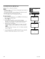
ALT SERVO ADJUST
RF SWITCHING POS.
Press SET key.
ALT SERVO ADJUST
Set
HR2-1B
Alignment tape
ALT SERVO ADJUST
RF SWITCHING POS.
Auto Adjusting. . .
PG :
ALT SERVO ADJUST
RF SWITCHING POS.
Auto Adjust Complete
PG : 2514
T REEL
GAIN
TENSN
OFFSET
2.
[SET]
3. Insert the
alignment tape
RF SW
POS SR
RF SW
POS HD
[F5]
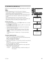
(RF SW POS SR) Key
Performs the RF switching position adjustment.
m
.
Perform this adjustment in 59.94 Hz mode. This adjustment does not need to be
adjusted in the other modes.
.
Use the alignment tape HR2-1B for the adjustment. The adjustment cannot be
performed correctly with a non-specified cassette tape.
.
Rewind the alignment tape to the tape beginning in advance.
Execution Procedure
1.
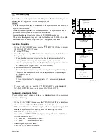
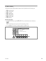
In the ALT SERVO ADJUST menu, press the
[F5]
(RF SW POS SR) key to
display the RF SW POSITION menu.
2.
Press the
[SET]
key.
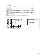
3.
Insert the alignment tape HR2-1B rewound to the tape beginning.
.
Adjustment is executed automatically when the alignment tape is inserted.
The message “Auto Adjusting...” is displayed during the adjustment.
4.
Confirm the result of the adjustment.
.
When the adjustment is completed normally, the message “Auto Adjust
Complete” is displayed, and the alignment tape is ejected automatically.
n
If “Auto Adjust Failure” is displayed, refer to “For Automatic Adjustment
Failure” on page 3-75.
5.
To save the adjusted data, press the
[F1]
(NVRAM CTL) key to display the
NV-RAM CONTROL menu, and execute “SAVE ALL DATA”.
SRW-5500


