background image

5-20

SRW-5000/5500

PSW3 

x

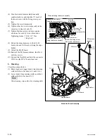
 8

Viddeo head
cleaner assembly

Cleaning roller

A

Height determining
plate

2

1

3

H

H

H

Hours label

Full-erase head

Installation

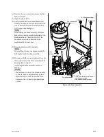
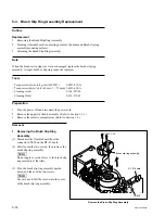
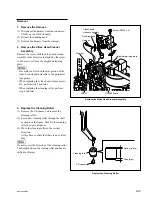
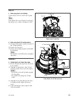
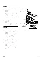
4. Attach the Video Head Cleaner

Assembly

(1) Insert the cleaning roller from the clearance

between the height determining plate and the

full-erase head.

n

Be careful not to touch the arm portion of the
video head cleaner assembly to the peripheral

tape guides.

(2) Align the two pins of the video head cleaner

assembly to the two holes of the height

determining plate.

(3) Tighten the screw while moving the video

head cleaner assembly in the direction
indicated by the arrow A (counterclockwise).

(4) Fill in the hours of the cleaning roller re-

placement on the hours label sticked on the

video head cleaner assembly.

Attach the Video Head Cleaner Assembly

Summary of Contents for SRW-5000

Page 1: ... DIGITAL VIDEOCASSETTE RECORDER SRW 5000 SRW 5500 FORMAT CONVERTER BOARD HKSR 5001 DIGITAL BETACAM PROCESSOR BOARD HKSR 5002 RGB PROCESSOR BOARD HKSR 5003 MAINTENANCE MANUAL Volume 1 1st Edition Revised 2 ...

Page 2: ... power from an outlet on the rack please make sure that the rack does not overload the supply circuit 2 Providing protective earth When this product is installed in a rack and is supplied power from an outlet on the rack please confirm that the outlet is provided with a suitable protective earth connection 3 Internal air ambient temperature of the rack When this product is installed in a rack plea...

Page 3: ... kun batteri som anbefalt av apparatfabrikanten Brukt batteri returneres apparatleverandøren VARNING Explosionsfara vid felaktigt batteribyte Använd samma batterityp eller en likvärdig typ som rekommenderas av apparattillverkaren Kassera använt batteri enligt gällande föreskrifter VAROITUS Paristo voi räjähtää jos se on virheellisesti asennettu Vaihda paristo ainoastaan laitevalmistajan suosittele...

Page 4: ......

Page 5: ... Main Parts 1 11 1 8 1 Printed Circuit Boards and Power Supply Unit Locations 1 11 1 8 2 Main Mechanical Part Locations 1 13 1 9 Function and Location of Sensors 1 14 1 10 System of Cassettes 1 16 1 11 Taking Out the Cassette in Tape Slacking 1 18 1 12 Removing Reattaching Plug in Board 1 20 1 13 Function of LEDs on Circuit Boards 1 22 1 14 Description of Switch Functions 1 27 1 15 Circuit Protect...

Page 6: ...oard 1 55 1 25 18 HP 110 Board 1 55 1 25 19 HPR 8 Board HPR 8A Board 1 55 1 25 20 IRC 5 Board IRC 5A Board 1 55 1 25 21 KY 526 527 465 Board 1 56 1 25 22 LED 386 Board 1 56 1 25 23 LP 81 Board 1 56 1 25 24 MB 964 Board 1 56 1 25 25 PC 70 Board 1 56 1 25 26 PTC 101 Board 1 56 1 25 27 PTC 102 Board 1 56 1 25 28 PTC 99 Board 1 56 1 25 29 RX 80 Board 1 56 1 25 30 SE 606A Board 1 57 1 25 31 SS 95 Board...

Page 7: ...4 1 Overview 3 64 3 4 2 SERVO ADJUST Menu 3 65 3 4 3 DT SAT ADJUST Menu 3 76 3 4 4 SD OUT ADJUST Menu 3 83 3 4 5 RF ADJUST Menu 3 84 4 Periodic Maintenance and Inspection 4 1 Periodic Maintenance 4 1 4 1 1 Index 4 1 4 1 2 Periodic Replacement and Check Item Table 4 2 4 1 3 Hours Meter 4 4 4 2 Cleaning 4 5 4 2 1 Cleaning using Cleaning Tape 4 5 4 2 2 General Information for Cleaning using Cleaning ...

Page 8: ...el Motor Assembly Replacement 5 46 5 14 Reel Shift Motor Replacement 5 52 5 15 Reel Shift Gear Replacement 5 54 5 16 Tape Guide Replacement 5 56 5 16 1 S Plate Assembly Replacement 5 57 5 17 Gear Box Assembly Replacement 5 59 5 18 Threading Ring Assembly Replacement 5 61 5 19 S Tension Regulator Assembly Replacement 5 67 5 20 T Tension Regulator Assembly Replacement 5 70 5 21 T Drawer Assembly Rep...

Page 9: ...tment Flow Chart 6 1 6 1 2 Precautions 6 1 6 1 3 Parts Location of the Tape Path System 6 2 6 1 4 Cassette Compartment 6 2 6 1 5 Cassette Tape 6 3 6 1 6 Tracking Control 6 3 6 1 7 Preparation 6 4 6 1 8 Alignment Tapes 6 4 6 1 9 Locking Compound 6 4 6 2 Video Tracking Check 6 5 6 3 Tracking Adjustment at the Tape Entrance Side 6 13 6 4 Tracking Adjustment at the Tape Exit Side 6 18 6 5 CTL Head Hei...

Page 10: ...the AT Head 7 11 7 3 1 Adjustment Overview 7 11 7 3 2 Preparation 7 13 7 3 3 Time Code System Adjustment 7 15 7 3 4 CUE PB System Adjustment CUE 13 AE 31H Boards 7 17 7 3 5 CUE REC System Adjustment CUE 13 AE 31H Boards SRW 5500 only 7 19 8 Electrical Alignment 8 1 Electrical Alignment Overview 8 1 8 1 1 Precautions 8 1 8 1 2 Outline of Electrical Alignment 8 1 8 1 3 Set the System 8 2 8 2 Power S...

Page 11: ...ystem Alignment VPR 79 Board 8 27 8 6 1 Adjustment Overview 8 27 8 6 2 SD SDI Free running Frequency Adjustment 8 28 8 6 3 SD Video Output Adjustment 525 59 94 Hz Output 8 29 8 6 4 SD Video Output Adjustment 625 50 Hz Output 8 30 8 7 HD Video System Alignment HPR 8 HPR 8A Board 8 31 8 7 1 Adjustment Overview 8 31 8 7 2 INT 74 MHz Frequency Adjustment 8 32 8 7 3 HD REF Output Adjustment 8 33 8 8 LT...

Page 12: ......

Page 13: ...cation and operation and installation of this unit Installation Manual Supplied with this unit This manual describes the information on installing this unit Protocol Manual of Remote 9 pin Connector available on request This manual explains the protocol for controlling the VTR via the RS 422A 9 pin serial remote If this manual is required please contact your local Sony Sales Office Service Center ...

Page 14: ...ains each menu of the maintenance mode Section 4 Periodic Maintenance and Inspection Explains the recommended periodic maintenance and the cleaning procedure Section 5 Replacement of Main Parts Explains the replacement of mechanical parts power supply unit and circuit boards Section 6 Tape Path Alignment Explains the tape path alignment after replacement of parts that are described in Section 5 Se...

Page 15: ...rieving information on Semiconductor Pin Assignments CD ROM which is available separately Please refer to this section together with the Semiconductor Pin Assignments CD ROM Section 3 Block Diagrams Describes the block diagrams of overall and each board Section 4 Board Layouts Describes the board layouts for the unit Section 1 Schematic Diagrams and Frame Wiring Describes the schematic diagrams an...

Page 16: ......

Page 17: ... a specified cleaning cassette tape If not the video heads may be abrasive or damaged If the head clogging is not solved using a cleaning cassette tape use cleaning cloth For the cleaning using a cleaning cloth clean according to the procedure of 4 2 3 Rotary Heads Cleaning and 4 2 4 Tape Running Surface of Upper Drum Cleaning after confirming the cautions and preparation in 4 2 2 General Informat...

Page 18: ...ching install in the reverse order of removal n Tighten the fixing screws as following torque Tightening torque 120 x 10 _2 N m 12 0 kgf cm 1 3 2 Removing Reattaching Bottom Plate 1 Place the unit with the side facing down 2 Remove the two screws securing the bottom plate 3 Slide the bottom plate in the arrow A direction to unhook the four hooks 4 Remove the bottom plate in the arrow B direction W...

Page 19: ...ngs shown in the fugure and then remove the front panel in the arrow direction When reattaching install in the reverse order of removal n When reattaching the front panel press it tightly against the chassis in parallel n Use of screws other than specified will cause damage of the internal mechanism Be sure to use the specified screws 1 3 3 Removing Reattaching Side Panels and Front Panel 1 Remove...

Page 20: ...o remove 5 Remove the bead tie and open the edge holder n This step is not required when both option HKSR 5001 and HKSR 5003 are installed 6 Dicconnect the all coaxial cables connected to the plug in boards n Hold the plug to remove the coaxial cables in discon necting the coaxial cables from the connector on the boards Refer to Section 1 12 7 Remove the coaxial cables from the guide rail L 8 Remo...

Page 21: ...pper lide front asssembly and upper lid rear assembly Refer to Section 1 3 1 2 Remove the SS 95 board and APR 62 board Refer to Section 1 12 3 Remove the eight screws shown in the figure 4 Push out the connector panel assembly from inside the unit in the arrow direction and disconnect the connec tor connected to the mother board When reattaching install in the reverse order of removal n Push in po...

Page 22: ...ght and left the gear or part may come off Place the cassette compartment with the cassette lid up or with cassette compartment positioning legs down If it is put with the cassette lid down the flexible card wire board might be damaged 1 5 Removing Reattaching Cassette Compartment m Turn off the power before starting the removal installa tion The cassette compartment cannot be removed with the cas...

Page 23: ... right and left If unnecessary force is applied to the right and left the gear or part may come off 7 Press the portions C of the cassette compartment as shown in the figure and then fit the four positioning legs into the four positioning holes in the mechanical deck Be sure to attach the cassette compartment while pressing down the portion D of the SC Guide Assem bly by fingers If not the cassett...

Page 24: ...e visible from your side before tightening the screws 1 6 Removing Reattaching Lower Control Panel Unit Removal 1 Turn off the power of the VTR 2 If the lock plates are attached remove the two screws and remove the lock plates 3 Push the left and right unlock buttons and open the lower control panel as shown in the figure below 4 Disconnect the cable from the connector on the system setup panel n ...

Page 25: ...erator IRC 5A SRW 5500 HDCAM SR REC processor Dual link to RGB convert BRR encode HDCAM REC processor 4 2 2 3 1 1 pre filter BRR encoder ECC encoder Master timing generator Internal HD video signal generator VPR 79 HDCAM Digital Betacam ECC outer decoder HDCAM PB process BRR decode Concealment 4 2 2 3 1 1 pre filter HD SD down converter SD video signal processor Character superimpose SD composite ...

Page 26: ...P 110 Upper control panel function PHONES 8 LED 386 Upper control panel function Format indicators SWC 43 Upper control panel function Remote Eject SW CH condition Error Warning indicators Lower control panel CN 2511 LCD connection board CP 382 Lower control panel function controller LCD driver KY 526 Menu selection keys KY 527 VTR function keys PTC 101 Search dial Connector panel CP 376 SRW 5000 ...

Page 27: ...76 CP 376A CP 377 CP 378 CP 382 CUE 13 DDE 19 HKSR 5003 4 DEN 21 HKSR 5003 3 DIO 69 9 DPR 209 HKSR 5002 1 DR 508 7 DT 47 5 EQ 94 FC 91 HKSR 5001 FP 131 FP 132 0 HIF 8 HP 110 8 HPR 8 HPR 8A IRC 5 IRC 5A KY 526 KY 527 LED 386 MB 964 PTC 101 RX 80 RX 80 HKSR 5003 SS 95 SWC 43 TC 104 TX 96 2 TX 96 HKSR 5001 TX 96 HKSR 5003 VPR 79 Power supply unit Front View Rear View ...

Page 28: ...1 12 SRW 5000 5500 Top View of Mechanical Deck Top View of Cassette Compartment CCM 15 CL 29 HN 268 LP 81 PC 70 PTC 102 PTC 99 SE 606A TR 119 TR 120 ...

Page 29: ...embly 8 Pinch roller assembly 9 T reel table 0 T brake assembly T drive gear Worm assembly Motor holder assembly S drive gear S brake assembly S reel table S tension regulator assembly TG 2 tape guide CTL head Tape cleaner TG 0 tape guide Full erase head Pinch press assembly Capstan motor TG 4 tape guide Gear box assembly Audio TC head Audio TC erase head TG 3 tape guide Video head cleaner assembl...

Page 30: ...1 14 SRW 5000 5500 Upper Lower 1 2 6 4 5 3 789 1 9 Function and Location of Sensors Top View of Cassette Compartment Top View of Mechanical Deck ...

Page 31: ...serted Also refer to 1 10 System of Cassettes 1 Threading motor FG sensor This sensor detects the rotation speed of the threading motor The output signal of this sensor enters the threading motor servo circuit and controls the thread ing unthreading speed to protect the tape during threading and unthreading operation 2 Unthreading end sensor 3 Threading end sensor These sensors detect whether the ...

Page 32: ... thickness detection tab With tab close hole Standard except HDCAM SR Without tab open hole Very thin HDCAM SR only 3 Cassette classification detection tabs See next page 4 Cassette classification detection tabs See next page 5 Cassette classification detection tabs See next page 6 Reel hub diameter detection tab With tab close hole Small hub Without tab open hole Large hub Cleaning tape etc 7 S c...

Page 33: ... the cassette classification by combination of three tabs State of Tabs 3 4 5 Cassette Class Remark Betacam or Betacam SP Unusable Betacam SX Unusable Digital Betacam Playback is enabled when the option HKSR 5002 is installed HDCAM Only playback is enabled HDCAM SR or MPEG IMX The MPEG IMX is unusable The tape thickness detection tab 2 detects the HDCAM SR cassette 2 Without tab HDCAM SR With tab ...

Page 34: ...ly 3 Remove the upper lid front assembly 4 Release the lock of the board holder and open the AE 31H board in the arrow direction 5 Check by eye that the unit is in the state to be able to wind manually the tape 6 Pull the ME wire for a few times with short steps to take up the tape inside the cassette m Be careful for the tape not to catch in parts such as a flange of a tape guide Don t take the M...

Page 35: ...Check that the ME wire is slacken n On completely winding up the tape into the cassette the M gear will be tighten Unthreading end state 11 Open the lower control panel 12 Turn the eject knob in the arrow direction on the label until the cassette is completely ejected Label Eject knob ...

Page 36: ...ard TX 96 board IRC 5 board IRC 5A board Disconnect the black two coaxial cables when the HKSR 5003 is installed four cables from the sub board RX 80 board VPR 64 board Disconnect the three white coaxial cables FC 91 board Disconnect the two black coaxial cables from the sub board TX 96 board n When removing the coaxial cables hold the plug to remove Do not attempt to remove by pulling the cable O...

Page 37: ... then secure the lid Tighten the fixing screws as following torque Tightening torque 120 x 10_2 N m 12 0 kgf cm EQ 94 Board HIF 8 Board TX 96 Board E black D CN204 CN203 CN204 F TX 96 HKSR 5003 TX 96 HKSR 5003 B black A CN204 CN203 CN204 C TX 96 TX 96 4 3 2 1 CN200 CN202 CN202 RX 80 HKSR 5003 RX 80 black black CN200 white green orange blue CN300 CN302 CN301 J black H CN204 CN203 TX 96 IRC 5 Board ...

Page 38: ... Blinks D401 Green Lights when configuration ot the PLD1 IC400 APR 62 is normally ON done D700 Green Factory use OFF D701 Green Factory use OFF D702 Green Factory use OFF D703 Green Factory use OFF CP 382 Board CP 382 Board Side A LED No Name Color Description Normal state Power ON D500 Green Blinks when the control panel is operating normally Blinks 1 second light and 1 second off D501 Green High...

Page 39: ...X MODE Green Indicates the REC head status OFF Lights when recording D603 MPX MODE Green Lights when the full erase head is operating OFF D1200 NOSIG1 Green Factory use OFF D1600 NOSIG2 Green Factory use OFF D2000 NOSIG3 Green Factory use OFF D2800 AAC2 ERR Green Factory use ON D2801 AVC2 ERR Green Factory use ON D2802 AVC2 ERI Green Factory use ON D2803 BAC2 ERR Green Factory use ON D2804 BVC2 ER...

Page 40: ...FF D1408 Green Blinks when the PLD2 IC600 HIF 8 board is operating normally Blinks HPR 8 Board HPR 8A Board HPR 8 Board HPR 8A Board Side A Top View LED No Name Color Description Normal state Power ON D2201 Green Lights when the PLD3 IC2100 HPR 8 board HPR 8A board OFF configuration D2203 Red Factory use OFF D2204 Green Blinks when the PLD2 IC1200 HPR 8 board HPR 8A board is Blinks operating norma...

Page 41: ...olor Description Normal state Power ON D1904 Green Lights when the PLD3 IC700 HPR 8 board HPR 8A board OFF configuration D1905 Red Factory use OFF D1906 Green Blinks when the PLD1 IC300 IRC 5 board IRC 5A board is Blinks operating normally D1907 Red Factory use OFF D1908 Green Blinks when the PLD2 IC1500 IRC 5 board IRC 5A board is Blinks operating normally ...

Page 42: ...Green Lights when updating the servo log Off when stopping ON D1029 CPU Green Blinks when the servo CPU IC801 SS 95 board is operating normally Blinks D1030 ERR Red Lights when servo errors have occurred OFF Blinks when downloading the servo software VPR 79 Board VPR 79 Board Side A Top View LED No Name Color Description Normal state Power ON D2004 Green Lights when the PLD3 IC700 VPR 79 board con...

Page 43: ... F 1 2 3 4 5 S200 S100 1 14 Description of Switch Functions AE 31H Board AE 31 Board Side A Top View The switches S100 S200 on the AE 31H board are not used for the unit It is not necessary to change the setting of these switches ...

Page 44: ...or output level output headroom settings Channel Ref No Switches state Knob position Output level 600 Z Z Z Z Z Output headroom CH1 S1200 CH2 S2200 CH3 S3200 CH4 S4200 4 dBm _20 dBm _3 dBm _18 dBm 1 dBm _18 dBm 0 dBm _18 dBm R S1300 Factory setting L S2300 0 dBm _12 dBm 4 dBm _18 dBm 4 dBm _16 dBm 6 dBm _20 dBm Others Ref No Bit Name Description Factory setting S400 1 to 4 Factory use OFF S701 1 t...

Page 45: ...P 382 Board n Never change the setting of the factory use switches CP 382 Board Side A Front View Ref No Bit Name Description Factory setting S1 1 Factory use OFF 2 3 Factory use ON 4 to 8 Factory use OFF S2 1 to 8 Factory use OFF S300 1 to 4 Factory use ON ...

Page 46: ...gs Ref No Switches state Knob position S100 available in SRW 5500 only 4 dBm 600 Z 0 dBm 600 Z _3 dBm 600 Z _20 dBm 600 Z Factory setting S101 4 dBm 600 Z 0 dBm 600 Z _3 dBm 600 Z _20 dBm 600 Z Factory setting 1 2 O N 3 4 1 2 O N 3 4 1 2 O N 3 4 1 2 O N 3 4 A 1 2 B C D S100 S101 Top View CUE 13 Board Side A 1 2 O N 3 4 1 2 O N 3 4 1 2 O N 3 4 1 2 O N 3 4 ...

Page 47: ...e A Top View Ref No Bit Name Description Factory setting S600 MPX MODE Factory use 0 S2201 1 2 Factory use OFF 3 4 Factory use ON S2901 1 to 4 Factory use OFF HIF 8 Board n Never change the settings of the factory use switches Refer to Section 1 12 for removing reattaching the plug in board HIF 8 Board Side A Top View Ref No Bit Name Description Factory setting S900 1 to 4 Factory use OFF A B C D ...

Page 48: ...he setting of the factory use switches Refer to Section 1 12 for removing reattaching the plug in board HPR 8 Board HPR 8A Board Side A Top View Ref No Bit Name Description Factory setting S200 1 to 6 Factory use OFF 7 Factory use ON 8 Factory use OFF S600 1 to 4 Factory use OFF S2000 1 to 4 Factory use OFF ...

Page 49: ... settings of the factory use switches Refer to Section 1 12 for removing reattaching the plug in board IRC 5 Board IRC 5A Board Side A Top View Ref No Bit Name Description Factory setting S400 1 to 4 Factory use OFF S700 1 to 4 Factory use OFF S800 1 2 Factory use OFF 3 Factory use ON 4 to 8 Factory use OFF ...

Page 50: ...t this unit S500 1 to 8 Factory use OFF S501 1 Factory use OFF 2 to 4 Factory use ON 5 to 8 Factory use OFF S600 1 Factory use OFF 2 Factory use ON 3 4 Factory use OFF S802 1 TRACKING ON Activates the tracking control VR OFF CONTROL OFF Disables the tracking control VR n Tracking control VR RV1001 on SS 95 board 2 SAT CONTROL ON Disables the SAT operation OFF OFF Activates the SAT operation 3 DT O...

Page 51: ...of the factory use switches Refer to Section 1 12 for removing reattaching the plug in board VPR 79 Board Side A Top View Ref No Bit Name Description Factory setting S500 1 to 4 Factory use OFF S700 1 to 4 Factory use OFF A B C D E F G H J K 1 2 3 4 5 S100 S700 ...

Page 52: ...5 1 576 269 11 On chip fuse 3 15 A 125 V F2003 A 5 1 576 212 21 On chip fuse 1 25 A 125 V This unit is equipped with circuit protection parts such as fuse and IC link These parts melt when overcurrent flows or the unit overheats when problems occur When replacing these parts be sure to use the following designated parts Correct the cause resulting in the melting of these parts before replacement w...

Page 53: ... REMOTE 2 PARALLEL I O 50P setting data Error log data Network information IC206 CP 382 board RGB gain adjustment value of the color display POWER ON BANK RECALL setting data Backup battery Refer to Section 1 17 B3 x 6 B3 x 6 Lower control panel Rear cover 1 17 Memory Backup Battery Replacement The CP 382 board and the SS 95 board contain the part equipped with the lithium battery for the memory b...

Page 54: ... on the SS 95 board 1 If possible save the settings of the Setup menu current and all banks into a Memory Stick Refer to Section 1 26 2 If possible take notes of the following setting data VTR bank data Headroom of the audio level meter 50 pin remote setting data Network information 3 Remove the SS 95 board Refer to Section 1 12 4 Insert a flat blade driver between the battery and IC116 to remove ...

Page 55: ...ER ON BACK RECALL setting Set by the ALT F4 POW ON RECALL of the VTR BANK data menu again Refer to the operation manual for resetting DR 508 IC101 NV RAM Servo DT adjustment data Readjust the servo DT systems Perform Section 8 3 Hours meter data None EQ 94 NV RAM Adjustment data for the EQ 94 board Readjust the EQ 94 board RF system Perform Section 8 4 IC2907 2908 SS 95 IC116 NV RAM Setting data o...

Page 56: ...M 1125 HD digital input monitor Sony BVM D14 with optional accessory BKM 142HD Audio analyzer Audio Precision System One SYS 22A or System Two SYS 2022A Frequency counter Advantest R5362B Digital voltmeter Advantest R6441B Serial digital input monitor Sony BVM 1311 For 525 60 system with optional accessory BKM 2085 14 Sony BVM 1411 For 625 50 system with optional accessory BKM 2085 14 Time code ge...

Page 57: ...le board FL 276 Extension of the DR 508 board 1 960 985 11 Extension harness DC OUT Extension of the power supply unit 3 184 527 01 Cleaning cloth 15 cm x 15 cm Cleaning 3 205 709 01 SUPPORT For securing the connector panel 7 432 114 11 Locking compound 200 g Inhibits loosening of screws 7 661 018 18 Diamond oil NT 68 50 ml 7 651 000 10 Sony grease SGL 601 50 g 7 700 736 05 L shaped hexagonal wren...

Page 58: ...1 42 SRW 5000 5500 d l l S G L 6 6 d d 4 8 3 7 2 6 0 1 5 9 ...

Page 59: ...CTL 08 00 100 color bar 20 kHz sine wave _20 dB FS Repeat CTL 10 00 Ramp Repeat Repeat CTL 20 00 Multi Burst Repeat _ CTL 30 00 38 00 100 color bar _ dB FS _ CTL 2 HR2 1B SONY part No 8 960 076 11 For HDCAM SR Used for servo adjustment of the unit Time min sec Digital video Digital audio CUE track CTL track 00 00 8T C CH only _ CTL Pulse Marker to SAT IN point of the first frame 20 00 27 00 2T All...

Page 60: ...FS 12 kHz _20 VU CTL 04 25 100 color bar _ dB FS Blank CTL 04 30 100 color bar _ dB FS 90 Hz _20 VU CTL 04 55 100 color bar _ dB FS Blank CTL 05 00 100 color bar _ dB FS Repeat CTL 06 00 100 color bar 20 Hz sine wave _20 dB FS Repeat CTL 08 00 100 color bar 20 kHz sine wave _20 dB FS Repeat CTL 10 00 Ramp Repeat Repeat CTL 20 00 30 00 Multi Burst _ _ CTL 4 HR2 1A SONY part No 8 960 076 11 For HDCA...

Page 61: ...color bar 1 kHz sine wave 0 dB FS Blank CTL 04 00 100 color bar _ dB FS 12 kHz _20 VU CTL 04 25 100 color bar _ dB FS Blank CTL 04 30 100 color bar _ dB FS 90 Hz _20 VU CTL 04 55 100 color bar _ dB FS Blank CTL 05 00 100 color bar _ dB FS Repeat CTL 06 00 100 color bar 20 Hz sine wave _20 dB FS Repeat CTL 08 00 100 color bar 20 kHz sine wave _20 dB FS Repeat CTL 10 00 20 00 Ramp Repeat Repeat CTL ...

Page 62: ...950 SONY part No A 8347 715 A For securing the connector panel Description Support SONY part No 3 205 709 01 n If the rubber feet of the VTR has been removed insert a connector panel into the lower notch of the support For DR 508 Board By replacing the flexible boards that are connected with DR 508 board and reel motors boards with the extension flexible boards the maintenance operation can be eas...

Page 63: ...o Section 1 26 e Production system has the advantages shown below To write rewrite the PLD internal data 1 The standard fixture cable can be used 2 The standard software PLD Download Tool can be used The PLD internal data is controlled in the Sony Database Server under the name Project file E_xxx_xxx_xx_xx The printed circuit board is equipped with the standard connector EPR connector to write the...

Page 64: ... the EPR connector of the target board using the PLD download fixture cable 3 Turn on the power of this unit Start the Download Tool software and read the Project file 4 Program the PLD with the Download Tool software 5 Upon completion of programming check that error message is not displayed Turn off the power of this unit and back on 1 23 Internal Video Test Signal VTR has the internal video test...

Page 65: ...1 49 SRW 5000 5500 Ramp Black Pathlogical 1 Pathlogical 2 HD video test signals Color Bars Multi Burst 10 steps Pluse and Bar ...

Page 66: ...1 50 SRW 5000 5500 Ramp Black Burst Pathlogical SD video test signals Color Bars Multi Burst 10 steps Pluse and Bar ...

Page 67: ... be careful 1 25 Service Action after Replacing or Repairing the Board After replacing or repairing the mounted circuit board be sure to perform the following adjustment or function check Moreover if the SS 95 board has been replaced settings must be checked 1 25 1 AE 31H Board After replacing and repairing this board adjust the CUE playback system Section 8 5 4 1 25 2 APR 62 Board After replacing...

Page 68: ...1600PS or equivalent Time code reader Sony BVG 1500 1500PS or equivalent Recorded tape HR5 1B etc Checks 1 Set the setup menu as follows MENU Name Customer Setting No Setting T03 INTERNAL AUDIO ___________ 8 1 kHz sine SIGNAL GENERATOR 606 TCG MODE select ___________ 8 regene 607 TCG REGENE ___________ 8 ext LTC SOURCE select 2 Reset the analog audio and monitor output level headroom APR 62 board ...

Page 69: ... equivalent 525 60 system Tektronix 1751A or equivalent 625 50 system Oscilloscope Checks 1 Set the setup menu as follows MENU Name Customer Setting No Setting 005 SERVO AV ___________ 8 external REFERENCE select 006 EXTERNAL ___________ 8 extrn HD REFERENCE select T02 INTERNAL VIDEO ___________ 8 COLOR SIGNAL GENERATOR BARS HD 2 Set the F9 SYSTEM MENU of the OTHERS CHECK menu as follows Refer to ...

Page 70: ...the procedure of After replacing the NV RAM above 1 25 9 CUE 13 Board After replacing and repairing this board adjust the CUE playback system Section 8 5 4 1 25 7 CP 378 Board After replacing and repairing this board perform the following checks Tools Audio analyzer Audio Precision System One or System Two or equiva lent Checks 1 In the AUDIO menu perform the following to set all the audio inputs ...

Page 71: ...at the data can be written to or read from a Memory Stick 1 25 15 FP 132 Board After replacing and repairing this board check that the lower control panel functions normally 1 25 16 HIF 8 Board After replacing and repairing this board check that each channel output from the HD SDI OUTPUT SD SDI OUT connectors are normal 1 25 17 HN 268 Board After replacing and repairing this board check that the p...

Page 72: ...r replacing this board check that the audio and video are recorded played back normally to the cassette tape 1 25 21 KY 526 527 465 Board After replacing the KY 526 527 board check that the switches and indicators function normally using F2 MFD F7 KEY F8 LED of the PANEL CHECK menu Refer to Section 3 3 3 1 25 22 LED 386 Board Check that when cassette tapes recorded in a certain format is loaded th...

Page 73: ...ing data of VTR bank Headroom of audio level meter 50 pin remote setting data Network information 4 Check that each DIP switch on the new board is the factory setting Refer to Section 1 14 5 Remove the backup battery from IC116 on the new board and install it again after a while Refer to Section 1 17 After the board replacement perform the following 1 Turn on the power of the unit while pressing t...

Page 74: ...l software from the memu of the unit n When using a memory card remove the Memory Stick adaptor from the PCMCIA card slot Memory Stick 8 16 32 64 128 MB MSA 8AN 8 MB MSA 16AN 16 MB MSA 32AN 32 MB MSA 64AN 64 MB MSA 128A 128 MB Memory card 2 MB or 4 MB MB98A81183 For 2 MB 1 772 003 11 MB98A81273 For 4 MB 1 772 004 11 n Other than the above flash memory cards available separately can be used conform...

Page 75: ...e key and place the cursor on the bank No to be saved using the keys To change the title press the F6 EDIT TITLE key 6 Press the F9 COPY key A confirmation message appears 7 While pressing the SFT SHIFT key press the F9 COPY key 8 Press the F10 EXIT key to return to the setup menu Downloading Saved Data 1 Insert a Memory Stick or memory card with setup menu settings saved into the exclusive slot o...

Page 76: ... board CP Function control ROM IC205 CP 382 board EQ RF control ROM MPU IC2912 EQ 94 board FC FC control ROM IC1404 FC 91 board FC CTRL FC control file for FC ROM IC1404 FC 91 board Also it is possible to update the following PLD n Actually the internal data of the ROM which operates the PLD is updated Board PLD ROM APR 62 PLD1 IC400 IC912 PLD2 IC700 EQ 94 PLD1 IC100 IC503 PLD2 IC2200 HIF 8 PLD1 I...

Page 77: ...HH 05A HDCAM ADV C HDCAM SR REC HDCAM SR CNF HDCAM SR REC HDCAM SR REC HDCAM SR ADV HDCAM SR ADV H G F E D C HDCAM ADV D HDCAM ADV B HDCAM ADV A HDCAM SR FE H1 H2 G1 G2 F1 F2 E1 E2 A1 A2 B1 B2 C1 C2 D1 D2 D C B A A B C D HDCAM SR CNF E F G H HDCAM SR FE HDCAM ADV C HDCAM SR REC HDCAM SR CNF HDCAM CNF HDCAM SR REC HDCAM REC HDCAM SR REC HDCAM SR ADV HDCAM SR ADV H G F E D C HDCAM ADV D HDCAM ADV B ...

Page 78: ......

Page 79: ...error code and error message are displayed in the color display m The error messages are memorized to NV RAM Non volatile RAM as the error logging data Check the error logging data in the error logger menu Refer to Section 3 2 3 for the error logger menu When the two or more errors are detected simultaneously the only one of them is displayed in the color display The others are displayed by pressi...

Page 80: ...1 SHIFT TIME OVER 2 12 Malfunction of movement of the reel table corresponding to the cassette size is detected 22 POSITION BOTH DETECT 2 13 The L cassette and S cassette positions of the reel table are detected simultaneously 23 THREAD BOTH DETECT 2 13 The thread end and unthread end states of the threading ring are detected simultaneously 24 DT HEAD ERROR 2 13 Malfunction of DT head is detected ...

Page 81: ... tape ERROR 01 REEL SLACK THREAD ERROR Description Tape slacking was detected during threading or unthreading Detecting conditions 1 When no take up reel FG can be detected in the unthread operation just after activation 2 When the relation between the take up reel FG and threading FG is out of the specification in operations other than unthread just after activation Sub error message None Possibl...

Page 82: ...le Supply or take up reel motor drive circuit DR 508 board trouble Capstan motor trouble Capstan motor drive circuit DR 508 board trouble Capstan FG waveform shaper circuit SS 95 board trouble Take up torque insufficiency during REW due to supply tension sensor or supply tension detector circuit SS 95 board trouble Servo adjustment defect on capstan reel s and supply tension sensor Supply or take ...

Page 83: ...ation defect The reel did not rotate because the cassette was lifted up from the speci fied position Supply or take up reel FG waveform shaper circuit SS 95 board trouble Supply or take up reel motor trouble Supply or take up reel motor drive circuit DR 508 board trouble Capstan motor trouble Capstan motor drive circuit DR 508 board trouble Capstan FG waveform shaper circuit SS 95 board trouble Se...

Page 84: ...sconnection Reel table height adjustment defect Tape path and drum troubles Tape abnormality The winding state has a problem Protecting operation Stops the tape transport and switches to the rest state ERROR 05 REEL FG ERROR Description Abnormal supply reel or take up reel operation was detected in a diagnosis during cassette insertion Detecting conditions 1 When the supply reel FG or take up reel...

Page 85: ...eel brake solenoid drive circuit DR 508 board trouble Harness disconnection Protecting operation Stops the tape transport and switches to the rest state ERROR 07 CAPSTAN ERROR Description Malfunction of capstan motor was detected Detecting conditions 1 When the capstan FG count is less than the specified value in a diagnosis during cassette insertion 2 When the frequency calculated from the capsta...

Page 86: ...r unthreading operation was detected Detecting conditions 1 When no operation is completed within about six seconds after operation start 2 When states other than unthread end are continued for more than six seconds in case that the unit should be in the unthread end state Sub error message None Possible causes Unthread end sensor TR 120 board trouble Thread end sensor TR 120 board trouble Thread ...

Page 87: ...t port IC801 on SS 95 board trouble Tape abnormality Protecting operation Switches to the rest state in the unthread end state ERROR 10 HUMID DETECT Description Dew condensation was detected Detecting condition When the condensation sensor detects dew condensation continuously for about two seconds Sub error message None Possible causes Actual dew detection When the operating environment rapidly c...

Page 88: ...ription Malfunction of tape top sensor was detected Detecting condition When the tape top is detected continuously for more than seven seconds Sub error message None Possible causes Tape top sensor trouble Tape top detection circuit IC600 on DR 508 board trouble Tape top input port IC801 on SS 95 board trouble Harness disconnection The tape cannot move at the tape top due to troubles other than th...

Page 89: ... mode can be entered only while the total tape quantity is observed Stops the tape transport and switches to the rest state during tape transport except the above ERROR 14 FAN MOTOR ERROR Description Malfunction of cooling fan motor was detected c If this error occurred stop operation of the unit immediately and turn off the power If the unit is used continuously without fan operation overhearting...

Page 90: ...movement of the cassette compartment and reel table until a cassette eject button is pushed ERROR 21 SHIFT TIME OVER Description Malfunction of movement of the reel table corresponding to the cassette size was detected Detecting condition When no operation is completed within about 18 seconds after operation start Sub error message None Possible causes Reel shift mechanism trouble Reel shift motor...

Page 91: ... end states were detected simultaneously Detecting condition When the thread end and unthread end sensors detect the thread end and un thread end states respectively at the same time Sub error message None Possible causes Thread end sensor TR 120 board trouble Unthread end sensor TR 120 board trouble Thread end or unthread end input port IC801 on SS 95 board trouble Protecting operations Ejects th...

Page 92: ...ecting condition When the checksum of NV RAM data does not coincide during activation Sub error message None Possible cause NV RAM IC101 on DR 508 board trouble Protecting operation Switches to the protection mode ERROR A0 SY UNDEFINE ERROR Description The undefined error was detected in the system control ERROR A2 SY1 SY2 DPRAM ERROR Description The abnormal operation of an DPRAM IC508 on SS 95 b...

Page 93: ...When the SYS2 CPU IC500 on SS 95 board initialization is in abnormal state Protecting operation Displays only this error ERROR B9 SY SV INTERFACE ERROR Description The communication error of SV CPU IC801 on SS 95 board was detected Possible cause SV CPU IC801 on SS 95 board trouble When the SV CPU IC801 on SS 95 board initialization is in abnormal state Protecting operation Displays only this erro...

Page 94: ...g operation Displays only this error ERROR BC SY 50PIN INTERFACE ERROR Description The communication error of CPU IC320 on CP 378 board for the 50 pin parallel remote interface was detected Possible cause CPU IC320 on CP 378 board trouble When the CPU IC320 on CP 378 board initialization is in abnormal state Protecting operation Displays only this error ERROR FF SV UNDEFINE ERROR Description The u...

Page 95: ...ction 3 Maintenance Mode 3 1 Overview of Maintenance Mode This unit has the maintenance mode that is useful for maintenance and trouble diagnosis This maintenance mode consists of the following menus The contents of each menu are displayed on the color display LCD The menu can be operated using the keys buttons on the control panel n All the status and numerical values displayed in the illustratio...

Page 96: ...meric keys and plus Enters numeric values When the keys 0 to 5 is pressed while _ minus keys pressing the SFT SHIFT key the hexadecimals A to F used for the user bit are entered The plus _ minus keys can be used for the modification of a numeric value 7 Cursor key Moves the cursor displayed in reverse video on the color display Also used to change a set value Activating the maintenance mode 1 On t...

Page 97: ...M version of each board Refer to Section 3 2 2 F2 ERR LOG Key Detects error s occurring in a defective system of the unit and displays the list of the logged errors Also performs the settings such as a time setting Refer to Section 3 2 3 F5 OPTION INF Key Displays option board s installed on this unit and their functions Refer to Section 3 2 4 F8 MAINTE EXEC Key Press the F8 MAINTE EXEC key while ...

Page 98: ...ection 2 To display the ERROR LOGGER menu press the F2 ERROR LOG key on the MAINTENANCE INFORMA TION menu F1 PAGE TOP Key Moves the cursor to the top page F2 PAGE END Key Moves the cursor to the page where the last message exists F3 FULL MSG Key Displays a message on which the cursor is placed in the full message F4 ALL CLEAR Key Deletes the saved messages LOG DATA F5 WARNING Key Selects whether t...

Page 99: ...ime Use this unction according to the type of usage of the system Execution Procedure 1 On the ERROR LOGGER menu press the ALT button and then press the F8 CANCEL EDIT key The CANCEL EDIT menu appears 2 Select a warning message to be canceled using the key and confirm it using F2 MARK key is displayed with the confirmed message If the F2 MARK key is pressed again the setting is canceled and the di...

Page 100: ... STAND GET TIME CODE REALLY Press SFT F5 to SET Press only F5 to CANCEL To load a current time code 1 Press the F5 GET TC key 2 Press the F5 GET TC key while pressing the SFT SHIFT key To cancel the setting press the F5 GET TC key only To set a date and time 1 Move the underscore to a value to be changed using key and change the value using numeric keys 2 Press the F6 SET key 3 Press the F6 SET ke...

Page 101: ...talled and their funcitons Press the F5 OPTION INF key on the MAINTE NANCE INFORMATION menu The OPTION INFORMATION menu appears The installed option is displayed as INSTALLED F7 FUNC INFO Key Displays functions of the option board F10 EXIT Key Exits the OPTION INFORMATION menu and returns to the MAINTENANCE INFORMATION menu F7 FUNC INFO Key Displays the function of the option board To display the ...

Page 102: ...ess the F8 MAINTE EXEC key while pressing the SFT SHIFT key The MAINTENANCE menu appears F2 ROM MAINTE Key Downloads ROM data on this unit Refer to Section 3 3 2 F3 PANEL CHECK Key Performs the self diagnosis of the control panel Refer to Section 3 3 3 F4 SERVO CHECK Key Checks the servo system Refer to Section 3 3 4 F5 DT CHECK Key Checks the DT system Refer to Section 3 3 5 F6 SD OUT CHECK Key C...

Page 103: ...ing of ROM data on the FC 91 Option HKSR 5001 VPR 79 and APR 62 boards F8 EQ HPR SYS Key Performs the downloading of ROM data on the EQ 94 and HPR 8 HPR 8A boards F9 IRC HIF Key Performs the downloading of ROM data on the IRC 5 IRC 5A and HIF 8 boards F10 EXIT Key Exits the ROM MAINTENANCE menu and returns to the MAINTENANCE menu Besides the program for PLD includes the internal program of the MPU...

Page 104: ...g press CLR or F10 EXIT key n Be sure not to turn off the power or remove the Memory Stick or memory card while downloading 7 After the downloading is completed the message DOWNLOAD COMPLETE is displayed 8 Press the F10 EXIT key The system restarts automatically 9 Confirm that the system has restarted Then turn off the power and turn it on again 3 3 3 PANEL CHECK Menu The PANEL CHECK menu is used ...

Page 105: ...ws by turning the search dial 8 is displayed for the right position from the center 7 is displayed for the left position from the center The arrow does not change from the previous direction at the center position JOG SHUTTLE sensor JOG is displayed while the search dial is pressed SHUTTLE is displayed when the search dial is released n When the Dial mode sensor is D 2 not become the indication to...

Page 106: ...tatus display MFD data The number changes by turning the MULTI CONTROL knob 00h is displayed for the center position MFD direction The arrow changes as follows by turning the MULTI CONTROL knob 8 is displayed for the right posi tion from the center 7 is displayed for the left position from the center The arrow does not change from the previous direction for the center position MFD click When turni...

Page 107: ...Procedure 1 On the PANEL CHECK menu press the F6 OEL key 2 Each time the F6 OEL key is pressed the display changes as follows on off V lines H lines and test pattern is displayed on the OEL On Factory setting The whole OEL display is illuminated Off The whole OEL display is extinguished V lines The test pattern consisting of vertical lines is displayed on the OEL H lines The test pattern consistin...

Page 108: ... F10 key to exit PANEL MAINTENANCE MENU KEY BEEP OEL KEY DIAG F1 F2 F3 F4 ALT F5 F6 F7 F9 F10 F8 F8 LED Key Performs the LED lighting checks Execution Procedure 1 On the PANEL CHECK menu press the F8 LED key All the LEDs on the control panel are illuminated An LED that is not illuminated is abnormal 2 Press the F8 LED key again All the LEDs on the control panel are extinguished An LED that is not ...

Page 109: ...T SW Key Performs the function checks for the cassette tab sensor and the REC inhibit sensor switch F2 CASSTT CMP SW Key Performs the function check for the cassette compartment sensor switch F3 TE SNSR Key Performs the function checks for the tape top sensor and the tape end sensor F4 DEW SNSR Key Performs the function check for the dew condensation DEW sensor F5 S REEL MOTOR Key Performs the fun...

Page 110: ...e tab sensor 1 to 6 is NG Check the corresponding sensor on the PTC 99 board Check the corresponding sensor input port of MPU IC100 on the DR 508 board When any REC inhibit sensor B and D is NG Check the corresponding sensor on the DR 508 board Check the corresponding sensor input port of MPU IC100 on the DR 508 board Locations of Sensors Switches F1 F2 F3 F4 DIAG ALT F5 F6 F7 F8 F9 F10 CASSTT SW ...

Page 111: ...switch Check to see that above mentioned 1 returns to 0 5 To finish the check press the F10 EXIT key 6 Press the F10 EXIT key while pressing the SFT SHIFT key 7 Press the F10 EXIT key after the message Check Complete is displayed to return to the SERVO CHECK menu In case of NG Check the cassette compartment and its harness Check the corresponding sensor input port of MPU IC100 on the DR 508 board ...

Page 112: ...XIT key while pressing the SFT SHIFT key 7 Press the F10 EXIT key after the message Check Complete is displayed to return to the SERVO CHECK menu In case of NG Check the sensor itself Check the oscillator and detection circuit on the DR 508 board for sensors Check the corresponding sensor input port IC801 on the SS 95 board Actually draw out the SS 95 board with the EX 873 extension board and chec...

Page 113: ...the moisture completely using a blower Check to see that WET returns to DRY 5 To finish the check press the F10 EXIT key 6 Press the F10 EXIT key while pressing the SFT SHIFT key 7 Press the F10 EXIT key after the message Check Complete is displayed to return to the SERVO CHECK menu In case of NG Check each sensor itself Check the detection circuit on the DR 508 board Check the sensor input port o...

Page 114: ...he color display becomes 0 00 r p s 5 To finish the check press the F10 EXIT key 6 Press the F10 EXIT key while pressing the SFT SHIFT key 7 Press the F10 EXIT key after the message Check Complete is displayed to return to the SERVO CHECK menu In case of NG When the reel table operation is defective Check the reel motor driver circuit on the DR 508 board Check the reel motor When the reel table ro...

Page 115: ...d that the mes sage changes from THREAD END to Check to see that the threading ring stops in the unthreading end state and that the message changes from to UNTHREAD END n When the search dial pauses halfway the threading ring also stops 5 To finish the check press the F10 EXIT key once in the unthreading end state n Unless the unthreading end state the threading ring will automatically return to t...

Page 116: ...heck the mechanical abnormality Check the threading motor driver circuit on the DR 508 board Check the threading motor Check the threading end sensor or unthreading end sensor on the TR 120 board Check the sensor input port of MPU IC801 on the SS 95 board Locations of Threading End and Unthreading End Sensors ...

Page 117: ... menu to display the CASSETTE COMP menu 2 Press the SET key 3 When displaying UP on the color display press the SET key Check to see that the compartment goes down Check to see that UP changes as follows UP 8 HORIZONTAL 8 VERTICAL 8 DOWN 4 When displaying DOWN press the SET key Check to see that the compartment goes up Check to see that DOWN changes as follows DOWN 8 VERTICAL 8 HORIZONTAL 8 UP 5 T...

Page 118: ...ette compartment motor Front Rear In case of NG Check the mechanical abnormality Check the cassette compartment motor driver circuit on the DR 508 board Check the cassette compartment motor Check the sensor input port of MPU IC100 on the DR 508 board Top View of Cassette Compartment ...

Page 119: ...k press the F10 EXIT key 5 Press the F10 EXIT key while pressing the SFT SHIFT key 6 Press the F10 EXIT key after the message Check Complete is displayed to return to the SERVO CHECK menu In case of NG Check the mechanical abnormality Check the capstan motor driver circuit on the DR 508 board Check the FG output from the capstan motor Check the capstan FG shaping circuit on the SS 95 board Check e...

Page 120: ...otor and the reel position sensor F3 PINCH PLG Key Performs the function check for the pinch roller solenoid F4 S REEL BRAKE Key Performs the function check for the S reel brake solenoid F5 T REEL BRAKE Key Performs the function check for the T reel brake solenoid F6 CLEAN PLG Key Performs the function check for the cleaning roller sole noid F7 CAP REEL Key Performs the checks for the duty ratio o...

Page 121: ...EXIT key after the message Check Complete is displayed to return to the ALT SERVO CHECK menu In case of NG Check the mechanical abnormality Check the drum motor driver circuit on the DR 508 board Check the FG and PG outputs from the drum motor Check the drum FG PG shaping circuit on the DR 508 board Check each circuit that processes the drum FG PG on the SS 95 board F1 F2 F3 F4 DIAG ALT F5 F6 F7 F...

Page 122: ...cassette position Check to see that L POSITION changes as follows L POSITION 8 8 S POSITION 5 To finish the check press the F10 EXIT key 6 Press the F10 EXIT key while pressing the SFT SHIFT key 7 Press the F10 EXIT key after the message Check Complete is displayed to return to the ALT SERVO CHECK menu In case of NG When the reel table reel shift motor operation is defective Check the mechanical a...

Page 123: ...lenoid is released 5 Press the F10 EXIT key to finish the check Check that the pinch roller solenoid is released and the threading ring returns to the unthreading end position 6 Press the F10 EXIT key while pressing the SFT SHIFT key 7 Press the F10 EXIT key after the message Check Complete is displayed to return to the ALT SERVO CHECK menu In case of NG Check the mechanical abnormality Check the ...

Page 124: ... OFF changes to BRAKE ON Check that the brake is applied to the reel table by attempting to turn the reel table by fingers 4 Press the F10 EXIT key to finish the check 5 Press the F10 EXIT key while pressing the SFT SHIFT key 6 Press the F10 EXIT key after the message Check Complete is displayed to return to the ALT SERVO CHECK menu In case of NG Check the mechanical abnormality Check the reel bra...

Page 125: ... turn off the power immediately 3 To finish the check press the F10 EXIT key The drum rotation will stop 4 Press the F10 EXIT key while pressing the SFT SHIFT key 5 Press the F10 EXIT key after the message Check Complete is displayed to return to the ALT SERVO CHECK menu In case of NG Check the mechanical abnormality Check the cleaning roller solenoid driver circuit on the DR 508 board Check the c...

Page 126: ...king will be started The message Auto Checking will be displayed on the color display 3 Check the checking result When checking completes with no errors the message All OK will be displayed on the color display When checking could not be performed or the displays of NG items are displayed refer to For Automatic Adjustment Failure on page 3 75 4 To finish the check press the F10 EXIT key 5 Press th...

Page 127: ...ion To display the DT SAT CHECK menu press the F5 DT CHECK key on the MAINTENANCE menu F1 HDSR DT Key Performs the operation check of the DT head for the HDCAM SR format playback F2 HDCAM DT Key Performs the operation checks of the DT heads for the HDCAM and Digital BETACAM format playback F10 EXIT Key Exits the DT SAT CHECK menu and returns to the MAINTENANCE menu ...

Page 128: ...Confirm the result of the check The message Auto Adjust Complete will be displayed and the alignment tape will be ejected automatically when the check is completed normally n If Auto Adjust Failure is displayed refer to If the check failed 5 Press the F10 EXIT key to exit the menu If the check failed If Auto Adjust Failure is displayed during a check check the following 1 Check the bimorph driving...

Page 129: ...ring check 4 Confirm the result of the check The message Auto Adjust Complete will be displayed and the alignment tape will be ejected automatically when the check is completed normally n If Auto Adjust Failure is displayed refer to If the check failed 5 Press the F10 EXIT key to exit the menu If the check failed If Auto Adjust Failure is displayed during the check check the following 1 Check the ...

Page 130: ...en the SD OUT CHECK menu starts up F1 DCP TEST Key Changes the settings related to the SD VIDEO such as the down converter to the settings for test F2 VIDEO TST SG Key Select an SD video test signal to be generated from the built in video test signal generator of this unit F3 AUDIO TST SG Key Select a signal to be generated from the built in audio test signal generator of this unit F10 EXIT Key Ex...

Page 131: ...tion Other than OFF The audio test signal generator outputs a selected signal below Silence 1 kHz SINE F2 VIDEO TST SG Key Select a test signal for the operation check of the down converter to be generated from the built in video test signal generator on this unit Execution Procedure On the SD OUT CHECK menu press the F2 VIDEO TST SG key several times to select the SD video test signal OFF The vid...

Page 132: ... Selects a format for RF check F2 PB CH CHK Key Checks an error condition by channel when performing the tracking playback of a tape recorded in selected format F3 REC CH CHK Key Checks the error conditions of the advance PB head in insert REC mode and the confidence PB head in crash REC mode using the tape recorded in selected format F4 AUTO CHK Key Performs the checks for all the channels automa...

Page 133: ...F1 F3 F4 ALT F5 F6 F7 F8 F9 F10 DIAG F1 F2 F4 ALT F5 F6 F7 F8 F9 F10 F2 F3 FMT SEL PB CH CHK EXIT Press F1 key to select the format HDCAM SR If a cassette tape is inserted eject the cassette tape RF CHECK REC CH CHK AUTO CHK HDCAM SR FORMAT CHECK F2 PB CHECK F3 REC CHECK RF CHECK DIAG F2 F3 F4 ALT F5 F6 F7 F8 F9 F10 F1 To perform the RF check 1 Press the F1 FMT SEL key several times to select a fo...

Page 134: ... key To perform the RF check for a selected channel Select a channel to be checked using key or the MULTI CONTROL knob n The displayed channel name represents the following head Channel Heads Selected format Digital BETACAM HKSR 5002 HDCAM HDCAM SR Confidence head A MFV H HDCAM Confidence head B Confidence head C Confidence head D Confidence head E Confidence head F Confidence head G Confidence he...

Page 135: ...k for a selected channel 4 Insert a cassette tape recorded in the selected format m Generally use the following alignment tapes Selected format HDCAM SR HDCAM Digital BETACAM HKSR 5002 installed model only Alignment tape HR5 1B HR5 1A ZR5 1 59 94 Hz mode ZR5 1P 50 Hz mode The cassette tape should have tape amount to be played back more than the check execution time To perform the RF checks for all...

Page 136: ...e channels automatically All the channels are checked in order and GRN YEL or RED is displayed on the right of each channel When the checks of all the channels are completed Complete appears To perform the RF check for a selected channel After the check GRN YEL or RED is displayed on the right of the specified channel and Complete appears To cancel the check halfway 1 Press the F10 EXIT key The me...

Page 137: ...em adjustment defect or circuit defect 8 Readjust the servo system Refer to Section 3 4 2 F2 AUTO ADJ of the SERVO ADJUST menu 8 Check the servo system Refer to Section 3 3 4 F5 S REEL MOTOR of the SERVO CHECK menu F6 T REEL MOTOR of the SERVO CHECK menu F9 CAPSTN MOTOR of the SERVO CHECK menu F1 DRUM MOTOR of the ALT SERVO CHECK menu Brush slip ring assembly defect or its part installation connec...

Page 138: ...ity is found the check is completed For Failure during the F3 REC CH CHK 6 Check in the F2 PB CH CHK with alignment tape When the result is OK perform 2 and later 7 Adjust the recording current in the F5 REC ADJ of the RF ADJUST menu referring to Section 3 4 5 Recheck in the F3 REC CH CHK after recording any video signal again for two minutes or more When no abnormality is found the check is compl...

Page 139: ...rd to IC300 BRR DECODER on the HPR 8 HPR 8A board SYSTEM EE2 Loops back a video signal on the EQ 94 board 3 3 8 AUDIO VIDEO CHECK Menu The AUDIO VIDEO CHECK menu is used to set the system EE function of the maintenance mode and the operations of the audio video test signal generator built in this unit for the maintenance mode To display the AUDIO VIDEO CHECK menu press the F8 A V CHECK key on the ...

Page 140: ...st signal generator stops the operation Other than OFF The video test signal generator outputs a selected signal below Also refer to Section 1 23 HD video test signal COLOR BARS MULTI BURST 1 MULTI BURST 2 10 STEPS PULSE BAR RAMP BLACK PATHOLOGI 1 PATHOLOGI 2 n The signals output from the test signal generator can be recorded on a tape however the PATHOLOGI 1 and the PATHOLOGI 2 are not recordable...

Page 141: ...XIT PLL LOCK INFO CK27MHz LOCK 512FS LOCK CK74MHz LOCK TIMING GENERATOR STATUS SDI INPUT SD REF DIAG F1 F2 F3 F4 ALT F6 F7 F8 F9 F10 F5 PLL INFO HD REF EXIT TIMING GENERATOR STATUS SDI INPUT SD REF DIAG F1 F2 F3 F4 ALT F6 F7 F8 F9 F10 F5 To display the SDI input status press the F6 SDI INPUT key To display the status of the SD system reference signal press the F7 SD REF key To display the status o...

Page 142: ...y use only Never use this function F3 NETWRK SETUP Key Sets the network for this unit F4 HEAD ROOM key Sets the head room of the audio level meter F5 HOURS METER Key Displays and resets the resettable hours meter and the thread counter F6 PARA I SETUP Key Changes the setup data function settings for input pins of the 50 pin parallel remote interface Also displays the logic level of the input pin F...

Page 143: ...K key to display the Tele File CHECK menu 2 Press the F2 RF key several times to select ON The Tele File circuit is powered on 3 Press the F10 EXIT key to return to the OTHERS CHECK menu The power to the Tele File circuit becomes OFF normal state To perform the reading check 1 Insert a cassette tape 2 In the Tele File CHECK menu press the F3 READ TEST key The check details are displayed Pressing t...

Page 144: ... menu 2 Press the F1 SYS IP SET key to display the IP ADDRESS SETUP menu 3 Press the function key corresponding to an item to be set F1 IP ADDRESS Key Sets an IP address F2 SUBNET MASK Key Sets an subnet mask F3 DEFAULT GATEWAY Key Sets a default gateway 4 Set a value using numeric keys or keys n Pressing the CLR CLEAR key returns all the values to 0 5 Press the F9 SAVE key to save the values When...

Page 145: ...RITE Key Sets a read write host IP address F3 TRAP1 IP Key Sets a network IP address to receive an SNMP trap F4 TRAP2 IP Key Sets a network IP address to receive an SNMP trap F5 TRAP3 IP Key Sets a network IP address to receive an SNMP trap F6 TRAP4 IP Key Sets a network IP address to receive an SNMP trap n When an IP address is set for the F1 READ ONLY or F2 READ WRITE key an SNMP trap is sent to...

Page 146: ...o return to the NETWORK SETUP menu SAVE EXIT READ ONLY COMUNITY NAME READ WRITE COMUNITY NAME TRAP ONLY COMUNITY NAME SNMP COMMUNITY NAME INFO SETUP SPACE BACK SPACE CANCEL SET LETTER READ ONLY COMUNITY NAME ABCDEFGHIJKLMNOPQRSTUVWXYZ a b c d e f g h i j k l m n o p q r s t u v w x y z 0 1 2 3 4 5 6 7 8 9 _ _ HD1D2CAM _ DIAG F1 F2 F3 F4 ALT F5 F6 F7 F8 F9 F10 EXIT READ ONLY COMUNITY NAME READ WRIT...

Page 147: ...ts the head room of the audio level meter Execution Procedure 1 In the OTHERS CHECK menu press the F4 HEAD ROOM key to display the METER HEAD ROOM menu 2 Press the F2 M HEAD ROOM key several times to set the head room of the audio level meter 3 Press the F1 NVRAM CTL key 4 Select SAVE ALL DATA using key and press the F10 EXIT key The changed data is written on the NV RAM and the menu returns to th...

Page 148: ... OTHERS CHECK menu press the F6 PARA I SETUP key or F7 PARA O SETUP key to display the PARA I SETUP PARA O SETUP menu Descriptions of indications No column displays pin numbers Also displays H Hight or L Low on the right of the pin number as a logic level EXIT HOURS METER OPERATION 1132 HOURS DRUM RUNNING 239 HOURS TAPE HOURS 154 HOURS THREADING 4084 T I M E S Press SFT F7 key to reset OTHERS CHEC...

Page 149: ...TA PREVIOUS and press the F10 EXIT key The menu returns to the PARA I SETUP PARA O SETUP menu To return NV RAM to the factory setting data select ALL DATA PREVIOUS and press the F10 EXIT key 6 Press the F10 EXIT key to return to the OTHERS CHECK menu DIAG F1 F2 F3 F4 ALT F5 F6 F7 F8 F9 F10 EXIT PARALLEL I O DATA CONTROL NO OPERATION LOAD FROM CARD SAVE TO CARD OTHERS CHECK How to Save to Read from...

Page 150: ...he unselectable system setting items are shaded Execution Procedure 1 Press the F9 SYSTEM MENU key to display the SYSTEM menu 2 Press the F4 SYSTEM SIGNAL key several times for setting to the 4 2 2 or 4 4 4 m The 4 4 4 can be selected when the option HKSR 5003 is installed Each setting item can also be selected using the key or the MULTI CONTROL knob F8 LCD GAIN Key Performs the gain adjustment of...

Page 151: ...INE key several times for setting to the 1080 x 1920 or 720 x 1280 4 Press the F2 SYSTEM SCAN key several times for setting to the Interlace Progressive or PsF Pro gressive Segmented Frame 5 Press the F3 SYSTEM FREQ key several times to set the frame rate SYSTEM SCAN SYSTEM LINE SYSTEM SCAN SYSTEM FREQ SYSTEM SIGNAL FRAME CNVERT ACTIVE LINE CANCEL EXEC EXIT 1080 59 94i 422 YPbPr F1 SYSTEM LINE 108...

Page 152: ...Y OFF EJECT SYSTEM MENU SYSTEM FREQ Are You Sure If you press F9 again then EXECUTE Or press F8 to CANCEL DIAG F1 F2 F3 F4 ALT F5 F6 F7 F8 F10 F9 8 Confirm on the screen that the operation mode is correctly set n Grayed out menus are not operable Check the settings again 9 Press the F9 EXEC key The message Are You Sure is displayed 10 Press the F9 EXEC key again The message SYSTEM REBOOTING is dis...

Page 153: ...HDCAM SR F1 SYSTEM LINE 1080 F2 SYSTEM SCAN MODE Interlace F3 SYSTEM FRAME 29 97Hz F4 SYSTEM SIGNAL MODE 422 F6 FRAME CONVERT 1080 59 94i F7 ACTIVE LINE 1080 F8 CANCEL F9 Exec of Reset VTR Sys STOP STANDBY OFF EJECT SYSTEM MENU REC FORMAT 23 98Hz 24Hz 25Hz 29 97Hz 30Hz 50Hz 59 94Hz 60Hz F5 F6 F7 F8 F9 F10 6 Press the F5 REC FORMAT key several times to set the recording format HDCAM SR HDCAM or AUT...

Page 154: ...94i SYSTEM MENU Check this area SYSTEM SCAN 11 Press the F9 EXEC key again The message SYSTEM REBOOTING is displayed On completing the store of the settings the system is restarted automatically 12 Check that the system is restarted and turn OFF the POWER switch and turn ON again F1 F2 F3 F4 DIAG ALT SYSTEM SCAN F5 F6 F7 F8 F9 F10 SYSTEM LINE SYSTEM SCAN SYSTEM SIGNAL FRAME CNVERT ACTIVE LINE CANC...

Page 155: ...orm Setting the meta data 3 packet EXIT SELECT FORMAT F2 HDCAM SR F3 HDCAM META DATA MENU SELECT DIAG F1 F2 F3 F4 ALT F5 F6 F7 F8 F9 F10 HDCAM SR HDCAM In SRW 5000 or in selecting F2 F2 F2 F2 F2 HDCAM SR on SRW 5500 n The setting procedure of SRW 5500 is the same as that of SRW 5000 M DATA LINE Setting Select the three lines to write the meta data in the HDCAM SR recording Execution Procedure 1 Mo...

Page 156: ...the keys 2 Perform the line setting using the F8 PLUS F9 MINUS keys or the MULTI CONTROL knob Window Description ANC1 to ANC3 Ancillary data LINE1 LINE2 D Line number decimal DID H Data ID hexadecimal SDID H Secondary data ID hexadecimal 3 Press the F1 NVRAM CTL key 4 Select SAVE ALL DATA using the keys and press the F10 EXIT key The changed data is written in the NV RAM and the menu returns to th...

Page 157: ...ence _2H Outputs 2H SD ahead of reference F4 AU PB OUT key Performs phase setting for playback audio output OFF Outputs in the same phase as reference _1FRAME Outputs one frame ahead of reference F5 AUDIO INPUT key Performs phase setting for record audio input OFF Records in the same phase as reference 1FRAME Records with one frame delay of refer ence F6 TC INPUT key Performs phase setting for rec...

Page 158: ...l Panel 4 Display Unit DIAG F1 F2 F3 F4 ALT F5 F6 F7 F8 F9 F10 DT SAT ADJ EXIT ALT MAINTENANCE SERVO ADJ SDOUT ADJ RF ADJ 3 4 ALT MAINTENANCE Menu 3 4 1 Overview The ALT MAINTENANCE menu is mainly used for adjustments of this unit On the MAINTENANCE menu press the ALT button The ALT MAINTENANCE menu is displayed F4 SERVO ADJ Key Performs the gain adjustment of the servo system Refer to Section 3 4...

Page 159: ... RAM When the saving of the adjusted data is completed the menu returns to the SERVO ADJUST menu NVRAM CTL AUTO ADJ CAPSTN FG S REEL TORQUE EXIT SERVO ADJUST S REEL FG T REEL FG S REEL O F T REEL TORQUE T REEL O F DIAG F1 F2 F3 F4 ALT F5 F6 F7 F8 F9 F10 3 4 2 SERVO ADJUST Menu The SERVO ADJUST menu is used to adjust the servo system of this unit To display the SERVO ADJUST menu press the F4 SERVO ...

Page 160: ...d during each adjustment When each adjustment is completed normally the message Auto Adjust Complete is displayed for a moment and the next adjustment starts n If Auto Adjust Failure is displayed refer to For Automatic Adjustment Failure on page 3 75 4 Confirm the result of the adjustments When the adjustments are completed normally the message Auto Adjust Complete is displayed 5 To save the adjus...

Page 161: ...EEL TORQUE EXIT SERVO ADJUST S REEL FG T REEL FG S REEL O F T REEL TORQUE T REEL O F T REEL FG DUTY Press SET key DIAG F1 F2 F3 ALT F5 F6 F7 F8 F9 F10 F4 NVRAM CTL AUTO ADJ CAPSTN FG S REEL TORQUE EXIT SERVO ADJUST S REEL FG T REEL FG S REEL O F T REEL TORQUE T REEL O F S REEL FG DUTY Press SET key DIAG F1 F2 F4 ALT F5 F6 F7 F8 F9 F10 F3 F5 CAPSTN FG Key Performs the capstan FG duty adjustment F6 ...

Page 162: ...ess SET key DIAG F1 F2 F3 F4 ALT F5 F6 F7 F8 F10 F9 NVRAM CTL AUTO ADJ CAPSTN FG S REEL TORQUE EXIT SERVO ADJUST S REEL FG T REEL FG S REEL O F T REEL TORQUE T REEL O F S REEL TORQUE Press SET key DIAG F1 F2 F3 F4 ALT F5 F6 F7 F9 F10 F8 F8 S REEL TORQUE Key Performs the S reel torque adjustment F9 T REEL TORQUE Key Performs the T reel torque adjustment ...

Page 163: ...ustment 3 Confirm the result of the adjustment When the adjustment is completed normally the message Auto Adjust Complete is displayed n If Auto Adjust Failure is displayed refer to For Automatic Adjustment Failure on page 3 75 4 To save the adjusted data press the F1 NVRAM CTL key to display the NV RAM CONTROL menu and execute SAVE ALL DATA F1 F2 F3 F4 DIAG ALT F5 F6 F7 F8 F9 F10 NVRAM CTL AUTO A...

Page 164: ...a using key NO OPERATON Performs no operation SAVE ALL DATA Saves adjusted data on the NV RAM Normally select this operation 3 Press the F10 EXIT key to save the adjusted data to NV RAM When the saving of the adjusted data is completed the menu returns to the ALT SERVO ADJUST menu 2 ALT SERVO ADJUST Menu To display the ALT SERVO ADJUST menu press ALT button in the SERVO ADJUST menu F1 NVRAM CTL Ke...

Page 165: ...1 F2 F4 ALT F5 F6 F7 F8 F9 F10 F3 RF SW POS SR RF SW POS HD NVRAM CTL CAPSTN GAIN EXIT ALT SERVO ADJUST T REEL GAIN TENSN OFFSET CAPSTAN QPL GAIN Press SET key DIAG F1 F3 F4 ALT F5 F6 F7 F8 F9 F10 F2 F2 CAPSTN GAIN Key F3 T REEL GAIN Key F4 TENSN OFFSET Key These are the menus for the servo system adjustments F2 CAPSTN GAIN Key Performs the capstan QPL gain adjustment F3 T REEL GAIN Key Performs t...

Page 166: ... using the same procedure 1 In the ALT SERVO ADJUST menu press the F2 CAPSTN GAIN key to display the CAPSTAN QPL GAIN menu 2 Press the SET key Pressing the SET key starts the automatic adjustment About 20 seconds The message Auto Adjusting is displayed during adjustment 3 Confirm the result of the adjustment When the adjustment is completed normally the message Auto Adjust Complete is displayed n ...

Page 167: ...d correctly with a non specified cassette tape Rewind the alignment tape to the tape beginning in advance Execution Procedure 1 In the ALT SERVO ADJUST menu press the F5 RF SW POS SR key to display the RF SW POSITION menu 2 Press the SET key 3 Insert the alignment tape HR2 1B rewound to the tape beginning Adjustment is executed automatically when the alignment tape is inserted The message Auto Adj...

Page 168: ...be performed correctly with a non specified cassette tape Rewind the alignment tape to the tape beginning in advance Execution Procedure 1 In the ALT SERVO ADJUST menu press the F6 RF SW POS HD key to display the RF SW POSITION menu 2 Press the SET key 3 Insert the alignment tape HR2 1A rewound to the tape beginning Adjustment is executed automatically when the alignment tape is inserted The messa...

Page 169: ...apstan FG amplifier circuit on the SS 95 board 8 Check the capstan motor driver circuit on the DR 508 board F6 S REEL O F F8 S REEL TORQUE When S REEL TROUBLE is displayed 8 Execute the S reel FG duty adjustment F3 S REEL FG again 8 Check the S reel motor driver circuit on the DR 508 board F7 T REEL O F F9 T REEL TORQUE When T REEL TROUBLE is displayed 8 Execute the T reel FG duty adjustment F4 T ...

Page 170: ... Menu The DT SAT ADJUST menu is used to adjust the DT system and the SAT Supplementary Auto Tracking operations To display the DT SAT ADJUST menu press the F5 DT SAT ADJ key on the ALT MAINTENANCE menu F1 NVRAM CTL Key Stores the DT SAT system data adjusted in the DT SAT ADJUST menu onto the NV RAM F2 HDSR DT Key Performs the automatic adjustments for the DT system offset level and the gain for th...

Page 171: ...usted data is not saved in this menu the data returns to the previous data when the power is OFF Execution Procedure 1 On the DT SAT ADJUST menu press the F1 NVRAM CTL key to display the NV RAM CON TROL menu 2 Select an operation for the adjusted data using key NO OPERATON Performs no operation SAVE ALL DATA Saves the adjusted data on the NV RAM Normally select this operation 3 Press the F10 EXIT ...

Page 172: ... the alignment tape HR5 1B located to the time code 00 10 00 00 color bar signal When the alignment tape is inserted the check starts automatically The message Auto Adjusting is displayed during the adjustment After the auto adjustment for the DT offset is completed the auto adjustment for the DT gain starts About two seconds 4 Confirm the result of the adjustments If the adjustments are completed...

Page 173: ...1A located to the time code 00 10 00 00 color bar signal When the alignment tape is inserted the check starts automatically The message Auto Adjusting is displayed during the adjustment After the automatic adjustment for the DT offset is completed the automatic adjustment for the DT gain starts About 30 seconds 4 Confirm the result of the adjustments When the adjustments are completed normally the...

Page 174: ...djustment is completed normally the message Auto Adjust Complete is displayed and the alignment tape is ejected automatically n If Auto Adjust Failure is displayed refer to If automatic adjustments failed If automatic adjustments failed 1 Check if the tape reached to the end during the adjustments If it did not cue up the alignment tape to the time code 00 10 00 00 color bar signal and perform the...

Page 175: ...he adjustment is completed normally the message Auto Adjust Complete is displayed and the alignment tape is ejected automatically n If Auto Adjust Failure is displayed refer to If automatic adjustments failed If automatic adjustments failed 1 Check if the tape reached to the end during the adjustments If it did not cue up the alignment tape to the time code 00 10 00 00 color bar signal and perform...

Page 176: ...tically 3 Confirm the result of the measure When the measurement is completed normally the message Auto Measure Complete is displayed and the alignment tape is ejected automatically n If Auto Measure Failure is displayed refer to If automatic measurement failed If automatic measurement failed 1 Check if the tape reached to the end during the measurement If it did not cue up the alignment tape to t...

Page 177: ... SD OUT ADJUST menu starts up F1 SDI PLL Key Performs the setting for the SD SDI free run frequency adjustment F2 VIDEO LEVEL Key Performs the setting for the composite video output adjustment F10 EXIT Key Exits the SD OUT ADJUST menu and returns to the ALT MAINTENANCE menu F1 SDI PLL Key Performs the setting for the SD SDI free run frequency adjustment Execution Procedure On the SD OUT ADJUST men...

Page 178: ...EQULZR ADJ Key Adjusts the frequency characteristic and phase of the playback equalizer circuit F5 REC ADJ Key Adjusts the recording current and recording frequency characteristic for each recording head F6 PLAY PLL ADJ Key Adjusts the VCO free running frequency of the playback PLL circuit for the PLAY mode F7 FWD PLL ADJ Key Adjusts the VCO free running frequency of the playback PLL circuit for t...

Page 179: ...e RF adjustment in the following order 1 F6 PLAY PLL ADJ 2 F9 AD GAIN ADJ 3 F3 VCA ADJ 4 F4 EQULZR ADJ 5 F9 AD GAIN ADJ 6 F7 FWD PLL ADJ 7 F8 REV PLL ADJ 8 F5 REC ADJ Execution Procedure 1 On the RF ADJUST menu press the F2 FMT SEL key several times to select a format to be adjusted n When a cassette tape has been inserted eject it before selecting a format 2 Press the F2 RF ALL ADJ key to display...

Page 180: ...R5 1 59 94 Hz mode ZR5 1P 50 Hz mode Pay attention to the transport start position of the tape so that the end and beginning of the tape are not detected during adjustment If the cassette is forcibly ejected during the automatic adjustment the adjustment is cancelled its result is detected and the display returns to the initial window The minimum tape amount required for a normal automatic adjustm...

Page 181: ...nning in PLAY mode automatically to perform the automatic adjustment for the playback system OK or NG is displayed as an adjustment result and the adjustment is completed to the F8 REV PLL ADJ When the HDCAM SR format is selcted in SRW 5000 the message Continue REC CURRENT is displayed When the HDCAM SR or HDCAM format is selcted in SRW 5500 the message Continue REC CURRENT is displayed n Be caref...

Page 182: ...vance head E1 Advance head F1 Advance head G1 Advance head H1 Advance head A2 Advance head B2 Advance head C2 Advance head D2 Advance head E2 Advance head F2 Advance head G2 Advance head H2 Confidence head A Confidence head B Confidence head C Confidence head D NA NB NC ND NE NF NG NH AA1 AB1 AC1 AD1 AE1 AF1 AG1 AH1 AA2 AB2 AC2 AD2 AE2 AF2 AG2 AH2 NA NB NC ND x x O O x O x x x Advance head A Advan...

Page 183: ...ted perform the following steps 6 to 10 6 Insert a recordable cassette tape To cancel the adjustment press the F10 EXIT key twice to return to the RF ALL ADJUST menu n Pay attention to the transport start position of the tape so that the end and beginning of the tape are not detected during adjustment If the cassette is forcibly ejected during the automatic adjustment the adjustment is cancelled i...

Page 184: ...s an adjustment result When the adjustment is completed the mes sage NG List Total 0 is displayed If NG is displayed refer to For Automatic Adjustment Failure on page 3 99 8 Press the F1 NVRAM CTL key 9 Select SAVE ALL DATA using key and press the F10 EXIT key When the adjusted data is not to be saved select NO OPERATION and press the F10 EXIT key When the saving of the adjusted data is completed ...

Page 185: ...ed using key or the MULTI CONTROL knob 13 Press the SET key The reajustment of the NG item is started OK or NG is displayed as an adjustment result When the adjustment is completed the mes sage Complete is displayed To perform the readjustment for another NG item eject the tape and press the F3 NG LIST key then return to step 12 14 To save the adjusted data perform the above steps 8 to 10 n If the...

Page 186: ...F4 ALT F5 F6 F7 F8 F9 F10 NVRAM CTL FMT SEL EXIT VCA HDCAM SR Set HR5 1B alignment tape RF ADJUST ALL CH ADJ CH SEL DIAG F1 F2 F3 F4 ALT F5 F6 F7 F8 F9 F10 F3 VCA ADJ Key F4 EQULZR ADJ Key F5 REC ADJ Key F6 PLAY PLL Key F7 FWD PLL Key F8 REV PLL Key F9 AD GAIN Key These are menus for the RF automatic adjustment F3 VCA ADJ Key Performs the playback RF level adjustment F4 EQULZR ADJ Key Adjusts the ...

Page 187: ... F5 F6 F7 F8 F9 F10 NVRAM CTL FMT SEL EXIT A D Gain HDCAM SR Set HR5 1B alignment tape RF ADJUST ALL CH ADJ CH SEL DIAG F1 F2 F3 F4 ALT F5 F6 F7 F8 F9 F10 F8 REV PLL Key Adjusts the VCO free running frequency of the playback PLL circuit for the REV mode F9 AD GAIN Key Adjusts the gain for the A D conversion of the playback RF signal ...

Page 188: ...n Procedure The following procedure describes the adjustment for the VCA ADJUST menu Adjust other menus using the same procedure 1 On the RF ADJUST menu press the F1 FMT SEL key several times to select a format to be adjusted n When a cassette tape has been inserted eject it before selecting a format 2 Press the F3 VCA ADJ key to display the VCA ADJUST menu ...

Page 189: ...ing adjustment If the cassette is forcibly ejected during the automatic adjustment the adjustment is cancelled its result is detected and the display returns to the initial window The minimum tape amount required for the normal automatic adjustment is shown in the following table however the tape amount increases or decreases when the adjustment is abnormal Menu Upper level Normal adjustment time ...

Page 190: ... CONTROL knob to select a channel to be adjusted n The displayed channel name represents the following head Channel Heads Selected format Digital BETACAM HKSR 5002 HDCAM HDCAM SR Confidence head A HDCAM SR HDCAM Confidence head B Confidence head C Confidence head D Confidence head E Confidence head F Confidence head G Confidence head H Advance head A1 Advance head B1 Advance head C1 Advance head D...

Page 191: ... key The tape runs automatically in the following mode to start the adjustment REC ADJUST menu REC mode FWD PLL ADJUST menu FWD mode REV PLL ADJUST menu REV mode Menus other than the above menus PLAY mode n Be careful not to change the tape transport mode during automatic adjustment The adjustment cannot be performed correctly in other modes than the tape transport mode that was set automatically ...

Page 192: ...Adjustment Failure on the next page 7 To save the adjusted data perform the following steps 8 and 9 n If the adjustment result has an NG do not save the adjusted data on the NV RAM 8 Press the F1 NVRAM CTL key 9 Select SAVE ALL DATA using key and press the F10 EXIT key When the adjusted data is not to be saved select NO OPERATION and press the F10 EXIT key When the saving of the adjusted data is c...

Page 193: ... the F2 RF ALL ADJ When no abnormality is found the adjustment is completed If the message NG is still displayed the possible cause below are considered Servo system adjustment defect or circuit defect 8 Readjust the servo system Refer to Section 3 4 2 F2 AUTO ADJ of the SERVO ADJUST menu 8 Check the servo system Refer to Section 3 3 4 Brush slip ring assembly defect or its part installation conne...

Page 194: ......

Page 195: ... Periodic Maintenance and Inspection This section explains about periodic maintenance and how to clean 4 1 Periodic Maintenance To make the most of the functions fully realize the performances of this unit and to lengthen the life of the unit periodic check and parts replacement are recommended 4 1 1 Index It is necessary to check and replace periodically to the following parts The numbers in the ...

Page 196: ..._ _ R0 5 4 A 8320 546 A 1 DRUM RUNNING Replace when used 3000 hours ROLLER B ASSY RP CLEANING 3 182 765 02 SPACER CR 3 Video head cleaner Drum rotating time _ _ _ _ _ R 5 4 A 8320 545 B 1 assembly DRUM RUNNING Replace when used 6000 hours CLEANER B ASSY RP HEAD 4 Pinch roller Tape running time _ _ R _ _ R 5 8 X 3167 054 5 1 assembly TAPE HOURS Replace when used 3000 hours ASSY PINCH ARM 5 S reel m...

Page 197: ...ding times 200 000 times 5 19 A 8325 409 A 1 THREADING REGULATOR ASSY RP S TENSION T tension regulator Threading times 200 000 times 5 20 A 8325 410 A 1 THREADING T TEN ASSY RP T drawing arm Threading times 200 000 times 5 21 A 8347 625 A 1 assembly THREADING DRAWER ASSY RP T Pinch arm guard Threading times 200 000 times 5 18 3 625 217 01 1 THREADING GUARD PA CL guide rail Threading times 200 000 ...

Page 198: ...ized time shows the sum of energized time after reset DRUM RUNNING Sum of drum rotating time shows the sum of drum rotating time after reset TAPE HOURS Sum of tape running time shows the sum of tape running time after reset THREADING Sum of threading shows the sum of threading after reset 2 Display procedure 1 Press the DIAG button while pressing the SFT SHIFT key in the HOME menu to display the M...

Page 199: ...ng tape and leave it into the unit in the STOP mode to avoid damage to the video head 2 Check to see that the head clogging is clear If the video heads are still clogged after cleaning using a cleaning tape clean them using a cleaning cloth Refer to Section 4 2 3 4 2 2 General Information for Cleaning using Cleaning Cloth 1 Precautions Be sure to turn the power off before cleaning Each block in th...

Page 200: ...artment TG 7 TG 2 TG 0 TG 1 TG 8 TG 3 TG 9 TG 10 TG 6 TG 5 Cassette support Cassette support Slant guide AT head AT erase head Rotary heads Upper drum Lower drum Cassette support Cassette support Pinch roller Tape cleaner Full erase head CTL head Capstan Compartment block ...

Page 201: ...stened with a cleaning fluid keeping it without becoming wrinkled And then slightly press the cleaning cloth against the rotary heads 2 Slowly rotate the inner drum counterclockwise two or three turns and clean the rotary heads without moving the cleaning cloth n Be sure to rotate the inner drum counterclockwise and clean the rotary heads along the circumference Do not rotate it in the opposite di...

Page 202: ... 527 01 Cleaning fluid 9 919 573 01 Procedure 1 Hold the cleaning cloth moistened with a cleaning fluid slightly against the tape running surface of the upper drum shaded portion in the figure 2 Clean along the circumference counterclockwise two or three times m Pay careful attention when cleaning the bottom edge of the upper drum Also careful for the flexible card wire of the brush slip ring asse...

Page 203: ...id 9 919 573 01 Skewer or an equivalent Not metallic Procedure 1 As shown in the figure remove the magnetic powder using a skewer running the skewer on the drum lead surface m Never use a metallic skewer to avoid damaging the tape running surface Be sure to remove the magnetic powder completely Tracking may be badly influenced if magnetic powder attaches to the drum lead surface 2 Clean the drum l...

Page 204: ...and full erase heads in the vertical direction using a cleaning cloth moistened with a cleaning fluid n Be sure to remove the magnetic powder completely An error may occur in the recording or playback if magnetic powder attaches to the head gap portion of the AT AT erase CTL and full erase heads 2 After cleaning wipe them using a dry cleaning cloth two or three times Stationary Heads Cleaning Clea...

Page 205: ...r adhered on the tape cleaner w Do not contact the edge portion of the tape cleaner with bare hands n Do not apply an excessive force to the tape cleaner to avoid damaging it 2 Clean the tape running surfaces shaded portions in the figure of each guide and the tape cleaner using cleaning cloth moistened with a cleaning fluid 3 After cleaning clean them using a dry cleaning cloth two or three times...

Page 206: ...ment from the unit Refer to Section 1 5 2 Remove the dust on the cassette compartment from the cassette insertion inlet using a vacuum cleaner 3 Clean the compartment shaded portion in the figure using a dry cloth or gauze n Do not apply an excessive force to the compartment block 4 Clean the four cassette supports on the mechanical deck using a dry cloth or gauze 5 Reattach the cassette compartme...

Page 207: ...rum Assembly 5 2 2 Brush Slip Ring Assembly 5 3 3 Cleaning Roller and Video Head Cleaner 5 4 Assembly 4 AT Head Cleaner 5 5 5 CTL FE Head Assembly 5 6 6 AT Head Assembly 5 7 7 Pinch Roller 5 8 8 Pinch Press Assembly 5 9 9 Capstan Motor 5 10 Reel Table Assembly 5 11 Brake Assembly S 5 12 No Part name Section Brake Assembly T 5 12 Reel Motor Assembly S 5 13 Reel Motor Assembly T 5 13 Motor Holder As...

Page 208: ...ssette Compartment No Part name Section Fan Motor Plug in Boards 5 23 1 Fan Motor MD 5 23 2 Power Supply Unit 5 24 Dial Assembly 5 25 LCD Unit 5 26 1 Overall Block No Part name Section Lamp Unit 5 26 2 Organic EL Indicator Module 5 27 Inverter Unit 5 28 PC Card Adaptor 5 29 ...

Page 209: ...ear Box Assembly CL 29 Section 5 30 2 Section 1 25 4 CP 376 Section 5 30 3 Section 1 25 5 CP 376A CP 377 Section 5 30 4 Section 1 25 6 CP 378 Section 5 30 5 Section 1 25 7 CP 382 Section 5 30 6 Section 1 25 8 CUE 13 Section 5 30 7 Section 1 25 9 DIO 69 Section 5 30 8 Section 1 25 10 DR 508 Section 5 30 9 Section 1 25 11 DT 47 Section 5 30 10 Section 1 25 12 EQ 94 Section 1 12 Plug in board Section...

Page 210: ...ps There are two ways of putting the unit into the threading end mode with the cassette compartment taken off the unit Method 1 When power on 1 Display the SERVO CHECK menu HOME menu SFT DIAG SFT F8 F4 SERVO CHECK menu For the SERVO CHECK menu refer to Section 3 3 4 2 Using F7 THREAD MOTOR put the unit into the threading end state n The unit will return to the unthreading end state when exiting F7...

Page 211: ...e state as EJECT completion mode There are two methods of putting the unit into the unthreading end mode with the cassette compartment taken off the unit Method 1 When power on 1 Display the SERVO CHECK menu HOME menu SFT DIAG SFT F8 F4 SERVO CHECK menu For the SERVO CHECK menu refer to Section 3 3 4 2 Using F7 THREAD MOTOR put the unit into the unthreading end state Method 2 When power off 1 Rele...

Page 212: ...tment taken off the unit Method 1 When power on Press the switch S1002 on the SS 95 board Press once again to return to the L cassette position Method 2 When power on 1 Display the ALT SERVO CHECK menu HOME menu SFT DIAG SFT F8 F4 ALT ALT SERVO CHECK menu For the ALT SERVO CHECK menu refer to Section 3 3 4 2 Using F2 REEL SHIFT put the reel tables into the L cassette position Method 3 When power o...

Page 213: ... position S Cassette Position Method 2 When power on 1 Display the ALT SERVO CHECK menu HOME menu SFT DIAG SFT F8 F4 ALT ALT SERVO CHECK menu For the ALT SERVO CHECK menu refer to Section 3 3 4 2 Using F2 REEL SHIFT put the reel tables into the S cassette position Method 3 When power off Turn the gear of the motor holder assembly in the direction of the arrow D until it stops lightly by fingers n ...

Page 214: ...r specified portions Please use only the specified grease and oil If the different grease or oil is used major malfunctions may be caused due to differences in viscosity and ingredients And if the grease or oil that has been mixed with dust is used major malfunctions may be caused Use the following grease and oil Grease SGL 505 7 661 000 10 Oil 7 661 018 18 Apply just enough grease to create a thi...

Page 215: ...Replacing the Drum Refer to Section 7 2 Note Be sure to perform the tape path alignment after replacing the drum assembly Do not finish the alignment only checking Be careful not to damage the AT head and peripheral tape guides when removing installing the drum assembly Basic Knowledge Except in the periodic replacement time replace the drum assembly in the following cases The lower drum s tape ru...

Page 216: ...moving the Video Head Cleaner Assembly Remove the video head cleaner assembly Refer to steps 1 and 2 in Section 5 4 2 Removing the Drum Assembly 1 Turn the inner drum assembly manually counterclockwise and align the 8 mark of the board cover with the fixing screw position on the drum assembly n The drum assembly is fixed to the MD base assembly with the three fixing screws C3 x 8 in the screw hole...

Page 217: ...drum assembly the drum harnesses are drawn into the underside of the mechanical deck Therefore slack off the drum harnesses at the underside of the mechanical deck in advance 9 Raise the drum assembly uprightly n Be careful not to raise the drum assembly by holding the brush slip ring assembly 10 Disconnect the three drum harnesses from the three connectors of the drum assembly while keeping state...

Page 218: ...bly Screw hole Cleaning Positioning pin Cleaning Screw hole Cleaning Positioning pin Cleaning Screw hole Cleaning MD base assembly Installation 3 Cleaning Clean the new drum assembly mounting surfaces and MD base assembly mounting surfaces with a cleaning cloth moistened with cleaning fluid c After cleaning wipe with a dry cleaning cloth Cleaning ...

Page 219: ...tion and the brush slip ring assem bly Pay attention to the orientation of the connectors 2 Align the two positioning holes of the drum assembly with the two positioning pins of the MD base assembly while pulling up the three drum harnesses shown in the figure m Avoid pulling the three drum harnesses forcibly or the harnesses may come off the drum assembly Be careful not to touch the drum assembly...

Page 220: ...1 Connect the flexible board into the connector CN220 on the DT 47 board then lock 5 Cleaning Clean the portions below 1 Rotary heads and upper drum s tape running surface Refer to Sections 4 2 3 and 4 2 4 2 Lower drum s tape running surface and lead surface Refer to Section 4 2 5 n After cleaning wipe with a dry cleaning cloth Attach the Drum Assembly When installing the drum assembly Flexible bo...

Page 221: ... in Section 5 4 Adjustment after Replacement 7 Confirming the Drum Motor Operation Refer to Section 3 3 4 F1 DRUM MOTOR of the ALT SERVO CHECK menu 8 Adjusting the Tape Running Refer to Sections 6 2 to 6 11 9 Confirming the Tape Running Refer to Section 6 12 10 Electrical Adjustment after Replacing the Drum Refer to Section 7 2 ...

Page 222: ...251 J 6252 510 A Torque screwdriver s bit 2 mm l 75 mm J 6323 420 A Cleaning cloth 3 184 527 01 Cleaning fluid 9 919 573 01 Preparation 1 Turn the power off and disconnect the power cord 2 Remove the upper lid front assembly Refer to Section 1 3 1 3 Remove the cassette compartment Refer to Section 1 5 Removal 1 Removing the Brush Slip Ring Assembly 1 Disconnect the flexible board from the connecto...

Page 223: ...ion in the figure and the contacting points at the drum side with a dry cleaning cloth n Never apply the cleaning fluid to the contacting points 3 Attaching the Brush Slip Ring Assembly 1 Insert the two screws taken out in 3 of step 1 into the screw holes of the brush slip ring assembly 2 Insert the brush slip ring assembly into the upper drum assembly as shown in the figure 3 Tighten the two scre...

Page 224: ...e Cleaning Roller 4 Attach the Video Head Cleaner Assembly 5 Confirming the Cleaning Roller Position 6 Connect the Harness CN231 HN 268 Board Adjustment after Replacement 7 Confirm the Cleaning Solenoid Operation Refer to Section 3 3 4 F6 CLEAN PLG of the ALT SERVO CHECK menu Note When the cleaning roller is replaced it is recommended to replace the CR spacer at the same time CR spacer 3 182 765 0...
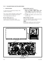
Page 225: ...e m Be careful not to touch the arm portion of the video head cleaner assembly to the peripheral tape guides When replacing the video head cleaner assem bly perform step 5 and later When replacing the cleaning roller perform step 3 and later 3 Replace the Cleaning Roller 1 Remove the CR spacer and remove the cleaning roller 2 Pass a new cleaning roller through the shaft as shown in the figure Then...

Page 226: ... head n Be careful not to touch the arm portion of the video head cleaner assembly to the peripheral tape guides 2 Align the two pins of the video head cleaner assembly to the two holes of the height determining plate 3 Tighten the screw while moving the video head cleaner assembly in the direction indicated by the arrow A counterclockwise 4 Fill in the hours of the cleaning roller re placement on...

Page 227: ...Position 1 Check that the cleaning roller does not come in contact with the upper drum and rotary heads of the inner drum as visual Specification 1 2 Check that the cleaning roller does not come in contact with the terminal on the full erase head as visual Specification 2 3 Press the iron core in the direction of the arrow At that time check that clearance exists between the ratchet bracket and th...

Page 228: ...r as shown in the figure 2 Connect the harness of the video head cleaner assembly to the connector CN231 white on the HN 268 board 3 Bind the two harnesses of the video head cleaner assembly and the full erase head with a new bundling band or equivalent Adjustment after Replacement 7 Confirm the Cleaning Solenoid Operation Refer to Section 3 3 4 F6 CLEAN PLG of the ALT SERVO CHECK menu Connect the...

Page 229: ...peration Refer to Section 3 3 4 F7 THREAD MOTOR of the SERVO CHECK menu Note Adjustment after the CL arm assembly replacement is not required However confirm the CL arm assembly operation Prepare a new stop washer when replacing the CL arm assembly Stop washer 2 3 3 669 596 00 Preparation 1 Turn the power off and disconnect the power cord 2 Remove the upper lid front assembly Refer to Section 1 3 ...

Page 230: ...he top of the CL arm assembly n Be careful not to touch the tools to the drum or peripheral tape guides when removing the stop washer 3 Remove the CL arm assembly from the threading ring n Do not remove the spring at the bottom of the CL arm assembly from the shaft Installation 2 Attaching the CL Arm Assembly 1 Pass a new CL arm assembly through the shaft while hooking the spring as shown in the f...

Page 231: ... gear of the gear box assembly manually and confirm the items below while repeating the threading and unthreading The CL arm assembly moves along the CL guide rail The cleaning roller cleans the CTL TC head and capstan motor shaft 4 Confirming the Threading Operation Refer to Section 3 3 4 F7 THREAD MOTOR of the SERVO CHECK menu Confirm the CL Arm Assembly Operation ...

Page 232: ... to Section 6 12 6 Adjusting the Drum Phase Refer to Section 7 2 3 7 Full Erasure Current Check Refer to Section 8 8 4 Note Head azimuth etc of the CTL FE head assembly are adjusted when shipping from the factory Never turn the screws in the CTL FE head assembly Except when adjustment Tools Cleaning cloth 3 184 527 01 Cleaning fluid 9 919 573 01 Torque screwdriver 6 kgf cm JB 5251 J 6252 510 A Tor...

Page 233: ...mbly 2 Confirm that the threading ring is in the unthreading end state 3 Put the slotted holes A and B of the CTL FE head assembly into the bosses of the chassis n Be careful not to touch the drum or peripheral tape guides 4 Place the boss of the chassis in the left side of the slotted hole A and tighten the screw 5 Connect the two harnesses to the connectors of CTL FE head assembly 3 Cleaning Cle...

Page 234: ... 6 Adjusting the Tape Running Refer to Sections 6 2 to 6 11 7 Electrical Adjustment after Replacing the AT Head Refer to Section 7 3 Note Never turn the screw in the AT head assembly Except when adjustment Tools Cleaning cloth 3 184 527 01 Cleaning fluid 9 919 573 01 Torque screwdriver 6 kg cm JB 5251 J 6252 510 A Torque screwdriver s bit 2 mm l 75 mm J 6323 420 A Preparation 1 Turn the power off ...

Page 235: ... Remove the two screws 3 Remove the AT head assembly from the MD base assembly n Be careful not to touch the drum or peripheral tape guides Installation 3 Attaching the AT Head Assembly 1 Remove the protection tape from the new AT head assembly 2 Align the two slotted holes of the AT head assembly with the two bosses of the chassis m Be careful not to touch the drum or periph eral tape guides Be c...

Page 236: ...um 3 Match and attach the positioning pin of the CL guide rail to the positioning hole of the MD base assembly 4 Tighten the two screws 5 Cleaning Clean the AT head surfaces with a cleaning cloth moistened with cleaning fluid n After cleaning wipe with a dry cleaning cloth Adjustment after Replacement 6 Adjusting the Tape Running Refer to Sections 6 2 to 6 11 7 Electrical Adjustment after Replacin...

Page 237: ... the Tape Running at Drum Exit Side Refer to Section 6 12 2 Notes Prepare the new stop washers when replacing the pinch arm assembly Stop washer 2 3 3 669 596 00 n When adjusting the vertical play the four stop washers at least are required for every replacement of the poly slider washer The poly slider washer for adjusting the vertical play may be required Poly slider washer t 0 13 mm 3 701 439 0...

Page 238: ...inch arm assembly from the threading ring n Do not remove the poly slider washer 2 t 0 25 mm and spring at the bottom of the pinch arm assembly from the shaft Installation 2 Attaching the Pinch Arm Assembly 1 Pass a new pinch arm assembly through the shaft while hooking the spring as shown in the figure m Insert the short end of the spring into the groove of the threading ring and hook the long en...

Page 239: ... to 4 below 2 Remove the stop washer n Be careful not to touch the tools to the peripheral tape guides when removing the stop washer 3 Confirm that the poly slider washer 2 is under the pinch arm assembly 4 Replace the poly slider washer 1 in the following order and meet the specification in step 1 1 Poly slider washer t 0 25 mm 2 Poly slider washer t 0 13 mm 3 No poly slider washer n Be sure to p...

Page 240: ...f the gearbox assembly by manual to set to the threading end state 2 Press the iron core of the pinch solenoid in the pull in direction and confirm that the clearance between the press arm A and B is met the specification 6 Confirming the Pinch Roller Solenoid Operation Refer to Section 3 3 4 F3 PINCH PLG of the ALT SERVO CHECK menu 7 Adjusting the Tape Running at Drum Exit Side Refer to Section 6...

Page 241: ...r Solenoid Operation Refer to Section 3 3 4 F3 PINCH PLG of the ALT SERVO CHECK menu 7 Adjusting the Tape Running at Drum Exit Side Refer to Section 6 12 2 Note The solenoid position etc of the pinch press assembly is already adjusted at the factory Never turn the screws other than the mounting screws when removing attaching Preparation 1 Turn the power off and disconnect the power cord 2 Remove t...

Page 242: ...ss assembly from the MD base assembly Installation 3 Attaching the Pinch Press Assembly 1 Align the sloted hole of the pinch press assembly with the pin of the MD base assembly 2 Fix the pinch press assembly with one screw Tightening torque 78 4 x 10_2 N m 8 0 kgf cm 4 Reconnecting the Harnesses 1 Reconnect the harnesses to the four connec tors CN216 CN231 and CN233 on the HN 268 board 2 Fix the h...

Page 243: ...ear of the gearbox assembly by manual to set to the threading end state 2 Press the iron core of the pinch solenoid in the pull in direction and confirm that the clearance between the press arm A and B is met the specification Adjustment after Replacement 6 Confirming the Pinch Roller Solenoid Operation Refer to Section 3 3 4 F3 PINCH PLG of the ALT SERVO CHECK menu 7 Adjusting the Tape Running at...

Page 244: ...the Capstan Motor Operation Refer to Section 3 3 4 F9 CAPSTN MOTOR of the SERVO CHECK menu 10 Performing the Servo Adjustment Refer to Section 3 4 2 F2 AUTO ADJ of the SERVO ADJUST menu 11 Adjusting the Tape Running at Drum Exit Side Refer to Section 6 12 2 Note Replace the capstan motor with the side panel of the unit down Tools Cleaning cloth 3 184 527 01 Cleaning fluid 9 919 573 01 Tape guide a...

Page 245: ...g the DR 508 Board 1 Place the unit with its one side down to remove the bottom plate Refer to Section 1 3 2 2 Disconnect the flexible board from each connector on the reel motors n Setting the reel tables at the S cassette position will ease the operation Refer to Section 5 1 3 3 Fully loosen the three screws on the DR 508 board n These screws should not be removed neces sarily 4 Open the DR 508 ...

Page 246: ...to drop the capstan motor 3 Remove the capstan motor Installation 4 Attaching the Capstan Motor 1 Pass a new capstan motor through the hole of the MD base assembly positioning as shown in the figure n Be careful not to damage the capstan motor shaft when passing the capstan motor through the hole of the MD base assembly 2 Tighten the two screws while holding the capstan motor by hand Tightening to...

Page 247: ...ses 3 Close the DR 508 board m Match the positioning hole of the DR 508 board with the positioning boss Be sure not to be caught the harness at the hinge portion 4 Tighten the three screws on the DR 508 board 5 Reconnect the flexible boards in step 2 to each connector on the reel motors c The connecting direction of the flexible board is specified When disconnecting the flexible boards from both r...

Page 248: ...fter Replacement 8 Confirming the Pinch Press Clearance Refer to step 5 in Section 5 9 9 Confirming the Capstan Motor Operation Refer to Section 3 3 4 F9 CAPSTN MOTOR of the SERVO CHECK menu 10 Performing the Servo Adjustment Refer to Section 3 4 2 F2 AUTO ADJ of the SERVO ADJUST menu 11 Adjusting the Tape Running at Drum Exit Side Refer to Section 6 12 2 ...

Page 249: ...pe Running Refer to Section 6 12 Note How to replace the reel table assembly is the same on the supply and take up sides Tools L shaped wrench 1 5 mm 7 700 736 05 Cleaning cloth 3 184 527 01 Cleaning fluid 9 919 573 01 Preparation 1 Turn the power off and disconnect the power cord 2 Remove the upper lid front assembly Refer to Section 1 3 1 3 Remove the cassette compartment Refer to Section 1 5 ...

Page 250: ... Clean the perimeter of the reel table assembly with a cleaning cloth moistened with cleaning fluid 2 Confirm that the number of the poly slider washers inserted in the reel motor shaft is the same as in the removal n When the poly slider washer is lost insert the following number of poly slider washers into the reel motor shaft S reel Poly slider washer t 0 13 mm x1 Sony part No 3 701 441 01 Poly...

Page 251: ... front assembly Refer to Section 1 3 1 3 Remove the cassette compartment Refer to Section 1 5 Removal 1 Removing the Brake Assembly 1 Unhook the spring put on the reel motor assembly 2 Release the claw by pressing in the arrow direction then remove the brake assembly Installation 2 Attaching the Brake Assembly 1 Pass a new brake assembly through the shaft of the reel motor assembly and fix it with...

Page 252: ...enu 14 Adjusting the Tape Running at Drum Entrance Side Refer to Section 6 12 1 Note In this unit it is not necessary to perform the traditional reel motor shaft slantness adjustment after the reel motor assembly replacement When replacing the reel motor be sure to perform the replacement as the reel motor assembly Never replace the single reel motor The parts making up the reel motor assembly is ...

Page 253: ... 2 Disconnect the flexible card wire from the connector CN1 on the SE 606A board 2 Removing the ME Wire T side only 1 Remove the ME wire from the wire holder 2 Remove the screw securing the lug terminal of the ME wire 3 Grasp the hole of the wire cover with a pair of pliers press the claw on the cover in the arrow direction and remove the wire cover from the plate holder T assembly 4 Remove the ME...

Page 254: ...side 3 Removing the Shaft Holder 1 Shift the reel motor assembly by turning the gear of reel shift motor 2 Align the guide portion of the reel motor assembly with the notch of the plate holder assembly n The reel motor assembly cannot be removed in the S or T cassette position 3 Remove the screw to remove the shaft holder Remove the Shaft Holder ...

Page 255: ... removal Installation 5 Reconnecting the Flexible Board 1 Clean the edge of the flexible board with a dry cloth 2 Connect the flexible board to a reel motor connector of a new reel motor assembly c The connecting direction of the flexible board is specified When disconnecting the flexible boards from both reel motor and DR 508 board be sure to connect them so that the character PWB on the flexible...

Page 256: ...on tighten it with one screw for each 9 Applying Grease on the Slide Shaft 1 Apply a very small portion of grease on the slide shaft and spread grease over the whole shaft n Use care not to put grease on other parts in vicinity 2 Confirm that the reel motor assembly moves smoothly when bringing to the S cassette position and L cassette position As for the method of shifting the reel motor assembly...

Page 257: ...w of the wire cover n Make sure the ME wire does not protrude out of the wall of the wire cover See the figure 3 Confirm that the ME wire moves smoothly and the reel table rotates when the tip of the ME wire is drawn Refer to 1 and 2 of step 5 in Section 5 21 4 Hang the tip of the ME wire on the wire holder and close the wire holder 11 Reattaching the SE 606A Board Reattach the SE 606A board in th...

Page 258: ...l Motor Assemblies Refer to steps 5 to 11 in Section 5 13 Adjustment after Replacement 5 Confirming the Reel Shift Motor Operation 6 Confirming the Tape Running at Drum Entrance Side Refer to Section 6 12 1 Preparation 1 Turn the power off and disconnect the power cord 2 Remove the upper lid front assembly Refer to Section 1 3 1 3 Remove the cassette compartment Refer to Section 1 5 Removal 1 Remo...

Page 259: ...serted in the slotted hole 3 Fix the motor holder assembly with two screws in the state of step 2 Tightening torque 78 4 x 10_2 N m 8 0 kgf cm 4 Connect the harness of the motor holder assembly to the connector CN2 of the MC sensor assembly and route the harness as shown in the figure n Arrange the too long harness with claws so that it will not contact with the driving section of the reel motor a...

Page 260: ...r to steps 5 to 11 in Section 5 13 Adjustment after Replacement 9 Confirming the Reel Shift Motor Operation 10 Confirming the Tape Running at Drum Entrance Side Refer to Section 6 12 1 Note When replacing the drive gear S assembly drive gear T assembly and the worm assembly prepare a new stop washer Stop washer 3 650 537 01 Preparation 1 Turn the power off and disconnect the power cord 2 Remove th...

Page 261: ...que 78 4 x 10_2 N m 8 0 kgf cm 6 Attaching the Drive Gear Assemblies 1 Pass the driving gear S and T assemblies on the shafts of the MD base assembly respectively 2 Re engage the marked portions gear of both driving gear S and T assemblies with the same groove of the worm gear 3 Fix the driving gear S and T assemblies with a new stop washer 7 Reattaching the Motor Holder Assembly Reattach the moto...

Page 262: ...acement in Section 5 19 TG 2 TG 2 assembly Refer to the Exploded views Refer to Sections 6 2 to 6 12 TG 3 TG 3 assembly Refer to the Exploded views TG 4 TG 4 assembly Refer to the Exploded views TG 5 Ring assembly Refer to Section 5 18 Refer to Adjustment after Replacement in Section 5 18 TG 6 Pinch arm assembly Refer to Section 5 8 Refer to Adjustment after Replacement in Section 5 8 TG 7 Ring as...

Page 263: ...aration 1 Turn the power off and disconnect the power cord 2 Remove the upper lid front assembly Refer to Section 1 3 1 3 Remove the cassette compartment Refer to Section 1 5 4 Open the AE 31H board Refer to figure in Section 5 1 2 Remove Attach the S Plate Assembly Removal 1 Removing the S Plate Assembly 1 Disconnect the all harnesses from the clamper of the S plate assembly 2 Disconnect the harn...

Page 264: ...y clockwise Tightening torque 78 4 x 10_2 N m 8 0 kgf cm c As the edge of tape cleaner is sharp use great care to avoid a hand cut 2 Connect the harness tape end sensor to the connector of the tape end sensor and fix it to the clamper 3 Fix the remaining harnesses disconnected in 2 of step 1 to the clamper Adjustment after Replacement 3 Adjusting the Tape Running at Drum Entrance Side Refer to Sec...

Page 265: ...ement 8 Confirming the Threading Motor Operation Refer to Section 3 3 4 F7 THREAD MOTOR of the SERVO CHECK menu Preparation 1 Turn the power off and disconnect the power cord 2 Remove the upper lid front assembly Refer to Section 1 3 1 3 Remove the cassette compartment Refer to Section 1 5 4 Open the AE 31H board Refer to the figure in Section 5 1 2 Removal 1 Removing the Video Head Cleaner Assemb...

Page 266: ...ing ring assembly then Insert the projection A of the gear box assembly in the positioning hole A of the MD base assembly 2 Press the gearbox assembly from above with fingers and confirm that the positioning bosses A and B are inserted into the positioning holes A and B of the MD base assembly The gear box assembly should make no rattles when pressed with fingers 3 Fix the gear box assembly with t...

Page 267: ...er to steps 5 and 6 in Section 5 17 18 Reattaching the Pinch Press Assembly Refer to steps 3 and 4 in Section 5 9 19 Putting the Unit into the Unthreading End Mode 20 Reattaching the S Tension Regulator Assembly Refer to step 2 in Section 5 19 21 Reattaching the S Plate Assembly Refer to step 2 in Section 5 16 1 22 Reattaching the T Drawer Assembly Refer to steps 3 to 6 in Section 5 21 23 Reattach...

Page 268: ...o Section 1 5 4 Open the AE 31H board Refer to figure in Section 5 1 2 Removal 1 Removing the Video Head Cleaner Assembly Remove the video head cleaner assembly Refer to steps 1 and 2 in Section 5 4 2 Disconnecting the Flexible Board Disconnect the flexible board from the connector CN220 on the DT 47 board 3 Disconnecting the Harnesses 1 Disconnect the harness from the connector of the AT head ass...

Page 269: ...to fall 6 Removing the Pinch Press Assembly Remove the pinch press assembly Refer to steps 1 and 2 in Section 5 9 7 Removing the S Plate Assembly Remove the S plate assembly Refer to step 1 in Section 5 16 1 8 Removing the S Tension Regulator Assembly Remove the S tension regulator Refer to step 1 in Section 5 19 9 Removing the T Drawer Assembly Remove the T drawer assembly Refer to steps 1 and 2 ...

Page 270: ...4 Attaching the Threading Ring Assembly Press the T tension arm in the arrow direction and install the threading ring assembly while attempting to fit it to the grooves of the ring rollers A and C 15 Attaching the Ring Roller B 1 Pass the ring roller B through the roller shaft while holding the threading ring assembly so that it does not come off from the grooves of the ring rollers A and C Then t...

Page 271: ...tion 5 16 1 22 Reattaching the T Drawer Assembly Reattach the T drawer assembly and confirm the T drawer assembly operation Refer to steps 3 to 6 in Section 5 21 23 Attaching the CL Guide Rail 1 Check if the deck is in the unthreading end state 2 Insert the portion A of the CL guide rail to the bottom of the drum 3 Match and attach the positioning pin of the CL guide rail to the positioning hole o...

Page 272: ...nnect the harness to the connector of the CTL head 28 Reattaching the Video Head Cleaner Assembly Reattach the video head cleaner assembly Refer to steps 4 to 6 in Section 5 4 Adjustment after Replacement 29 Confirming the Cleaning Solenoid Operation Refer to Section 3 3 4 F6 CLEAN PLG of the ALT SERVO CHECK menu 30 Performing the Tension Offset Adjustment Refer to Section 3 4 2 F4 TENSN OFFSET of...

Page 273: ... 6 Adjusting the Tape Running Refer to Sections 6 2 to 6 12 Note The S tension regulator assembly comprises of precision components and is adjusted strictly When removing installing use extreme care to turn only screws specified Tools Cleaning cloth 3 184 527 01 Cleaning fluid 9 919 573 01 Preparation 1 Set the unit into the unthreading end mode Refer to step 2 in Section 5 1 2 2 Turn the power of...

Page 274: ...embly 1 Clean the mounting surfaces between the S tension regulator assembly and the MD base assembly three contact surfaces 2 Connect the harness to the connector CN206 on the TR 119 board 3 Hook the harness on the A portion of the S tension regulator 4 Match the S tension regulator assembly with the positioning pin and the positioning hole of the MD base assembly then fasten with three screws so...

Page 275: ... 5000 5500 Adjustment after Replacement 5 Performing the Tension Offset Adjustment Refer to Section 3 4 2 F4 TENSN OFFSET of the ALT SERVO ADJUST menu 6 Adjusting the Tape Running Refer to Sections 6 2 to 6 12 ...

Page 276: ...rming the Tension Offset Adjustment Refer to Section 3 4 2 F4 TENSN OFFSET of the ALT SERVO ADJUST menu 12 Confirming the Tape Running at Drum Exit Side Refer to Section 6 12 2 Note The T tension regulator assembly comprises of precision components and is adjusted strictly When removing installing use extreme care to turn only screws specified Tools Cleaning cloth 3 184 527 01 Cleaning fluid 9 919...

Page 277: ...ion as shown in the figure n The shutter for detecting the threading unthreading end will be released from the T tension regulator assembly by turning the threading ring assembly 2 Disconnecting the Flexible Board Disconnect the flexible board from the connector CN220 on the DT 47 board 3 Removing the EQ Harness Retainer Remove the two screws fixing the EQ harness retainer and remove the EQ harnes...

Page 278: ... DT 47 board 2 Remove the DT 47 board and shift it to the arrow direction Secure the space to remove the T tension regulator assembly 5 Removing the T Tension Regulator Assembly 1 Unfasten the harness clamp then disconnect the harness from the connector CN207 on the TR 120 board 2 Remove the two screws and remove the T tension regulator assembly in the arrow direction Remove the T Tension Regulato...

Page 279: ... within the positioning hole of the M base assembly and fasten with two screws 4 Connect the harness to the connector CN207 on the TR 120 board 5 Fasten the harness connected to the TR 120 board together with the and harness connected to the DT 47 board with the harness clamp n Be careful that harnesses does not contact with the moving section of the regulator 7 Confirming the T Tension Regulator ...

Page 280: ...tainer Reattach the EQ harness retainer as shown in the figure then tighten it with the two screws 10 Reconnecting the Flexible Board Insert and lock the flexible board to the connector CN220 on the DT 47 board Adjustment after Replacement 11 Performing the Tension Offset Adjustment Refer to Section 3 4 2 F4 TENSN OFFSET of the ALT SERVO ADJUST menu 12 Confirming the Tape Running at Drum Exit Side...

Page 281: ...rming the Tape Running at TG 10 Guide Note The T Drawer Assembly is adjusted the roller height slant guide etc at shipping Never turn the mounting screws when removing attaching Tools L shaped wrench 1 5 mm 7 700 736 05 Cleaning cloth 3 184 527 01 Cleaning fluid 9 919 573 01 HDCAM SR cassette L cassette Preparation 1 Set the unit into the unthreading end mode Refer to step 2 in Section 5 1 2 2 Tur...

Page 282: ...the lug terminal of the ME wire 3 Grasp the hole of the wire cover with a pair of pliers press the claw on the cover in the arrow direction and remove the wire cover from the plate holder T assembly 4 Remove the ME wire from the T drawer assembly as shown in the figure 2 Removing the T Drawer Assembly 1 Disconnect the harness from the connector of the tape top sensor 2 Release the harness from the...
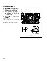
Page 283: ...er assembly and the MD base assembly 2 Insert the positioning boss B of the T drawer assembly into the positioning hole B at a shallow depth Fit the positioning boss A to the positioning hole A by pushing and turning from outside of the thread ring assembly 3 Fix the T drawer assembly with the two screws Tightening torque 78 4 x 10_2 N m 8 0 kgf cm 4 Connect the harness to the connector of the tap...

Page 284: ... claw of the wire cover n Make sure the ME wire does not protrude out of the wall of the wire cover See the figure 5 Confirming the ME Wire Operation 1 Confirm that the ME arm and T real table assembly are in mesh and the T side reel table rotates when lifting the loop of the tip of the ME wire upwardly Perform the check each at the L cassette position and S cassette position As for the method of ...

Page 285: ...e check that the lower surface of the roller does not come in contact with the surface B of the threading ring shaded portion in the figure 2 When threading check that the portion C of the threading ring pushes certainly the roller of the lock arm assembly and also check that the pin of the lock arm assembly pushes certainly the drawer guard 3 When the threading ring rotates toward the unthreading...

Page 286: ... If the specification is not satisfied confirm the T drawer attachment and the cassette that has been used for the tape running After confirmation again perform the step 7 If the specification cannot be satisfied perform the steps 8 and 9 8 Adjusting the Slant Guide Slantness Adjust the adjustment plate position by turning the adjustment hexagonal screw so that the specification is satisfied If th...

Page 287: ...ette Compartment Motor 10 Applying the Grease 11 Reconnecting the Harness CN935 CL 29 Board Adjustment after Replacement 12 Checking the Cassette Compartment Motor Operation Refer to Section 3 3 4 F8 CCM MOTOR of the SERVO CHECK menu Preparation 1 Turn off the power and disconnect the power cord 2 Remove the upper lid front assembly Refer to Section 1 3 1 3 Remove the cassette compartment Refer to...

Page 288: ...ion indicated by arrow A and take out the worm 3 Removing the Cassette Compartment Motor Spread the claw of the chassis and push out the cassette compartment motor from the inside of the cassette compartment 4 Removing the Motor Joint Loosen the set screw by two to three turns and remove the motor joint 5 Removing the Spacer and Disconnecting the Harness 1 Remove the spacer 2 Unsolder and disconne...

Page 289: ...ed in 2 of step 5 to a new motor n Solder a red wire to the side of marking of the motor 7 Attaching the Motor Joint 1 Pass the motor joint through the shaft of the motor and temporarily tighten the set screw 2 Confirm that the clearance between the motor joint and motor satisfies the specification when the motor joint is pushed toward the motor and tighten the set screw Tightening torque 60 x 10_...

Page 290: ...d portion of the motor with the marked portion of the chassis and fit the motor in the two claws while inserting the hole of the spacer into the boss of the chassis Simultaneously fit the hub of the worm in the two claws of the chassis 3 Confirm that the motor has been fixed 10 Applying the Grease Slightly apply the grease to the worm 11 Reconnecting the Harness Reconnect the harness of the casset...

Page 291: ...0 hours of energizing 1 Index 2 Notes Replace the fan motors when displaying a alarm informing for fan motor in addition to the periodic replacement When the fan motor stops because of trouble some components inside the unit may be heated to high temperatures Take care not to burn your hands by touching these components In service operation turn off the power and perform the service operation afte...

Page 292: ...urn the power off and disconnect the power cord 2 Remove the upper lid front assembly and upper lid rear assembly Refer to Section 1 3 1 Replacement 1 Removing the Cable Protector 1 Slide the cable protector in the arrow derec tion to remove 2 Remove the bead tie and open the edge holder 3 Remove the coaxial cables from the guide rail L 2 Removing the Plug in Boards Remove all the plug in boards R...

Page 293: ...gers down then lift up the bottom while pressing with a thumb 2 Remove the two claws of guide rail L from the bosses of the chassis 3 Remove the three hooks from the square holes of the chassis while lifting up the whole guide rail L 4 Remove the guide rail L in the arrow direction 4 Removing the Fan Motor 1 Disconnect the fan harness from the connec tor CN71 or CN72 on the MB 964 board 2 Remove t...

Page 294: ...to the bottom part of the guide rail L 3 Viewing from the side check if the three hooks of the guide rail L are fit in the square holes of the chassis 4 Push the guide rail L downward and fix it to the chassis with two claws 7 Reinstalling the Plug in Boards Reinstall the plug in board removed Refer to Section 1 12 n Reconnect the harnesses or coaxial cables correctly 8 Reattaching the Cable Prote...

Page 295: ... the Fan Motors 3 Attaching the Fan Motors 4 Connecting the Harnesses Preparation 1 Turn the power off then disconnect the power cord 2 Place the unit with the side facing down and remove the bottom plate Refer to Section 1 3 2 Replacement 1 Disconnecting the Harnesses 1 Disconnect the harnesses of the fan motors from the connectors CN73 and CN74 on the MB 964 board 2 Remove the harnesses of the f...

Page 296: ...otors Attach each new fan motor in the direction as shown in the figure then fix it with two screws Tightening torque 80 x 10_2 N m 8 0 kgf cm m Pay attention not to mistake the direction of the labeled side and the harness direction Be sure not to be caught the harnesses 4 Connecting the Harnesses 1 Connect the each harness of the fan motor to the connectors CN73 and CN74 on the MB 964 board Fan ...

Page 297: ...ent 1 Removing the Power Supply Unit 1 Remove the harness from the connector of the power supply unit 2 Remove the two screws securing the power supply unit 3 Lift up the power supply unit with holding the handle to disconnect the connector from CN100 on the MB 964 board 4 Remove the power supply unit from the chassis 2 Attaching the Power Unit 1 Put in a new power supply unit along the portion A ...

Page 298: ...irming the Search Dial Operation Refer to Section 3 3 3 F1 DIAL of the PANEL CHECK menu Preparation 1 Turn the power off and disconnect the power cord 2 Remove the control panel assembly Refer to Section 1 6 Removal 1 Removing the Rear Cover Remove the eight screws and remove the rear cover 2 Removing the Dial Assembly 1 Disconnect the harness from the dial assem bly 2 Remove the dial knob rubber ...

Page 299: ...e dial knob to the dial assembly with the screw Tightening torque 53 x 10_2 N m 5 5 kgf cm 4 Reattach the dial knob rubber to the dial knob 5 Connect the harness to the dial assembly 4 Reattaching the Rear Cover Reattach the rear cover to the key panel frame then fix it with eight screws Tightening torque 80 x 10_2 N m 8 0 kgf cm Adjustment after Replacement 5 Confirming the Search Dial Operation ...

Page 300: ...3 3 F5 LCD of the PANEL CHECK menu Note The LCD unit as the spare part includes the lamp unit Preparation 1 Turn the power off and disconnect the power cord 2 Remove the control panel assembly Refer to Section 1 6 Remove Attach the Key Panel Assembly Removal 1 Removing the Rear Cover Remove the rear cover Refer to step 1 in Section 5 25 2 Removing the Key Panel Assembly 1 Remove the MULTI CONTROL ...
Page 301: ...from the LCD unit Installation 4 Attaching the LCD Unit 1 Reattach the LCD shield case to a new LCD unit 2 Connect the CN 2511 board to the connector CN1 on the LCD unit 3 Connect the harnesses of the LCD unit to the connectors CN2 CN3 on the inverter unit 4 Reattach the LCD unit spacers and LCD cover assembly to the key panel frame then fix it with four screws Refer to the figure in step 2 Tighte...
Page 302: ... 5000 5500 6 Reattaching the Rear Cover Reattach the rear cover Refer to step 4 in Section 5 25 Adjustment after Replacement 7 Color Display Indication Test Refer to Section 3 3 3 F5 LCD of the PANEL CHECK menu ...

Page 303: ...step 4 in Section 5 25 Adjustment after Replacement 9 Color Display Indication Test Refer to Section 3 3 3 F5 LCD of the PANEL CHECK menu Note The two lamp units are located on the top and bottom at the back side of the LCD unit It is recommended to replace both lamp units at the same time Preparation 1 Turn the power off and disconnect the power cord 2 Remove the control panel assembly Refer to S...

Page 304: ...crews 6 Reattaching the LCD Unit Reattach the LCD unit Refer to step 4 in Section 5 26 1 7 Reattaching the Key Panel Assembly Reattach the key panel assembly Refer to step 5 in Section 5 26 1 8 Reattaching the Rear Cover Reattach the rear cover Refer to step 4 in Section 5 25 Adjustment after Replacement 9 Color Display Indication Test Refer to Section 3 3 3 F5 LCD of the PANEL CHECK menu PTP2 x 4...

Page 305: ... Test Refer to Section 3 3 3 F6 OEL of the PANEL CHECK menu Preparation 1 Turn the power off and disconnect the power cord 2 Remove the control panel assembly Refer to Section 1 6 Remove the Organic EL Indicator Module Removal 1 Removing the Rear Cover Remove the rear cover Refer to step 1 in Section 5 25 2 Removing the Key Panel Assembly Remove the key panel assembly Refer to step 2 in Section 5 ...

Page 306: ...claws of the organic EL indicator module 2 Connect the flexible card wire to the connec tor CN1 on the organic EL indicator module n When replacing the flexible card wire form the wire as shoun in the figure by hands 3 Attach the organic EL indicator module to the key panel frame then fix it with two screws Tightening torque 50 x 10_2 N m 5 0 kgf cm 5 Reattaching the Key Panel Assembly Reattach th...

Page 307: ...e the control panel assembly Refer to Section 1 6 Removal 1 Removing the CP 382 Board Perform the steps 3 to 7 in Section 5 30 6 to remove the CP 382 board 2 Removing the Inverter Unit 1 Disconnect the harness from the connector CN1 on the inverter unit 2 Remove the two nylon rivets and remove the inverter unit and unsulating sheet Installation 3 Attaching the Inverter Unit 1 Fix a new inverter un...

Page 308: ...5 102 SRW 5000 5500 Adjustment after Replacement 5 Color Display Indication Test Refer to Section 3 3 3 F5 LCD of the PANEL CHECK menu ...

Page 309: ... control panel Refer to Section 1 6 3 Secure the lower control panel to the 90 d position Refer to Section 1 6 Remove Attach the PC Card Adaptor Removal 1 Removing the PC Card Adaptor Press the card slot eject button of the system setup panel and eject the PC card adaptor Installation 2 Attaching the PC Card Adaptor Insert a new PC card adaptor to the card slot of the system setup panel PC card ad...

Page 310: ...four hooks and then remove the AE cover from the AE 31H board 5 Disconnect the four harnesses from the connectors CN100 CN200 CN600 and CN800 n When handling the harnesses connected to the AT head assembly CN100 CN200 and CN600 be sure not to apply the force to the AT head assembly If the force is applied perform the confirmation of the tape running at drum exit side Refer to Section 6 12 2 6 Remo...

Page 311: ... CN931 on the CL 29 board 4 Remove the two screws to remove the CL 29 board from the cassette compartment assembly and then open the arrow direction 5 Disconnect the flexible board from the connector CN933 on the CL 29 board 6 Disconnect the harness from the connector CN935 on the CL 29 board 7 Perform the installation in the reverse order from steps 2 to 6 Steps after Replacement 8 Confirm that t...

Page 312: ...onnector panel assembly Refer to Section 1 4 3 Remove all the screws fixing the XLR connectors 12 pcs 4 Remove the CP 376 CP 376A board by disconnect the connector from the CP 377 board 5 Perform the installation in the reverse order from steps 2 to 4 n The screws fixing the XLR connectors are two kinds Use the longer screws BVTT3 x 10 for fixing the double type connector Steps after Replacement 6...

Page 313: ... PSW3 x 8 fixing the lug terminal to the CP 378 board 5 Remove the two screws BVTT3 x 6 6 Remove the eight screws BVTP3 x 10 fixing the BNC connectors and remove the CP 377 board n Be careful not to loose the SW ornamental plates and the ornamental plate spacers at this time 7 Perform the removal in the reverse order from steps 2 to 5 n Fix the rug terminal of the ground harness to the CP 378 boar...

Page 314: ... Remove the four screws BVTT3 x 6 and eight screws for connectors to remove the CP 378 board n It is not required to remove the fixing screws for the REMOTE 2 PARALLEL I O connector 5 Perform the attachment in the reverse order from steps 2 to 4 m Be careful not to mistake the fixing screws for RS232C since these only are different from other connector fixing screws Fix the rug terminal of the gro...

Page 315: ... flexible card wires from the connectors CN502 and CN700 on the CP 382 board 7 Disconnect the harnesses from the connectors CN2 and CN3 on the inverter unit 8 Disconnect the harness from the connector CN300 on the CP 382 board 9 Remove the two nylon rivets and remove the inverter unit and insulating sheet Installation 10 Reattach the inverter unit to a new CP 382 board then fix it with the two nyl...

Page 316: ... fix it with the five screws Tightening torque 80 x 10_2 N m 8 0 kgf cm m Be sure not to be caught the harnesses shown in the figure between the key panel frame and CP 382 board Connect the connector CN503 on the CP 382 board to the CN1 on the KY 527 board surely 15 Connect the harness disconnected in step 4 to the connector CN601 on the CP 382 board 16 Reattach the rear cover Refer to step 4 in S...

Page 317: ...cord 2 Remove the upper lid front assembly Refer to Section 1 3 1 3 Remove one screw and remove the CUE 13 board in the arrow direction 4 Perform the installation in the reverse order from steps 2 and 3 Steps after Replacement 5 Perform the CUE playback system adjust ment Refer to Section 8 5 4 Remove the CUE 13 Board ...

Page 318: ...r to Section 5 24 5 Disconnect the flexble card wire from the connector CN1 on the DIO 69 board 6 Disconnect the connection between the HP 110 and FP 131 boards then remove the DIO 69 board in the arrow direction n For recorder only be careful when removing or installing the DIO 69 board support the portion A of the HP 110 board with fingers so that excessive force is not applied to the HP 110 boa...

Page 319: ...tting the reel tables at the S cassette position will ease the operation Refer to Section 5 1 4 5 Fully loosen the three screws on the DR 508 board 6 Open the DR 508 board in the arrow direc tion n Open the board slowly so that excessive force is not applied to the connected harness 7 Disconnect all the harnesses and flexible boards connected from the connectors CN65 200 to 208 210 212 to 216 on t...

Page 320: ...the harnesses between the bracket A and the MD base assembly 12 Connect all the harnesses and flexible boards that have been disconnected in step 7 13 Arrange the harnesses and fasten with wire clamps as shown in the figure n Arrange the harnesses correctly 14 Turn the gear of the reel shift motor to move the reel table at the middle position between the S and L cassette positions Refer to Section...

Page 321: ...connecting the flexible boards from both reel motor and DR 508 board be sure to connect them so that the character PWB on the flexible boards are shown at the connector sides of the DR 508 board Fig 1 If connected opposite side the DR 508 board will fail 17 Connect the flat cables that have been removed in step 3 to the connectors CN61 and CN62 on the MB 964 board 18 Arrange the power supply harne...

Page 322: ... DR 508 board Refer to steps 4 to 6 in Section 5 30 9 4 Disconnect the harness from the connector CN215 on the DR 508 board Refer to step 7 in Section 5 30 9 5 Disconnect the harness and the flexible board from the connectors CN200 and CN201 on the DT 47 board 6 Remove the ME wire and harness from the wire holder 7 Remove the three screws and remove the EQ harness retainer and DT 47 board 8 Perfor...

Page 323: ...ect the DIO 69 board Refer to Section 5 30 8 5 Open the lower control panel Refer to Section 1 6 6 Disconnect the connecting cable of the control panel 7 Remove the two screws fixing the FP fixed plate assembly 8 Disconnect the connector on the MB 964 board to pull out the FP fixed plate assembly from the chassis 9 Remove the two screws A to remove the FP 132 board 10 Remove the four screws B to r...

Page 324: ...panel and front panel Refer to Section 1 3 3 4 Remove the DIO 69 board Refer to Section 5 30 8 5 Remove the one screw to remove the top plate support 6 Disconnect the harnesses from the connectors CN2 and CN4 on the HP 110 board 7 Remove the volume knob and the nuts for fixing the headphone volume and headphone jack 8 Remove the three screws and remove the HP 110 board 9 Perform the installation i...

Page 325: ...fer to Section 5 26 1 5 Remove the eight screws and remove the insulator KY and KY 526 board from the key panel sub assembly 6 Perform the installation in the reverse order from steps 1 to 5 n Tighten the eight screws removed in step 5 as following torque Tightening torque 46 x 10_2 N m 4 5 kgf cm Steps after Replacement 7 Check the key operation Refer to Section 3 3 3 F7 KEY of the PANEL CHECK me...

Page 326: ... 5 30 6 4 Remove the seven screws and remove the KY 527 board from the key panel frame in the arrow direction 5 Perform the installation in the reverse order from steps 1 to 4 n Tighten the seven screws removed in step 4 as following torque Tightening torque 80 x 10_2 N m 8 0 kgf cm Steps after Replacement 6 Check the key operation Refer to Section 3 3 3 F7 KEY of the PANEL CHECK menu Key panel fr...

Page 327: ...der from steps 2 to 4 Steps after Replacement 6 Confirm that the corresponding format lamp indicator will light up when the cassette tape recorded in each format is inserted 5 30 16 SWC 43 Board Replacement 1 Turn the power off and disconnect the power cord 2 Remove the front panel assembly Refer to Section 1 3 3 3 Disconnect the harness from the connector CN1 on the LED 386 board 4 Remove the two...

Page 328: ...d harnesses from the connectors CN61 CN62 CN65 CN73 and CN74 on the MB 964 Board 4 Reattach the bottom plate temporarily 5 Restore the unit to the original position 6 Remove the upper lid front assembly and upper lid rear assembly Refer to Section 1 3 1 7 Remove the power supply unit Refer to step 1 in section 5 24 8 Remove all the plug in boards Refer to Section 1 12 9 Remove the connector panel ...

Page 329: ...ghtly lift up the MB 964 board at two A parts simultaneously while removing the board from the positioning pins slowly pull out the board until the connector connected to the FP 131 board is disconnected 15 Pull out the MB 964 board while paying attention not to touch the board rear side with the chassis 16 Perform the installation in the reverse order from steps 2 to 15 Steps after Replacement 17...

Page 330: ...00 and CN300 on the TC 104 board n When handling the harness connected to the AT head assembly CN100 be sure not to apply the force to the AT head assembly If the force is applied perform the confirmation of the tape running at drum exit side Refer to Section 6 12 2 6 Remove the two screws fixing the TC 104 board 7 Remove the TC 104 board from the MD base assembly 8 Perform the installation in the...

Page 331: ...ent 6 1 1 Tape Path Adjustment Flow Chart 6 1 2 Precautions Perform the tape path adjustment in the 59 94 Hz mode Each tape path adjustment is not necessary except for the 59 94 Hz mode However when the unit is usually used in each mode except for the 59 94 Hz mode it is recommended to perform the tape path check in the mode The mechanism of the tape path system is composed of precision parts and ...

Page 332: ... of each part of the tape path system It is illustrated in the threading end mode of the recorder TG in the figure means the tape guide 6 1 4 Cassette Compartment 1 The tape path adjustment should be performed under the state that the cassette compartment is removed If not some checks and adjustments may be impossi ble 2 When the tape path adjustment is performed with the cassette compartment remo...

Page 333: ...eight on the cassette so that it does not rise up The weight about 1 kg is suitable n Never attempt to disassemble the cassette tape 6 1 6 Tracking Control The Bit 1 of the DIP switch S802 on the SS 95 board enables the RV1001 variable resistor on the SS 95 board to control manually the tracking in the playback mode Bit 1 of S101 SS 95 ON upper side Enables tracking control manually RV1001 SS 95 O...

Page 334: ...e and lead surface Section 4 2 5 Stationary heads Section 4 2 6 Tape running system and tape cleaner Section 4 2 7 6 1 8 Alignment Tapes Alignment tapes for adjusting the tape path of each model are listed on the table below For the recording descriptions of each alignment tape refer to Section 1 20 HR2 1A Part No 8 960 076 11 HR2 1B Part No 8 960 076 41 HR5 1A Part No 8 960 076 01 HR5 1B Part No ...

Page 335: ...LAY mode should be made flat from the entrance to the exit However it may not be completely flat in some cases For such cases there should be no problems only that the specifications are satisfied Perform adjustments only when without the specifications System Setting 1 Set the System 1 Turn on the power and display the SYSTEM menu HOME menu SFT DIAG SFT F8 F9 SYSTEM menu For the SYSTEM menu refer...

Page 336: ...Alignment Tape 1 Press the switch S1002 on the SS 95 board during power on to set the reel tables to the S cassette position Refer to Section 5 1 3 2 Turn off the power 3 Set the alignment tape HR2 1B and put a weight about 1 kg onto it 3 Connect the Oscilloscope Connect the oscilloscope as follows CH 1 TP52 EQ 94 board CNF CG ENV signal CH 2 TP5 EQ 94 board SWP5 signal TRIG Set CH 2 as TRIG input...

Page 337: ...ck the alignment tape HR2 1B 00 00 to 20 00 in the PLAY mode m The RF envelope waveform is recorded on HR2 1B 00 00 to 20 00 only for C ch If extremely abnormal RF envelope waveform is output after replacing the drum assembly remove and reattach the drum assembly Refer to Section 5 2 NG examples of RF envelope waveform 2 Set Bit 1 of the DIP switch S802 on the SS 95 board to ON upper side to enabl...

Page 338: ...t side is NG Example NG NG NG NG 5 Check in the REV x x x x x 1 Mode 1 Set Bit 1 of the DIP switch S802 on the SS 95 board to OFF lower side to fix the tracking control 2 Play back the alignment tape HR2 1B 00 00 to 20 00 3 Set the REV x 1 mode and check that the RF envelope waveform satisfies specification 3 If the waveform at the entrance is without the specification 3 adjust tracking at the dru...

Page 339: ...h maintaining the state of the specification 4 When the specification 4 is not satisfied adjust the tracking at tape exit Refer to Section 6 4 The tape curl of the upper flange of TG 3 and lower flange of TG 4 are less than 1 10 of the tape width Spec 4 Flange Tape Tape curl volume TG 4 TG 3 TG 5 ...

Page 340: ...satisfies specification 6 5 Set the F FWD mode and check that the RF envelope waveform of the CH 2 satisfies specification 6 6 Set the REW mode and check that the RF envelope waveform of the CH 2 satisfies specification 6 If specification 6 is not satisfied connect the oscilloscope as follows and perform the adjustment in the Section 6 3 Tape Entrance Side or Section 6 4 Tape Exit Side CH 1 TP52 E...

Page 341: ...nt tape HR5 1B and put a weight about 1 kg onto it 3 Play back the HR5 1B in the PLAY mode 4 Set Bit 1 and Bit 3 of the DIP switch S802 on the SS 95 board to ON upper side Bit 1 ON The tracking control is enabled Bit 3 ON The DT operation is stopped 5 Rotate the tracking VR RV1001 SS 95 board clockwise to maximize the RF envelope waveform A1 of the CH 1 at the low level of the SWP1 signal CH 1 TP6...

Page 342: ...t the oscilloscope as follows CH 1 TP44 EQ 94 board CNF AE ENV signal CH 2 TP40 EQ 94 board CNF BF ENV signal TRIG TP5 EQ 94 board SWP5 signal Oscilloscope setting CH 1 500 mV DIV CH 2 500 mV DIV TRIG 5 V DIV TIME 5 ms 2 Set the recording tape BCT 40SR and put a weight about 1 kg onto it 3 Turn on the power 4 While pressing the PLAY button press the REC button to set the recording mode 5 Check tha...

Page 343: ...tion 6 2 first n In the video tracking adjustment the RF envelope waveform should be made flat to the entrance and exit However it may not be completely flat in some cases For such cases there should be no problems only that the specifications are satisfied Perform adjustments paying attention to the followings Perform only the adjustment indicated Do not rotate screws other than those specified i...

Page 344: ...he alignment tape HR2 1B 00 00 to 20 00 in the PLAY mode 3 Rotate the tracking VR RV1001 SS 95 board clockwise to set the center of the RF envelope waveform to 80 of the maximum output level 4 Loosen the height adjustment nut of TG 2 rotate it counterclockwise so that the tape does not in contact the upper flange Fig 1 5 Rotate the height adjustment nut of TG 1 to make the RF envelope waveform as ...

Page 345: ...loscope 2 Adjust the HDCAM DT Head Contact 1 Turn off the power then remove the HR2 1B 2 Set the alignment tape HR2 1A and put a weight about 1 kg onto it 3 Set Bit 1 and Bit 3 of the DIP switch S802 on the SS 95 board to ON upper side Bit 1 ON The tracking control is enabled Bit 3 ON The DT operation is stopped 4 Turn on the power then playback the HR2 1A in the PLAY mode 5 Rotate the tracking VR...

Page 346: ...HR2 1B and put a weight about 1 kg onto it 12 Turn on the power then play back the HR2 1B 00 00 to 20 00 in the PLAY mode 13 Rotate the tracking VR RV1001 SS 95 board clockwise to set the center of the RF envelope waveform to 80 of the maximum output level then check that the waveform satisfies the specification 11 14 Slightly rotate the height adjustment nut of TG 2 a little clockwise 15 Check ag...

Page 347: ...ion 6 2 n After adjusting be sure to reset Bit 1 and Bit 3 of the DIP switch S802 on the SS 95 board to OFF lower side Tape running Check at the Tape Entrance Side a TG 1 S tension regulator The tape runs in contact with the upper flange The tape curl is less than 1 10 of the tape width b TG 2 Entrance guide The tape runs in contact with the upper flange The tape curl is less than 1 10 of the tape...

Page 348: ... only that the specifications are satisfied Perform adjustments paying attention to the following Perform only the adjustment indicated Do not rotate screws other than those specified in the adjustments Take note that performing adjustments other than those required for making the RF envelope waveform flat may result in damages such as abnormal wear of mechanism parts and accompa nying deteriorati...

Page 349: ...nterclockwise by one to two turns so that the tape does not in contact with the upper flange of TG 3 n Don t turn excessively the nut or the tape bottom edge does in contact with the lower flange of TG 3 5 Turn the height adjustment nut of TG 4 clockwise so that the tape does not in contact with the lower flange of TG 4 6 Check that the RF envelope waveform satisfies the specification 14 Fig 1 If ...

Page 350: ... the RF envelope wave form becomes flat Fig 2 Simultaneously ensure that the tape does not in contact with the lower flange of TG 4 If contact perform step 5 If the waveform does not become flat perform the steps 1 to 3 check and adjustment below 1 Clean the drum lead with a wooden stick Refer to Section 4 2 4 2 Press down the tape by wooden stick very lightly and check to see that the tape is run...

Page 351: ...d head to tape contact Refer to Section 6 9 AT head position Refer to Section 6 10 3 Attach the CL Guide Rail Turn off the power then attach the CL guide rail 4 Recheck the Video Tracking Perform the steps 4 through 10 in Section 6 2 again n After adjustment be sure to reset Bit 1 of the DIP switch S802 on the SS 95 board to OFF lower side Tracking Adjustment at the Tape Exit Side Lead of drum exi...

Page 352: ...ment tape HR2 1B and put a weight about 1 kg onto it 3 Turn on the power 2 Connect the Oscilloscope Connect the oscilloscope as follows CH 1 TP400 TC 104 board CTL PB signal TRIG TP200 SS 95 board SV REF signal Oscilloscope setting CH 1 0 5 V DIV TIME 5 ms DIV Preparation CH 1 TP400 TC 104 board CTL PB signal TRIG TP200 SS 95 board SV REF signal TC 104 board side A 4 3 2 1 A B Connection of the os...

Page 353: ...e If the level increases perform step 4 B Adjustment 4 Adjust the CTL Head Height A When the Level Increases by Pressing Down the Tape Turn the adjustment nut counterclockwise in the arrow A direction so that the output waveform is maximum B When the Level Increases by Pushing Up the Tape Turn the adjustment nut clockwise in the arrow B direction so that the output waveform is maximum CTL Head Hei...

Page 354: ...t the alignment tape HR2 1B and put a weight about 1 kg onto it 3 Turn on the power 2 Connect the Oscilloscope Connect the oscilloscope as follows CH 1 TP35 EQ 94 board REC CG ENV signal CH 2 TP11 EQ 94 board SWP11 signal TRIG TP200 SS 95 board SV REF signal Oscilloscope setting CH 1 200 to 300 mV DIV CH 2 5 V DIV TRIG 5 V DIV TIME 2 ms DIV CH 1 TP35 EQ 94 board REC CG ENV signal CH 2 TP11 EQ 94 b...

Page 355: ...ol Bit 1 OFF lower side Bit 2 ON upper side 6 Read the output level LF at the center of the RF envelope waveform 7 Check that the level LV read at step 4 and the level LF read at step 6 satisfy specifi cation 2 If they does not satisfy the specifications 1 and 2 perform step 4 and later CTL Head Position Check LV LF S802 1 SS 95 board ON Tracking control Enabled Alignment tape HR2 1B 00 00 to 20 0...

Page 356: ...ew of the CTL FE head assembly by 1 4 to 1 2 turn 2 Insert a 3 mm flatbladed screwdriver into the notch of the CTL FE head assembly 3 Adjust the CTL FE head assembly position so that the output level at the center portion is maximum and the marker appears in the RF envelope waveform at the high level of the SV REF signal and low level of the SWP11 signal Specification 3 n The RF envelope waveform ...

Page 357: ...justment Be sure to adjust or check these related portions according to After the Adjust ment in this section after adjusting the AT head height Tools Alignment tape HR2 1A 8 960 076 11 Oscilloscope Tektronix TDS3054B or equivalent Preparation 1 Set the Alignment Tape 1 Turn off the power 2 Set the alignment tape HR2 1A and put a weight about 1 kg onto it 3 Turn on the power 2 Connect the Oscillos...

Page 358: ...ack the 1 kHz 0 VU signal portion 00 00 to 15 00 on the HR2 1A in the PLAY mode 2 Slightly press down the portion A shown in the figure and check to see that the CUE level decreases If the level increases perform step 4 A of next page 3 On the contrary slightly push up the portion B of the tape and check to see that the CUE level decreases If the level increases perform the step 4 B AT Head Height...

Page 359: ...mum Arrow 2 in Fig 2 n To stabilize the AT head height after the adjustment set the maximum output level with the AT head moved upward with the height adjustment screw turned clockwise After the Adjustment 5 Adjust the AT Head Azimuth Refer to Section 6 8 6 Adjust the AT Head Head to tape Contact Refer to Section 6 9 7 Adjust the AT Head Position Refer to Section 6 10 8 Recheck the AT Head Height ...

Page 360: ... Be sure to adjust or check these related portions according to After the Adjust ment in this section after adjusting the AT head azimuth Tools Alignment tape HR2 1A 8 960 076 11 Oscilloscope Tektronix TDS3054B or equivalent Preparation Preparation 1 Set the Alignment Tape 1 Turn off the power 2 Set the alignment tape HR2 1A and put a weight about 1 kg onto it 3 Turn on the power 2 Connect the Osc...

Page 361: ...re with the tip of a screwdriver Then check that the output waveform level is maximum After the Adjustment 4 Adjust the AT Head Head to tape Contact Refer to Section 6 9 5 Adjust the AT Head Position Refer to Section 6 10 6 Check the AT Head Height Refer to Section 6 7 7 Apply the Locking Compound Refer to Section 6 1 9 AT Head Azimuth Adjustment CUE output waveform Alignment tape HR2 1A 15 00 to ...

Page 362: ... portions according to After the Adjust ment in this section after adjusting the AT head head to tape contact Tools Alignment tape HR2 1A 8 960 076 11 Oscilloscope Tektronix TDS3054B or equivalent Torque screwdriver 6 kgf cm JB 5251 J 6252 510 A Torque screwdriver s bit 2 mm l 75 mm J 6323 420 A Preparation Preparation 1 Set the Alignment Tape 1 Turn off the power 2 Set the HR2 1A and put a weight...

Page 363: ...ct 1 Play back the 12 kHz 0 VU signal portion 15 00 to 30 00 on the HR2 1A in the PLAY mode 2 Slightly push portions A and B of the tape shown in the figure to increase the tape s wrapping angle against the AT head 3 Check that the increased amount of output level satisfies the specification If the specification is not satisfied perform steps 4 and later AT Head Head to tape Contact Check ...

Page 364: ...utput level 4 Tighten the two securing screws loosened in step 1 Tightening torque 19 6 x 10_2 N m 2 kgf cm 5 Recheck the AT Head Head to tape Contact Perform to previous step 3 in this section again After the adjustment 6 Check the AT Head Position Refer to Section 6 10 7 Check the AT Head Height Refer to Section 6 7 8 Check the AT Head Azimuth Refer to Section 6 8 AT Head Head to tape Contact Ad...

Page 365: ...ion Tools Alignment tape HR2 1B 8 960 076 41 Oscilloscope Tektronix TDS3054B or equivalent Preparation 1 Set the Alignment Tape 1 Turn off the power 2 Set the alignment tape HR2 1B and put a weight about 1 kg onto it 3 Turn on the power 2 Connect the Oscilloscope Connect the oscilloscope as follows CH 1 TP400 TC 104 board CTL PB signal CH 2 TP102 TC104 board TC PB signal TRIG TP200 SS 95 board SV ...

Page 366: ...p be tween the rising edges of CTL s 65 35 pulse and TC PB s 65 35 waveform signals satisfies the specification If the specification is not satisfied perform steps 4 and later n The TC signal is in 0 15 ms advance of the CTL signal Adjustment 4 Remove the CL Guide Rail 1 Turn off the power 2 Fully loosen the two screws then remove the CL guide rail Alignment tape HR2 1B 00 00 to 20 00 CTL PULSE TC...

Page 367: ...d position adjustment differ When adjusting apply the specification in AT head position adjustment The TC signal is in 0 15 ms advance of the CTL signal 5 Tighten the two screws loosened in step 1 Tightening torque 98 x 10_2 N m 10 0 kgf cm 6 Recheck the AT Head Position Perform previous step 3 in this section again 7 Attach the CL Guide Rail 1 Turn off the power then remove the align ment tape 2 ...

Page 368: ...nment tape HR2 1A and put a weight about 1 kg onto it 3 Turn on the power 2 Connect the Oscilloscope Connect the oscilloscope as follows CH 1 TP300 AE 31H board CUE signal Oscilloscope setting CH 1 200 mV DIV TIME 5 ms DIV Check 3 Check the CUE Output Level 1 Play back the 1 kHz 0 VU signal portion 00 00 to 15 00 on the HR2 1A in the PLAY mode 2 Check the CUE output level A 3 Set the REV x 1 mode ...

Page 369: ... is not satisfied repeat steps 1 through 4 mentioned above 5 Check the Tape running at Tape Exit Side In the following modes check that the tape running condition satisfies specification 2 PLAY mode REV x 1 mode If specification 2 is not satisfied adjust the tape guides height at the tape exit side Refer to step 5 at the Tape Exit Side in Section 6 12 2 If the height of the tape guide is adjusted ...

Page 370: ...Flow Chart of Tape running Check at Tape Entrance Side END OK OK NG NG OK START 4 Recheck the Tape running at Tape Entrance Side 1 Set the S Cassette Tape 2 Tape Running Check at the Tape Entrance Side 2 Tape Running Check at the Tape Entrance Side Video Tracking Check Section 6 2 3 Adjust the TG 1 and TG 2 Height A B C D E F G H J K L M N P 1 2 SS 95 board side A S1002 a TG 1 S tension regulator ...

Page 371: ... guide adjustment driver and adjust the height of TG 1 and TG 2 so that the specification 1 previous page is satisfied n Do not rotate screws other than the height adjustment nut Otherwise this may result in abnormal tape running or tape tension 4 Recheck the Tape running at Tape Entrance Side Perform step 2 and the video tracking check Refer to Section 6 2 If the specifications 1 and 2 on the pre...

Page 372: ... Running Check at the Drum Exit Side S Cassette 5 Adjust the TG 3 Exit Guide and TG 4 Height 3 Set the L Cassette Tape 4 Tape Running Check at the Tape Exit Side L Cassette 7 Adjust the Slant Guide Slantness 8 Check the Tape running at the Tape Guide of Cassette T side Video Tracking Check Section 6 2 Check 1 Set the S Cassette Tape 1 While turning on the power press the switch S1002 on the SS 95 ...

Page 373: ...r and lower portions of the tape guide Spec 4 Play mode TG 10 Tape running Check at Drum Exit Side 3 Set the L Cassette Tape 1 Turn off the power then remove the S cassette 2 Turn on the power 3 Press the switch S1002 on the SS 95 board to set the reel tables to the L cassette position 4 Turn off the power 5 Set the L cassette and put a weight about 1 kg onto it 6 Turn on the power 4 Tape Running ...

Page 374: ... the specification 3 is not still satisfied perform the adjustment in step 5 again 7 Adjust the Slant Guide Slantness The T drawer assembly RP including the slant guide is adjusted precisely at shipment The slantness of the slant guide is also center adjusted If specification 4 previous page is not satisfied re check the followings before adjusting the slantness The L cassette used for checking is...

Page 375: ...e Guide of Cassette T side 1 Press the STOP button to set the unthreading end mode 2 In the PLAY mode check that the tape satisfies specification 4 previous page when running at the TG 10 guide If specification 4 is not satisfied repeat steps 7 and 8 above ...

Page 376: ......

Page 377: ...after finishing adjustment Settings of switches on panels circuit boards Use the setting check sheets Refer to the installation manual Settings of the setup menu Use a Memory Stick or memory card Refer to 1 26 Memory Stick or Memory Card 7 1 2 Outline of Electrical Alignment In Section 7 explains the electrical alignment after replacing the following parts Drum assembly Section 7 2 AT head Section...

Page 378: ...he unit had been described to Section 3 Before adjusting attach the upper lid front assembly When other than extending the plug in board also attach the upper lid rear assembly Tools The following equipment or equivalent and fixtures are required Cleaning tape BCT HD12CL Separately available Alignment tapes HR5 1A Part No 8 960 076 01 HR5 1B Part No 8 960 076 31 ZR5 1 Part No 8 960 073 01 Option H...

Page 379: ...Drum phase system DT SAT ADJUST menu Automatic adjustment adjustment F3 HDCAM DT Data saving DT SAT ADJUST menu F1 NVRAM CTL 7 2 6 SAT signal level adjustment DT SAT ADJUST menu Automatic adjustment F4 HDSR SAT 7 2 7 PB equalizer adjustment HDCAM SR RF ADJUST menu Automatic adjustment F4 EQULZR ADJ Data saving EQUALIZER ADJUST menu F1 NVRAM CTL HDCAM RF ADJUST menu Automatic adjustment F4 EQULZR A...

Page 380: ...etting referring to Section 7 1 3 3 Set the VTR s buttons and setup menu as follows Location Item Customer setting Setting at Remarks adjustment Upper control panel REMOTE 1 9P ____________ 8 OFF Light off 2 50P ____________ 8 OFF Light off 3 Ethernet ____________ 8 OFF Light off Setup menu ITEM 109 KEY INHIBIT ____________ 8 OFF HOME menu F2 REC INH ____________ 8 OFF Function menu F1 TIMER SEL _...

Page 381: ... times to exit the ALT SERVO ADJUST menu Display the ALT MAINTE NANCE Menu 8 Perform the next adjustment Section 7 2 4 7 2 4 HDCAM SR DT System Adjustment Alignment tape HR5 1B m Cue up the alignment tape to the time code 00 10 00 00 in advance When using the alignment tape not located to the time code 00 10 00 00 exit the maintenance mode and cue it up Then eject the alignment tape once When perf...

Page 382: ...this data save is completed normally 7 Exit the maintenance mode 7 2 6 HDCAM SR SAT Signal Level Adjustment m This adjustment is required in the 29 97 Hz 25 Hz and 23 976 Hz modes Because adjustment data is automatically saved in the NV RAM on the EQ 94 board when the automatic adjustment is completed saving the data is not required Alignment tape HR5 1B n Cue up the alignment tape to the time cod...

Page 383: ...each mode 7 Reset the system to the 29 97 Hz mode referring to Section 7 1 3 8 Exit the maintenance mode 7 2 8 HDCAM SR DT Measurement m This measurement is required in the 23 976 Hz 24 Hz 25 Hz 29 97 Hz and 30 Hz modes Because measurement data is automatically saved in the NV RAM on the EQ 94 board when the automatic measurement is completed saving the data is not required Alignment tape HR5 1B n...

Page 384: ...the NV RAM CONTROL menu 7 Select the SAVE ALL DATA by pressing the cursor keys then press the F10 EXIT key to saving data The message Save Complete will be displayed when this data save is completed normally 8 Eject the alignment tape 9 Perform the next adjustment 2 HDCAM Format 2 HDCAM Format Alignment tape HR5 1A 1 Press the F2 FMT SEL key several times to select the HDCAM 2 Insert the alignment...

Page 385: ...tment 1 HDCAM SR Format Tools Cleaning tape BCT HD12CL Separately available Recording tape BCT SR series Separately available n Use the blank tape erased using the tape eraser etc in advance or a new blank tape Preparation Clean with the cleaning tape Insert the cleaning tape BCT HD12CL The EJECT button blinks and the PLAY button light Then the cleaning tape is played back for about 10 seconds bef...

Page 386: ...enu For the RF ADJUST menu refer to Section 3 4 5 2 Press the F1 FMT SEL key several times to select the HDCAM 3 Press the F5 REC ADJ key to display the REC ADJUST menu 4 Insert the recording tape 5 To execute the automatic adjustment for the recording current press the F6 ALL CH ADJ key then press the SET key Message Complete will be displayed when this adjustment is completed normally Saving the...

Page 387: ... n The audio analyzer should be filtered through 80 kHz LPF throughout adjustment Frequency counter ADVANTEST R5362B Band pass filter 1 kHz Time code generator SONY BVG 1600 SONY BVG 1600PS Time code reader SONY BVG 1500 SONY BVG 1500PS Oscilloscope TEKTRONIX TDS3054B or equivalent Extension board EX 949 Part No A 8347 714 A Alignment tapes HR5 1A Part No 8 960 076 01 HR5 1B Part No 8 960 076 31 R...

Page 388: ...CUE 13 CUE OUT 4 CUE PB Frequency Response Adjustment 1RV203 AE 31H CUE OUT 5 TC Insert Cross talk Adjustment 1RV701 AE 31H CUE OUT 1RV703 AE 31H 7 3 5 CUE REC System Adjustment 1 CUE Input Level Adjustment 1RV100 CUE 13 CUE OUT 2 CUE REC VCA Adjustment 1RV101 CUE 13 CUE OUT 3 CUE REC VCA Distortion Ratio Adjustment 1RV103 CUE 13 CUE OUT 4 CUE Erace Current Adjustment 1LV600 AE 31H TP601 AE 31H 5 ...

Page 389: ...rning off the power reset the DIP switches of APR 62 board and CUE 13 board to the factory settings Board Ref No Address Item Customer setting Factory setting APR 62 S1200 F 3 Analog audio CH1 output level ______________ 8 4 dBm _20 dB all OFF output headroom S2200 F 3 Analog audio CH2 output level ______________ 8 4 dBm _20 dB all OFF output headroom CUE 13 S100 C 1 CUE input level ______________...

Page 390: ...ontrol panel REMOTE 1 9P ______________ 8 OFF Light off 2 50P ______________ 8 OFF Light off 3 Ethernet ______________ 8 OFF Light off Lower control panel PB LEVEL button CH1 ______________ 8 PRESET CH2 ______________ 8 PRESET CH8 ______________ 8 PRESET Setup menu ITEM 109 KEY INHIBIT ____________ 8 OFF HOME menu F2 REC INH ____________ 8 OFF TC menu F1 TIME SEL ____________ 8 TC F5 TCR SEL _____...

Page 391: ...ore 1 LTC Erasure Current Adjustment Measuring equipment Audio analyzer Recording tape BCT SR series n For this recording tape prepare a blank tape erased using the tape eraser etc in advence 1 Connect the audio analyzer V rms measurement mode to TP201 A 2 on the TC 104 board GND E100 TC 104 A 2 2 Insert the recording tape 3 Check the level on the audio level meter in the REC mode Adj point 1LV200...

Page 392: ...zer Use this measurement value as the reference level 0 dB 8 Check the PB level on the audio analyzer while playing back the no signal recorded portion in PLAY mode Specification _40 dB or less Regard a level of the audio signal recorded portion as 0 dB CH 1 A A CH 1 3 LTC OA Check Measuring equipment Oscilloscope Time code generator and reader Recording tape BCT SR series n For this recording tap...

Page 393: ... settings Check that any setting on the panel or the menu on the VTR is well prepared for processing adjustments Refer to 7 3 2 Common Preparation 6 Check the warming up Warming up of equipment to be used 20 minutes or more 1 CUE PB Level Adjustment 1 Short circuit TP101 CUE 13 D 1 and E100 CUE 13 C 1 with a shorting clip 2 Connect the audio level meter to TP102 CUE 13 B 2 GND E103 CUE 13 C 2 3 Pl...

Page 394: ...dio analyzer to CUE OUT connector of the connector panel 2 Set the audio analyzer as follows Measuring mode LEVEL dBu Input Filter 80 kHz LPF 3 Play back the portion of 1kHz 4 dBu of the align ment tape 4 Check audio level using the audio analyzer and then adjust it Adjusting point 1RV102 CUE 13 D 1 Specification 4 0 0 2 dBu 4 CUE PB Frequency Response adjustment 1 Connect the audio analyzer to CU...

Page 395: ...RV701 TP100 RV202 RV201 RV200 RV205 RV204 TP202 TP201 TP401 TP400 RV401 E600 TP601 RV400 TP300 RV300 TP200 TP500 E100 RV101 RV102 S100 LV400 LV600 T500 E500 S200 AE 31H Board Side A 7 3 5 CUE REC System Adjustment CUE 13 AE 31H Boards SRW 5500 only Tools Audio signal generator Tektronix SG5010 or equivalent Audio analyzer Audio Precision System One Two or equivalent Audio level meter Hewlett Packa...

Page 396: ... 0 1 dBu 3 CUE REC VCA Distortion Ratio Adjustment 1 Input 1 kHz 4 dBu audio signal to CUE INPUT connector of the connector panel 2 Connect the audio analyzer to CUE OUT connecter of the connector panel 3 Set the audio analyzer as follows Measuring mode THD N Range 2 Input Filter 80 kHz LPF 4 Check the distortion ratio using the audio analyzer and then adjust it Adjusting point 1RV103 CUE 13 C 1 S...

Page 397: ...st the level of 10 kHz until it equates with the level of 1 kHz Then check each of other frequen cy alike Adjusting point REC mode 1RV401 AE 31H C 5 Specification PB mode Each frequency level 1 kHz level 0 9 dB 5 CUE Bias Frequency Adjustment 1 Connect the frequency counter to TP500 AE 31H F 3 GND E500 AE 31H F 4 2 Insert the recording tape to have the VTR in the recording mode 3 Check the frequen...

Page 398: ......

Page 399: ...se the setting check sheets Refer to the installation manual Settings of the setup menu Use a Memory Stick or memory card Refer to 1 26 Memory Stick or Memory Card 8 1 2 Outline of Electrical Alignment In Section 8 explains the all electrical adjustment to each block Block Reference Contents Object of adjustment Power supply unit Section 8 2 Output voltage check of power supply unit Servo DT Secti...

Page 400: ...Section 3 3 9 2 Take notes of the customer settings for the following setting items 3 Change the following setting items to the settings for adjustment Setting item Customer setting F4 SYSTEM SIGNAL 4 2 2 YPbPr 4 4 4 RGB F1 SYSTEM LINE 1080 720 F2 SYSTEM SCAN Interlace PsF Progressive F3 SYSTEM FREQ 23 98 24 25 29 97 30 50 59 94 60 F7 ACTIVE LINE 1080 1035 ...

Page 401: ... Wait for 10 minutes after turning on the power Voltage Check Check each output voltage of power supply lines n It is no problem although checking voltage may exceed specified voltage when the options are not installed Output voltage Specification Test point 2 5 V 2 5 0 22 _0 15 V TP1 EX 873 3 4 V 3 4 0 25 V TP2 EX 873 6 2 V 6 2 0 3 V TP3 EX 873 15V 15 1 2 V TP4 EX 873 _6 2 V _6 2 0 6 V TP5 EX 873...

Page 402: ...nt must be performed in the 23 976 Hz 24 Hz 25 Hz 29 97 Hz and 30 Hz modes SAT signal adjustment is required in the 23 976 Hz 25 Hz and 29 97 Hz modes For detail of each menu in the maintenance mode refer to Section 3 The countermeasures against the malfunction of an automatic adjustment an error message ADJUST INCOMPLETE will be displayed on the color display of the unit had been described to Sec...

Page 403: ...tinuity automatic adjustment SERVO ADJUST menu F2 AUTO ADJ Data saving SERVO ADJUST menu F1 NVRAM CTL 8 3 5 HDCAM SR DT system adjustment DT SAT ADJUST menu HDCAM SR format playback F2 HDSR DT Data saving DT SAT ADJUST menu F1 NVRAM CTL 8 3 6 HDCAM DT system adjustment DT SAT ADJUST menu HDCAM format playback F3 HDCAM DT Data saving DT SAT ADJUST menu F1 NVRAM CTL 8 3 7 HDCAM SR SAT signal level a...

Page 404: ...he SERVO ADJUST menu 8 When the next adjustment Section 8 3 4 is not performed exit the maintenance mode 8 3 3 HDCAM RF Switching Position Adjustment SRW 5500 only Alignment tape HR2 1A n Rewind the alignment tape to the tape beginning in advance 1 Activate the ALT MAINTENANCE menu and display the ALT SERVO ADJUST menu HOME menu SFT DIAG SFT F8 ALT F4 ALT ALT SERVO AD JUST menu For the ALT SERVO A...

Page 405: ...nance mode 8 3 5 HDCAM SR DT System Adjustment Alignment tape HR5 1B m Cue up the alignment tape to the time code 00 10 00 00 in advance When using the alignment tape not located to the time code 00 10 00 00 exit the maintenance mode and cue it up Then eject the alignment tape once When performing this adjustment continuously from Section 8 3 4 start this adjustment from step 2 1 Activate the ALT ...

Page 406: ...steps 2 to 7 again for each mode 7 Reset the system to the customer setting referring to Section 8 1 3 8 Exit the maintenance mode 8 3 6 HDCAM DT System Adjustment Alignment tape HR5 1A m Cue up the alignment tape to the time code 00 10 00 00 in advance When using the alignment tape not located to the time code 00 10 00 00 exit the maintenance mode and cue it up Then eject the alignment tape once ...

Page 407: ...each mode 7 Reset the system to the customer setting referring to Section 8 1 3 8 Exit the maintenance mode 8 3 9 HDCAM SR DT Measurement m This measurement is required in the 23 976 Hz 24 Hz 25 Hz 29 97 Hz and 30 Hz modes Because measurement data is automatically saved in the NV RAM on the EQ 94 board when the automatic measurement is completed saving the data is not required Cue up the alignment...

Page 408: ...de and the 23 98 Hz mode Adjust in the 29 97 Hz mode and then adjust in the 25 Hz mode and the 23 98 Hz mode For detail of each menu in the maintenance mode refer to Section 3 Tools The following equipment or equivalent and fixtures are required Cleaning tape BCT HD12CL Separately available Alignment tapes HR5 1A Part No 8 960 076 01 HR5 1B Part No 8 960 076 31 ZR5 1 Part No 8 960 073 01 Option HK...

Page 409: ...HDCAM RF ADJUST menu F2 RF ALL ADJ Data saving RF ALL ADJUST menu F1 NVRAM CTL Digital BETACAM RF ADJUST menu Option HKSR 5002 installed model only F2 RF ALL ADJ Data saving RF ALL ADJUST menu F1 NVRAM CTL When wish to single out adjusting only for recording current of the VTR refer to Section 8 4 3 Record ing Current Adjustment Section Item Section title Adjustment point Remarks 8 4 3 Recording c...

Page 410: ...the VTR through the power for 20 minutes or more 4 Check the Operation Mode Check that the unit set into the 29 97 Hz mode If does not change the system setting referring to Section 8 1 3 Precautions on the automatic adjustment Be careful not to touch the search dial and buttons which have an effect on tape running during the automatic adjustment If tape running condition is changed optimum adjust...

Page 411: ...ng the cursor keys then press the F10 EXIT key to saving data The message Save Complete will be displayed when this data save is completed normally 10 Eject the recording tape 11 When the next adjustment 2 HDCAM Format is not performed exit the maitenance mode and perform the 4 Adjustment in the 25 Hz Mode 2 HDCAM Format n When performing this adjustment continuously from 1 HDCAM SR Format start t...

Page 412: ...refer to Section 3 4 5 2 Press the F1 FMT SEL key several times to select the DIGITAL BETACAM When performing this adjustment continuously from 2 HDCAM Format press the F2 FMT SEL key several times and perform step 4 and later 3 Press the F2 RF ALL ADJ key to display the RF ALL ADJUST menu 4 Insert the alignment tape then rewind it to the tape beginning 5 To execute the automatic adjustments press...

Page 413: ...ting the adjustment warm up the VTR through the power for 20 minutes or more 4 Check the Operation Mode Check that the unit set into the 29 97 Hz mode If does not change the system setting referring to Section 8 1 3 Recording Current Adjustment 1 HDCAM SR 1 Activate the ALT MAINTENANCE menu and display the RF ADJUST menu HOME menu SFT DIAG SFT F8 ALT F7 RF ADJUST menu For the RF ADJUST menu refer ...

Page 414: ...c adjustment for the recording current press the F6 ALL CH ADJ key then press the SET key Message Complete will be displayed when this adjustment is completed normally Saving the Data n Do not save the adjustment data if the automatic adjust ment was not completed properly 6 Press the F1 NVRAM CTL key to display the NV RAM CONTROL menu 7 Select the SAVE ALL DATA by pressing the cursor keys then pr...

Page 415: ...red for the audio system CUE system adjustments Audio analyzer AUDIO PRECISION System One SYS 22A Two SYS 2022A Digital Voltmeter ADVANTEST R6441B CUE system Oscilloscope TEKTRONIX TDS3054B CUE system Frequency Counter ADVANTEST R5362B CUE system Extension boards EX 873 Part No A 8346 141 A Audio system EX 949 Part No A 8347 714 A CUE system Shorting clip 1 pc CUE system Cleaning tape BCT HD12CL S...

Page 416: ...V104 CUE 13 CUE OUT CUE PB VCA Adjutment 1RV102 CUE 13 CUE OUT CUE PB Frequency Response Adjustment 1RV203 AE 31H CUE OUT TC Insert Cross talk Adjutment 1RV701 AE 31H CUE OUT 1RV703 AE 31H 8 5 5 CUE REC System Adjustment CUE 13 AE 31H boards CUE Input Level Adjustment 1RV100 CUE 13 CUE OUT CUE REC VCA Adjustment 1RV101 CUE 13 CUE OUT CUE REC VCA Distortion Ratio Adjutment 1RV103 CUE 13 CUE OUT CUE...

Page 417: ... OFF S3200 E 3 Analog audio CH3 output level output headroom ______________ 8 4 dBm _20 dB all OFF S4200 E 3 Analog audio CH4 output level output headroom ______________ 8 4 dBm _20 dB all OFF S1300 G 3 Monitor L output level output headroom ______________ 8 4 dBm _20 dB all OFF S2300 G 3 Monitor R output level output headroom ______________ 8 4 dBm _20 dB all OFF 2 Switche setting of the CUE 13 b...

Page 418: ...______ 8 PRESET CH6 ______________ 8 PRESET CH7 ______________ 8 PRESET CH8 ______________ 8 PRESET CH9 ______________ 8 PRESET CH10 ______________ 8 PRESET CH11 ______________ 8 PRESET CH12 ______________ 8 PRESET REC LEVEL button CH1 ______________ 8 PRESET CH2 ______________ 8 PRESET CH3 ______________ 8 PRESET CH4 ______________ 8 PRESET CH5 ______________ 8 PRESET CH6 ______________ 8 PRESET ...

Page 419: ...V4200 APR 62 E 3 Specification 3 95 0 1 dBm at 600 Z load 8 5 3 Analog Audio Output System Adjustment APR 62 Board Tools Audio analyzer AUDIO PRECISION System One Two or equiva lent Extension board EX 873 Preparation 1 Extend the APR 62 board with an extension board EX 873 After turning off the power extend the APR 62 board 2 Check the settings Refer to 8 5 2 Common Preparation 3 Check that the eq...

Page 420: ...lett Packard HP3400A or equivalent Digital voltmeter Advantest TR6845 or equivalent Extension board EX 949 Shorting clip Alignment tapes HR5 1A Preparation 1 Check the switch settings on the APR 62 CUE 13 boards Reset all the settings of these boards to the factory settings Refer to 1 Switches Settings in 8 5 2 Common Preparation 2 Extend the CUE 13 board with an extension board EX 949 n After tur...

Page 421: ...udio analyzer to CUE OUT connector of the connector panel 2 Set the audio analyzer as follows Measuring mode LEVEL dBu Input Filter 80 kHz LPF 3 Play back the portion of 1kHz 4 dBu of the align ment tape 4 Check audio level using the audio analyzer and then adjust it Adjusting point 1RV102 CUE 13 D 1 Specification 4 0 0 2 dBu 4 CUE PB Frequency Response adjustment 1 Connect the audio analyzer to C...

Page 422: ...3 RV702 RV700 RV703 RV701 TP100 RV202 RV201 RV200 RV205 RV204 TP202 TP201 TP401 TP400 RV401 E600 TP601 RV400 TP300 RV300 TP200 TP500 E100 RV101 RV102 S100 LV400 LV600 T500 E500 S200 8 5 5 CUE REC System Adjustment CUE 13 AE 31H Boards SRW 5500 only Tools Audio signal generator Tektronix SG5010 or equivalent Audio analyzer Audio Precision System One Two or equivalent Audio level meter Hewlett Packa...

Page 423: ...tment 1 Input 1 kHz 4 dBu audio signal to CUE INPUT connector of the connector panel 2 Connect the audio analyzer to CUE OUT connector of the connector panel 3 Set the audio analyzer as follows Measuring mode LEVEL dBu Input filter 80 kHz LPF 4 Check the level using the audio analyzer and then adjust it Adjusting point 1RV101 CUE 13 B 1 Specification 4 0 0 1 dBu 3 CUE REC VCA Distortion Ratio Adju...

Page 424: ...Hz 5 Play back the recorded portion and then check the level for each frequency using the audio analyzer If the level is not within the specification adjust it in the REC mode while checking the level in the PB mode Firstly adjust the level of 10 kHz until it equates with the level of 1 kHz Then check each of other frequen cy alike Adjusting point REC mode 1RV401 AE 31H C 5 Specification PB mode E...

Page 425: ...ard Only if the specification is not satisfied perform the adjustment Perform the Sections 8 6 3 and 8 6 4 in order Section Item Section title Adjustment point Test point Remarks 8 6 2 SD SDI free running frequency adjustment 1080 29 97 PsF or CH1 CH2 1RV1200 VPR 79 TP1200 VPR 79 1080 25 PsF CH3 1RV1201 VPR 79 TP1201 VPR 79 8 6 3 SD video output adjustment 525 59 94 Hz output 1080 59 94i COMPOSITE...

Page 426: ...ADVANTEST R5362B or equivalent Extension board EX 873 VPR 79 board suffix 11 only Preparation 1 Extend the VPR 79 board with an extension board EX 873 Board suffix 11 only After turning off the power extend the VPR 79 board 2 Connect the oscilloscope Connect the frequency counter to the CH 2 output of the oscilloscope and set the oscilloscope as follows CH 2 DC2 V DIV TIME 100 uS DIV 3 System sett...

Page 427: ...power to them for 30 minutes or more Composite Video Output Level Adjustment 1 Display the SD OUT ADJUST menu HOME menu SFT DIAG SFT F8 ALT F6 SD OUT ADJUST menu For the SD OUT ADJUST menu refer to Section 3 4 4 2 Press the F2 VIDEO LEVEL key several times for the setting to ON Composite Output Adjustment 3 Connect the 75 Z terminator to the SD OUT COM POSITE connector then connect the oscilloscop...

Page 428: ...ing to Section 8 1 3 Composite Video Output Level Adjustment 1 Display the SD OUT ADJUST menu HOME menu SFT DIAG SFT F8 ALT F6 SD OUT ADJUST menu For the SD OUT ADJUST menu refer to Section 3 4 4 2 Press the F2 VIDEO LEVEL key several times for the setting to ON Composite Output Adjustment 3 Connect the 75 Z terminator to the SD OUT COM POSITE connector then connect the oscilloscope 4 Check the wa...

Page 429: ...loscope TEKTRONIX TDS3054B Frequency counter ADVANTEST R5362B 75 Z terminator 1 pc Adjustments Section Item Section title Adjustment point Test point 8 7 2 INT 74 MHz frequency adjustment 29 97 Hz mode 1RV1700 HPR 8 HPR 8A TP1713 HPR 8 HPR 8A 30 Hz mode 1RV1701 HPR 8 HPR 8A TP1714 HPR 8 HPR 8A 8 7 3 HD REF output adjustment SYNC level 1RV1702 HPR 8 HPR 8A HD REF OUT 1 ...

Page 430: ...tment when the IC1703 IC1708 or X1702 on the HPR 8 HPR 8A board was replaced Tools Oscilloscope TEKTRONIX TDS3054B or equivalent Frequency counter ADVANTEST R5362B or equivalent Preparation 1 Check the setup menu setting ITEM 005 SERVO AV REFERENCE select input 2 Connect the oscilloscope Connect the frequency counter to the CH 2 output of the oscilloscope and set the oscilloscope as follows CH 2 D...

Page 431: ...C Level adjustment SYNC Level Adjustment 1 Connect the 75 Z terminator to the HD REF OUT 1 connector then connect the oscilloscope 2 Check the waveform of the oscilloscope then adjust the SYNC level A Adjusting point 11702 HPR 8 HPR 8A B 1 Specification A 300 5 mV A RV1702 A B C D E F G H J K 1 2 3 4 5 D2201 D2203 D2204 D2205 D2207 S200 S2000 S600 RV1600 RV1700 RV1701 TP100 TP101 TP1100 TP1600 TP1...

Page 432: ...setting referring to Section 8 1 3 Tools To perform the time code system alignment for the VTR prepare the following equipment or equivalent and fixtures Oscilloscope TEKTRONIX TDS3054B Audio analyzer AUDIO PRECISION System One SYS 22A Two SYS 2022A Alignment tape HR5 1B Part No 8 960 076 41 Recording tape SONY BCT SR series HDCAM SR cassette Separately available n Use the blank tape erased using ...

Page 433: ... the adjustments n Reset all the settings to the customer settings after completing the alignment Location Item Customer setting Setting at adjustment Remarks Switch panel KEY INHIBIT switch ____________ 8 OFF Upper control panel REMOTE 1 9P ____________ 8 OFF Light off 2 50P ____________ 8 OFF Light off 3 Ethernet ____________ 8 OFF Light off Setup menu ITEM 109 KEY INHIBIT ____________ 8 OFF HOM...

Page 434: ...B 3 During play back the alignment tape in the PLAY mode check the level on the oscilloscope Specification A 250 mV p p 4 Eject the alignment tape TC 104 Board Side A 8 8 3 LTC Recording Level Check Tools Oscilloscope TEKTRONIX TDS3054B or equivalent Recording tape BCT SR series n For this recording tape use a blank tape erased using the tape eraser etc in advance Preparation 1 Conditions to be ke...

Page 435: ... Insert the recording tape 3 Check the level on the audio level meter in the REC mode Specification 120 mV rms or more Note 40 5 1 0 kHz 8 8 5 LTC Erasure Current Check Tools Audio analyzer AUDIO PRECISION System One Two or equiva lent Recording tape BCT SR series n For this recording tape prepare a blank tape erased using the tape eraser etc in advence Preparation 1 Conditions to be kept are Sett...

Page 436: ...se damage to the circuit on the DIO 69 board CH 1 TP101 DIO 69 A 2 AC 5 V DIV GND Chassis CH 2 TP102 DIO 69 A 2 AC 5 V DIV GND Chassis MODE CH2 INVERT ADD 20 MHz BW LIMIT OFF TIME 20 nsec DIV TRIG CH 1 AC LEVEL 1 V 2 Turn on the power and display the Tele File CHECK menu HOME menu SFT DIAG SFT F8 F9 F1 Tele File CHECK menu For the Tele File CHECK menu refer to Section 3 3 9 3 Press the F2 RF key t...

Page 437: ...1 A commercial leakage tester such as the Simpson 229 or RCA WT 540A Follow the manufacturers instructions to use these instruments 2 A battery operated AC milliammeter The Data Precision 245 digital multimeter is suitable for this job 3 Measuring the voltage drop across a resistor by means of a VOM or battery operated AC voltmeter The limit indication is 0 75 V so analog meters must have an accur...

Page 438: ...Printed in Japan Sony Corporation 2005 2 08 B P Company 2004 SRW 5000 SY SRW 5500 SY E 9 968 022 03 ...

Reviews: