5-68
SRW-5000/5500
PWH3
x
8
CN206
PWH3
x
8
TR-119 board
S tension regulator
assembly
Harness
PWH3
x
8
CN206
PWH3
x
8
TR-119 board
S tension regulator
assembly
Threading ring
assembly
Roller
Installation surface
of cassette
compartment
Cleaning
Harness
Portion A
Positioning pin
Positioning hole
Harness
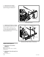
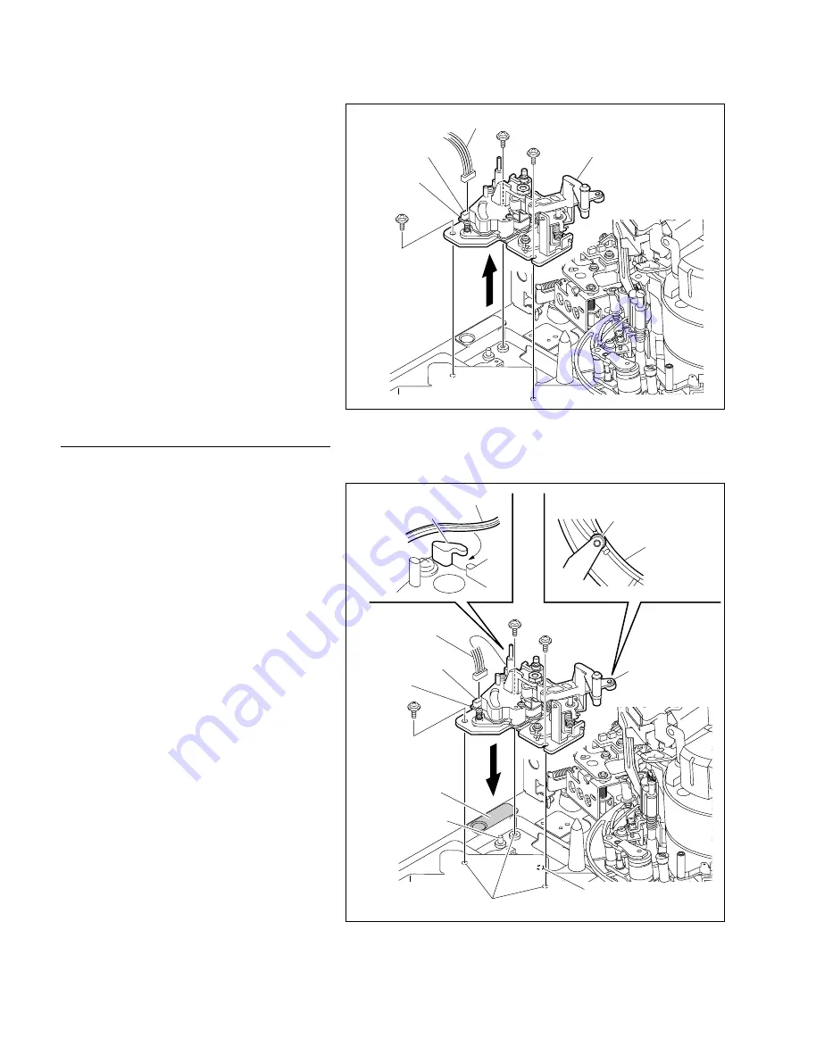
2. Removing the S Tension Regulator
Assembly
(1) Remove the three screws to remove the S
tension regulator assembly.
(2) Disconnect the harness from the connector
CN206 on the TR-119 board.
n
Be careful not to apply excessive force to the
board when removing the harness.
Installation
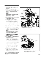
3. Attaching the S Tension Regulator
Assembly
(1) Clean the mounting surfaces between the S
tension regulator assembly and the MD base
assembly (three contact surfaces).
(2) Connect the harness to the connector CN206
on the TR-119 board.
(3) Hook the harness on the A portion of the S
tension regulator.
(4) Match the S tension regulator assembly with
the positioning pin and the positioning hole
of the MD base assembly then fasten with
three screws so that the roller portion comes
to the position as shown in the figure of the
threading ring assembly.
Tightening torque: 78.4
x
10
_
2
N
.
m
{8.0 kgf
.
cm}
(5) Check that the harness is not on the cassette
compartment mounting surface (shaded
portion in the figure).
4. Reattaching the S Plate
Reattach the S plate assembly.
(Refer to step 2 in Section 5-16-1.)
Remove the S Tension Regulator Assembly
Attach the S Tension Regulator Assembly


