5-115
SRW-5000/5500
CN61
CN62
P
W
B
CN205
CN204
PWB
Flat cable
Reel motor
Screw
Screw
Screw
MB-964 board
Power supply
harness
Flat cable
Reel motor
Flexible
boards
Flexible boards
DR-508 board (A side)
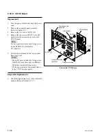
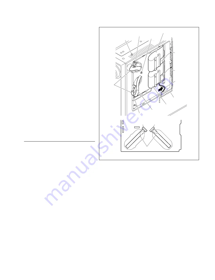
Fig. 1
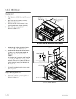
15. Close the DR-508 board and tighten the three
screws to fix it.
16. Connect the flexible boards that have been
disconnected in step 4 to the connectors on
the reel motors.
c
The connecting direction of the flexible board
is specified. When disconnecting the flexible
boards from both reel motor and DR-508
board, be sure to connect them so that the
character “PWB” on the flexible boards are
shown at the connector sides of the DR-508
board. (Fig. 1.) If connected opposite side,
the DR-508 board will fail.
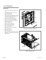
17. Connect the flat cables that have been
removed in step 3 to the connectors CN61
and CN62 on the MB-964 board.
18. Arrange the power supply harness between
the DR-508 board and MB-964 board in the
arrow direction.
19. Reattach the bottom plate.
(Refer to Section 1-3-2.)
Steps after Replacement
20. Perform the servo/DT system adjustment.
(Refer to Section 8-3.)
Connect the Flat Cables and Flexible Boards


