6-15
SRW-5000/5500
.
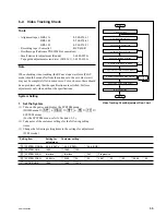
Alignment tape : HR2-1A
S802-1/SS-95 board : ON (Tracking VR : Enabled)
S802-3/SS-95 board : ON (DT operation : Stopped)
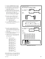
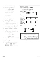
Spec.10 :
a
x
100
<
10 %
Fluctuation amount a at the entrance side is less
than 10 % of the maximum level A.
A
A
a
RF max
A = RF max
x
0.8
A
B
C
D
E
F
G
H
J
K
L
M
N
S802
RV1001 (Tracking VR)
P
1
2
<SS-95 board, side A>
A
B
C
D
E
F
G
H
J
K
L
M
N
P
1
2
TP52
TP5
<EQ-94 board, side A>
TP44
CH-1
<SRW-5000>: TP52/EQ-94 board (ADV AC ENV signal)
<SRW-5500>: TP44/EQ-94 board (CONF AC ENV signal)
CH-2
<SRW-5000/5500>: TP5/EQ-94 board (SWP5 signal)
TRIG: CH-2
CH-1
<SRW-5000>: TP52/EQ-94 board
<SRW-5500>: TP44/EQ-94 board
.
Connection of the oscilloscope
2. Adjust the HDCAM DT Head Contact
(1) Turn off the power, then remove the HR2-1B.
(2) Set the alignment tape HR2-1A and put a
weight (about 1 kg) onto it.
(3) Set Bit-1 and Bit-3 of the DIP switch S802 on
the SS-95 board to ON (upper side).
Bit-1 ON: The tracking control is enabled.
Bit-3 ON: The DT operation is stopped.
(4) Turn on the power, then playback the HR2-
1A in the PLAY mode.
(5) Rotate the tracking VR (RV1001/SS-95
board) clockwise so that the center portion of
the RF envelope waveform becomes 80 % of
the maximum output level.
(6) Check that the fluctuation amount at the
entrance side satisfies specification 10.
If specification 10 is not satisfied, perform
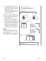
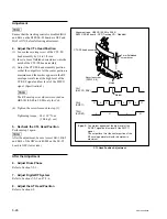
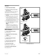
steps (9) to (16).
(7) Turn off the power, then remove the HR2-
1A.
(8) Reset Bit-1 and Bit-3 of the DIP switch S802
on the SS-95 board to OFF (lower side).
HDCAM DT Head Contact Adjustment


