6-39
SRW-5000/5500
Adjustment
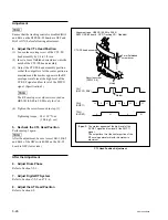
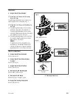
4. Adjust the TG-5 (Threading Roller) Height
(1) Play back the 1 kHz, 0 VU signal portion (00:00 to
15:00) on the HR2-1A.
(2) Set the REV
x
1 mode.
(3) Slightly press down the portion A of the tape shown in
figure, and check to see that the output level is not
increased.
If the level is increased, press the EJECT button to
unthread the tape, and then turn the upper flange of
TG-5 clockwise using a tape guide adjustment driver.
(4) Slightly push up the portion B of the tape, and check to
see that the output level is not increased.
If the level is increased, press the EJECT button to
unthread the tape, and then turn the upper flange of
TG-5 counterclockwise using the tape guide adjust-
ment driver.
CUE Level Adjustment in REV Mode
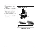
(5) Check the output level satisfies specification 1 of step
3.
If the specification 1 is not satisfied, repeat steps (1)
through (4) mentioned above.
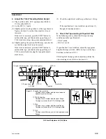
5. Check the Tape-running at Tape Exit Side
In the following modes, check that the tape-running
condition satisfies specification 2.
.
PLAY mode
.
REV
x
1 mode
If specification 2 is not satisfied, adjust the tape guides
height at the tape exit side. (Refer to step 5 (at the Tape
Exit Side) in Section 6-12-2.)
If the height of the tape guide is adjusted, perform the
video tracking check. (Refer to Section 6-2.)
B
A
TG-3
TG-4
AT head
Capstan
AT erase head
f
TG-4
Pinch roller
Cassette
d
Lead of drum exit side
e
TG-3 (Exit guide)
g
TG-5
Flange
Flange
Tape
Tape
Tape curl volume
Tape curl volume
d
e
f
g
Spec.2 :
Lead of drum exit side
The tape runs in contact with the drum lead and
without any curl at the lead.
TG-3 (Exit guide)
The tape runs in contact with the upper flange.
The tape curl is less than 1/10 of the tape width.
TG-4
The tape runs in contact with the lower flange.
The tape curl is less than 1/10 of the tape width.
TG-5
The tape runs without any curl at the upper and lower
flanges.


