8-29
SRW-5000/5500
SYNC Output Adjustment
5.
Connect the 75
Z
terminator to the SD OUT SYNC
connector, then connect the oscilloscope.
6.
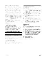
Check the waveform of the oscilloscope, then adjust
the pedestal level (C) and burst level (D).
Pedestal level
Adjusting point:
1
1003/VPR-79 (C-1)
Specification:
C = 0
±
5 mV
Burst level
Adjusting point:
1
1002/VPR-79 (C-1)
Specification:
D = 286
±
7 mV
7.
Exit the maintenance mode.
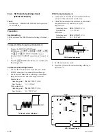
VPR-79 Board (Side A)
B
A
Composite output adjustment
8-6-3. SD Video Output Adjustment
(525/59.94 Hz Output)
Tools
.
Oscilloscope: TEKTRONIX TDS3054B or equivalent
.
75
Z
terminator
Preparation
1. System setting.
Set the system to the 1080/59.94i mode referring to
Section 8-1-3.
2. Check that the equipment has warmed up.
Before starting the adjustment, warm up the VTR and
other equipment by applying power to them for 30 minutes
or more.
Composite Video Output Level Adjustment
1.
Display the SD OUT ADJUST menu.
(HOME menu
→
[SFT]
+
[DIAG]
→
[SFT]
+
[F8]
→
[ALT]
→
[F6]
→
SD OUT ADJUST menu)
(For the SD OUT ADJUST menu, refer to Section 3-4-
4.)
2.
Press the
[F2]
(VIDEO LEVEL) key several times for
the setting to ON.
Composite Output Adjustment
3.
Connect the 75
Z
terminator to the SD OUT COM-
POSITE connector, then connect the oscilloscope.
4.
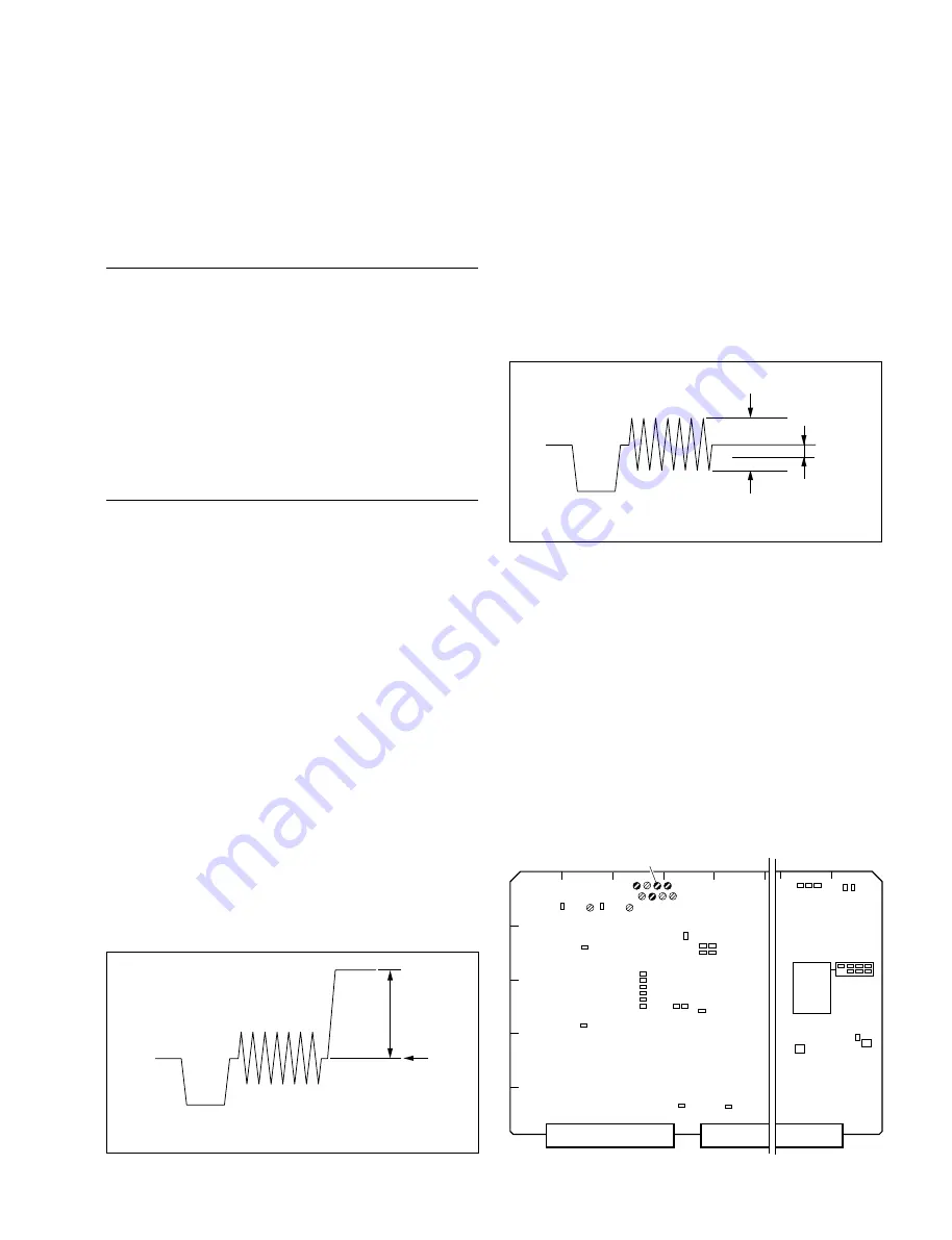
Check the waveform of the oscilloscope, then adjust
the pedestal level (A) and video output level (B).
Pedestal level
Adjusting point:
1
1001/VPR-79 (D-1)
Specification:
A = 0
±
5 mV
Video output level
Adjusting point:
1
1000/VPR-79 (C-1)
Specification:
B = 714
±
7 mV
SYNC output adjustment
C
GND
D
A
E
F
G
H
1
2
3
4
5
J
K
RV1000
RV1001
RV1002
RV1003
B
C
D
RV1200
RV1201
TP1000
TP1001
TP1002
TP1003
TP1004
TP1005
TP1006
TP1007
TP1008
TP1009
TP1200
TP1201
TP1202
TP800
TP801
TP900
TP901
E2000
E2001
E2005
TP100
TP1300
TP1301
TP1302
TP1303
TP1304
TP1305
TP1306
TP1307
TP1308
TP301
E2002
E2007
S100
S700


