background image

Getting Star

ted

masterpage:Right

lename[C:\Data\Sony SEM_Janet\STR-

DE597_Data\J904000_4252271121DE597UCA\4252271121\4252271121DE597UCA\GB03CO
N_STR-DE597-UCA.fm]

 model name1[STR-DE597]

[4-252-271-12(1)]

17

GB

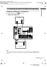
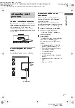
Setting the voltage selector

If your receiver has a voltage selector on the rear 
panel, check that the voltage selector is set to the 
local power supply voltage. If not, use a 
screwdriver to set the selector to the correct 
position before connecting the AC power cord to 
a wall outlet.

Connecting the AC power 
cord

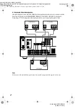
Connect the AC power cord to a wall outlet.

Performing initial setup 
operations

Before using the receiver for the first time, 
initialize the receiver by performing the 
following procedure.
This procedure can also be used to return 
settings you have made to their factory defaults. 
Use the buttons on the receiver for the operation.

1

Press 

?/1

 to turn off the receiver.

2

Hold down 

?/1

 for 5 seconds.

“PUSH” and “ENTER” appears in the 
display alternatingly.

3

Press ENTER.

“CLEARING” appears in the display for a 
while, then “CLEARED” appears.
The following are reset to their factory 
settings.
• All settings in the SET UP, LEVEL, 

TONE and CUSTOMIZE menus.

• The sound field memorized for each 

input and preset station.

• All sound field parameters.
• All preset stations.
• All index names for inputs and preset 

stations.

• MASTER VOLUME –/+ is set to “VOL 

MIN”.

• Input is set to DVD.

4: Connecting the AC 
power cord

120V

220V

240V

VOLTAGE SELECTOR

NTER

L

+

+

UND BACK

L

b

To a wall 
outlet

AC power cord

GB01COV_STR-DE597-UCA.book  Page 17  Monday, March 8, 2004  12:15 PM

Summary of Contents for ST-RDE597

Page 1: ...04 Sony Corporation 4 252 271 12 1 FM Stereo FM AM Receiver Operating Instructions Owner s Record The model and serial numbers are located on the rear of the unit Record the serial number in the space provided below Refer to them whenever you call upon your Sony dealer regarding this product Model No Serial No STR DE597 GB01COV_STR DE597 UCA book Page 1 Monday March 8 2004 12 15 PM ...

Page 2: ...ctions may cause harmful interference to radio communications However there is no guarantee that interference will not occur in a particular installation If this equipment does cause harmful interference to radio or television reception which can be determined by turning the equipment off and on the user is encouraged to try to correct the interference by one or more of the following measures Reor...

Page 3: ... of your remote see pages 42 45 This receiver incorporates Dolby Digital and Pro Logic Surround and the DTS Digital Surround System Manufactured under license from Dolby Laboratories Dolby Pro Logic and the double D symbol are trademarks of Dolby Laboratories DTS DTS ES Neo 6 and DTS 96 24 are trademarks of Digital Theater Systems Inc About area codes The area code of the receiver you purchased is...

Page 4: ... radio stations 25 Using the Radio Data System RDS 26 Models of area code CEL CEK only Changing the display 27 About the indications in the display 28 Enjoying Surround Sound Using only the front speakers 30 Enjoying higher fidelity sound 30 AUTO FORMAT DIRECT Selecting a sound field 31 Selecting the surround back decoding mode 33 SURR BACK DECODING Advanced Adjustments and Settings Switching the ...

Page 5: ... to output the audio decoded by the component s internal multi channel decoder through this receiver c Model equipped only with AUDIO OUT L R jacks etc d Model with component video Y PB CB B Y PR CR R Y input jacks Getting Started 1 Check how to hookup your components Component to be connected Page DVD player With digital audio outputa 7 8 With multi channel audio outputb 10 11 With analog audio o...

Page 6: ... audio cord Black Tip Audio cord A can be torn into two monaural audio cords F G Component video cord Except for models of area code CEL CEK Green Blue Red Notes Turn off the power to all components before making any connections Be sure to make connections firmly to avoid hum and noise When connecting an audio video cord be sure to match the color coded pins to the appropriate jacks on the compone...

Page 7: ...o not connect the TV s video output jack to the VIDEO 2 VIDEO IN jack on the receiver 1a Connecting components with digital audio output jacks VIDEO 1 MULTI CH IN FRONT CENTER SUB WOOFER SURROUND VIDEO IN AUDIO IN AUDIO OUT VIDEO IN VIDEO OUT DVD IN VIDEO 2 IN MONITO OUT VIDEO 2 AUDIO IN MONITOR COMPONENT VID SA CD CD IN DVD IN MD TAPE SA CD CD L R L R SUB WOOFER L R OUT IN IN VIDEO IN DVD AM AUDI...

Page 8: ...eo signals cannot be converted to component video signals or vice versa VIDEO 1 MULTI CH IN FRONT CENTER SUB WOOFER SURROUND VIDEO IN AUDIO IN AUDIO OUT FRONT B VIDEO IN VIDEO OUT DVD IN VIDEO 2 IN MONITOR OUT VIDEO 2 AUDIO IN MONITOR COMPONENT VIDEO SA CD CD IN DVD IN COAXIAL SPEA Y PB CB B Y PR CR R Y MD TAPE SA CD CD L R L R SUB WOOFER L R OUT IN IN VIDEO IN DVD AM AUDIO IN L R L R AUDIO OUT VI...

Page 9: ...er Audio CD player connected to the SA CD CD OPTICAL IN jack on this receiver Connect to the analog input jacks SA CD CD IN jacks Refer to the operating instructions supplied with the Super Audio CD player VIDEO 1 MULTI CH IN FRONT CENTER SUB WOOFER SURROUND VIDEO IN AUDIO IN AUDIO OUT VIDEO IN VIDEO OUT DVD IN VIDEO 2 IN MONITO OUT VIDEO 2 AUDIO IN MONITOR COMPONENT VIDE DVD IN COAXIAL MD TAPE SA...

Page 10: ... other than the Dolby Digital and DTS Note When you make connections to the MULTI CH IN jacks you will need to adjust the level of the surround speakers and sub woofer using the controls on the connected component 1b Connecting components with multi channel output jacks VIDEO 1 FRONT CENTER SUB WOOFER SURROUND VIDEO IN AUDIO IN AUDIO OUT FRONT B VIDEO IN VIDEO OUT DVD IN VIDEO 2 IN MONITOR OUT VID...

Page 11: ... On this receiver the standard video signals cannot be converted to component video signals or vice versa VIDEO 1 MULTI CH IN FRONT CENTER SUB WOOFER SURROUND VIDEO IN AUDIO IN AUDIO OUT FRONT B VIDEO IN VIDEO OUT DVD IN VIDEO 2 IN MONITOR OUT VIDEO 2 AUDIO IN MONITOR COMPONENT VIDEO SA CD CD IN DVD IN COAXIAL SPEA Y PB CB B Y PR CR R Y MD TAPE SA CD CD L R L R SUB WOOFER L R OUT IN IN VIDEO IN DV...

Page 12: ...audio jacks VIDEO 1 MULTI CH IN FRONT CENTER SUB WOOFER SURROUND VIDEO IN AUDIO IN AUDIO OUT VIDEO IN VIDEO OUT DVD IN VIDEO 2 IN MONITO OUT VIDEO 2 AUDIO IN MONITOR COMPONENT VID SA CD CD IN DVD IN MD TAPE SA CD CD L R L R SUB WOOFER L R OUT IN IN VIDEO IN DVD AM AUDIO IN AUDIO OUT VIDEO OUT L R L DIGITAL ANTENNA OPTICAL COAXIAL VIDEO 2 IN A LINE L R OUTPUT LINE L R LINE INPUT OUTPUT A l IN A l O...

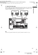
Page 13: ...cords A G see page 6 MULTI CH IN FRONT CENTER SUB WOOFER SURROUND VIDEO IN AUDIO IN AUDIO OUT VIDEO IN VIDEO OUT DVD IN VIDEO 2 IN MONITO OUT VIDEO 2 AUDIO IN MONITOR COMPONENT VID SA CD CD IN DVD IN MD TAPE SA CD CD L R SUB WOOFER L R OUT IN IN VIDEO IN DVD AM AUDIO IN AUDIO OUT VIDEO OUT R R L DIGITAL ANTENNA OPTICAL COAXIAL VIDEO 2 IN IN VIDEO OUT AUDIO OUT VIDEO IN AUDIO IN OUTPUT INPUT L B VI...

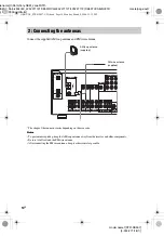
Page 14: ...ponents Be sure to fully extend the FM wire antenna After connecting the FM wire antenna keep it as horizontal as possible 2 Connecting the antennas VIDEO 1 MULTI CH IN FRONT CENTER SUB WOOFER SURROUND VIDEO IN AUDIO IN AUDIO OUT VIDEO IN VIDEO OUT DVD IN VIDEO 2 IN MONITO OUT VIDEO 2 AUDIO IN MONITOR COMPONENT VIDE SA CD CD IN DVD IN COAXIAL MD TAPE SA CD CD L R L R SUB WOOFER L R OUT IN IN VIDEO...

Page 15: ...enjoy high fidelity reproduction of DVD software recorded in the Surround EX format if you connectoneadditionalsurroundbackspeaker 6 1channel see Selectingthesurroundbackdecoding mode on page 33 Example of 6 1 channel speaker system configuration Tips When you connect 6 1 channel speaker system place the surround back speaker behind the listening position Since the sub woofer does not emit highly ...

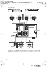
Page 16: ...ls You can select the front speakers you want to use with the SPEAKERS OFF A B A B button For details see Selecting the speaker system page 40 AUDIO OUT FRONT B CENTER EO 2 N MONITOR OUT NENT VIDEO SPEAKERS Y PB CB B Y PR CR R Y SUB WOOFER L R L R L R SURROUND BACK AC OUTLET A E e A E e A E e E e A INPUT AUDIO IN B E e A SPEAKERS FRONT B E e A SURROUND FRONT A L R Sub woofer Center speaker Surroun...

Page 17: ...rming the following procedure This procedure can also be used to return settings you have made to their factory defaults Use the buttons on the receiver for the operation 1 Press 1 to turn off the receiver 2 Hold down 1 for 5 seconds PUSH and ENTER appears in the display alternatingly 3 Press ENTER CLEARING appears in the display for a while then CLEARED appears The following are reset to their fa...

Page 18: ...pplied Easy Setup Guide x S W XXX SUB WOOFER Sub woofer selection YES If you connect a sub woofer select YES NO If you did not connect a sub woofer select NO The front speakers are automatically set to LARGE and you cannot change this setting This activates the bass redirection circuitry and outputs the LFE signals from other speakers In order to take full advantage of the Dolby Digital bass redir...

Page 19: ...hem if possible Therefore even when using small speakers you can set them to LARGE if you want to output the bass frequencies from that speaker On the other hand if you are using a large speaker but prefer not to have bass frequencies output from that speaker set it to SMALL If theoverall soundlevel is lower thanyouprefer set all speakersto LARGE Ifthereisnot enoughbass you can use the BASS parame...

Page 20: ...ill cause a delay in the output of the sound from that speaker In other words the speaker will sound like it is further away For example setting the center speaker distance 1 2 meters 3 6 feet closer than the actual speaker position will create a fairly realistic sensation of being inside the screen If you cannot obtain a satisfactory surround effect because the surround speakers are too close set...

Page 21: ... sound of the front speakers If you are not sure which sounds best select BEHD LO or BEHD HI and then use the speaker distance parameter and speaker level adjustments to obtain proper balance Adjust the speaker levels and balance while listening to the test tone from your listening position Use the remote for the operation Tip The receiver employs a test tone with a frequency centered at 800 Hz 1 ...

Page 22: ... MUTING on the remote The muting function will be canceled when you do the following Press MUTING on the remote again Turn the power off Increase the volume To use the headphones Connect the headphones to the PHONES jack When the headphones are connected speaker output is automatically canceled and SP A and SP B do not light up in the display When the headphones are connected you can select only t...

Page 23: ...iver see page 14 Tip The tuning scale differs depending on the area code as showninthefollowingtable For detailsonareacodes see page 3 The AM tuning scale can be changed see page 51 Automatic tuning If you do not know the frequency of the station you want you can let the receiver scan all available stations in your area 1 Press TUNER FM AM repeatedly to select the FM or AM band The last received s...

Page 24: ...nt to store FM or AM stations one by one see Presetting radio stations page 25 Use the buttons on the receiver for the operation 1 Press 1 1 1 1 to turn off the receiver 2 Hold down MEMORY and press 1 1 1 1 to turn the receiver back on AUTO BETICAL SELECT appears in thedisplayandthereceiverscansandstores all the FM and FM RDS stations in the broadcast area For RDS stations the tuner first checks f...

Page 25: ...a preset station number Press SHIFT repeatedly to select a memory page A B or C and then press the numeric buttons to select a preset number 5 Press MEMORY again The station is stored to the selected preset number If MEMORY goes out before you press MEMORY start again from step 3 6 Repeat steps 2 to 5 to preset another station Tuning to preset stations 1 Press TUNER FM AM repeatedly to select the ...

Page 26: ...d field currently applied a Type of program being broadcast see page 26 b Text messages sent by the RDS station Notes If there is an emergency announcement by government authorities ALARM flashes in the display When the message consists of 9 characters or more the message scrolls across the display Ifastationdoesnot provideaparticularRDSservice NO XXXX such as NO TEXT appears in the display Descri...

Page 27: ... the input or preset station page 39 Index name does not appear when only blank spaces have been entered or it is the same as the input name During RDS reception only Models of area code CEL CEK only See page 26 Adjusting the brightness of the display Press DIMMER repeatedly The brightness of the display will change in 3 steps PHONE IN Programs where members of the public express their views by ph...

Page 28: ...r and surround speakers are set to NO and A F D AUTO DOLBY PL PLII MOV or PLII MUS is selected Note Dolby Pro Logic and Dolby Pro Logic II decoding do not function for DTS format signals F DTS ES 96 24 DTS lights up when DTS signals are input DTS ES lights up when DTS ES signals are input DTS 96 24 lights up when the receiver is decoding DTS 96 kHz 24 bit signals Note WhenplayingaDTSformat disc be...

Page 29: ...e letters vary to show how the receiver downmixes the source sound based on the speakers settings L Front Left R Front Right C Center monaural SL Surround Left SR Surround Right S Surround monaural or the surround components obtained by Pro Logic processing SB Surround Back the surround back components obtained by 6 1 channel decoding Example Recording format Front Surround 3 2 Output channel Surr...

Page 30: ...ode you want for your audio sound Decoding the input audio signal automatically In this mode the receiver automatically detects the type of audio signal being input Dolby Digital DTS standard 2 channel stereo etc and performs the proper decoding if necessary This mode presents the sound as it was recorded encoded without adding any surround effects However if there are no low frequency signals Dol...

Page 31: ...al is 2 channel stereo or if the source signal does not include a LFE signal thereceiver generatesalowfrequencysignal for output to the sub woofer However the low frequency signal is not generated when Neo 6 Cinema or Neo 6 Music is selected You can take advantage of surround sound simply by selecting one of the receiver s pre programmed sound fields They bring the exciting and powerful sound of m...

Page 32: ...ay x HALL Reproduces the acoustics of a classical concert hall x JAZZ JAZZ CLUB Reproduces the acoustics of a jazz club x CONCERT LIVE CONCERT Reproduces the acoustics of a 300 seat live house When the headphones are connected You can select only from the following sound fields x HP 2CH HEADPHONE 2CH Outputs the sound in 2 channel stereo Standard 2 channel stereo sources completely bypass the soun...

Page 33: ...set to SMALL HALL JAZZ CLUB LIVE CONCERT This function lets you select the decoding mode for the surround back signals of the multi channel input stream By decoding the surround back signal of DVD software etc recorded in Dolby Digital EX DTS ES Matrix DTS ES Discrete 6 1 etc format you can enjoy the surround sound intended by the filmmakers Press SURR BACK DECODING repeatedly to select the surrou...

Page 34: ...th Surround EX and 5 1 channel signals d Software encoded with both 5 1 channel signals and an extension stream designed for returning those signals to 6 1 discrete channels Discrete 6 1 channel signals are DVD specific signals not used in movie theaters e This decoder can be used for all 6 1 formats Dolby Digital EX DTS ES Matrix 6 1 DTS ES Discrete 6 1 Note Theremaybenosoundfromthesurroundbacksp...

Page 35: ...tup items you can adjust in each menu vary dependingonthesoundfield Certainsetupparameters may be dimmed in the display This means that the selected parameter is either unavailable or fixed and unchangeable Adjusting the LEVEL menu You can adjust the balance and level of each speaker These settings are applied to all sound fields except for effect level parameter The effect level parameter setting...

Page 36: ...ineer MAX The dynamic range is compressed dramatically Tip Dynamic range compressor lets you compress the dynamicrangeof thesoundtrackbasedonthe dynamic rangeinformationincludedinthe DolbyDigital signal We recommend using the MAX setting This greatly compresses the dynamic range and lets you view movies late at night at low volumes Unlike analog limiters the levels are predetermined and provide a ...

Page 37: ...rom 6 dB to 6 dB in 1 dB steps Using the CUSTOMIZE menu to adjust the receiver You can adjust various receiver settings using the CUSTOMIZE menu 1 Press MAIN MENU repeatedly to select CUSTOM 2 Press or repeatedly to select the parameter you want to adjust For details see CUSTOMIZE menu parameters below 3 Press or repeatedly to select the setting you want The setting is entered automatically 4 Repe...

Page 38: ...other signals are input the sound is output However this receiver cannot decode DTS CD when set to DEC PCM Note When set to DEC AUTO and the sound from the digital audio jacks for CD etc is interrupted when playback starts set to DEC PCM x DUAL XXX Digital broadcast language selection Lets you select the language you want to listen to during digital broadcast This feature only functions for Dolby ...

Page 39: ...ENTER The cursor flashes and you can select a character 5 Use or and or to create an index name Press or repeatedly to select a character then press to move the cursor to the next position Tips You can select the character type as follows by pressing or repeatedly Alphabet upper case tNumbers tSymbols To enter a blank space press or repeatedly until a blank space appears in the display If you made...

Page 40: ...he remaining time appears in the display If you press SLEEP again the sleep timer will be canceled You can select the front speaker system you want to use Press SPEAKERS OFF A B A B repeatedly to select the front speaker system you want to use The selected speaker system appears in the display To turn off the speaker output press SPEAKERS OFF A B A B repeatedly until SP A and SP B indication turn ...

Page 41: ...dio sources when editing a video tape Seetheoperatinginstructionsof your VCR or DVD player if you need help 1 Select the program source to be recorded 2 Prepare the component for playing Forexample insertavideotapeyouwantto record into VCR 3 Insert a blank video tape into the VCR VIDEO 1 for recording 4 Start recording on the recording VCR then start playing the video tape or DVD you want to recor...

Page 42: ...emelyhot orhumid place Do not use a new battery with an old one Do not expose the remote sensor to direct sunlight or lighting apparatuses Doing so may cause a malfunction If you don t use the remote for an extended period of time remove the batteries to avoid possible damage from battery leakage and corrosion Operations Using the Remote RM U306B Before you use your remote e e E E Remote button de...

Page 43: ...menu of the receiver MASTER VOL qg Receiver Adjusts the master volume of the receiver MD TAPE wk Receiver To listen to Minidisc or audio tape MENU ql Receiver Selects a menu item Remote Button Operations Function MENU qk Receiver Adjusts or changes the setting MOVIE MUSIC qa Receiver Selects the pre programmed sound fields for movie and music MULTICH qs Receiver Selects MULTI CH IN source MUTING q...

Page 44: ...layer MD deck DAT deck Selects track numbers 0 selects track 10 TV VCR Satellite tuner Selects channel numbers 2CH wa Receiver Selects 2CH STEREO mode 10 wh CD player VCD player LD player MD deck Selects track numbers over 10 wh TV Selects the channel entry mode either one or two digit 1 2 Receiver Turnsthereceiveronor off wg VCR CD player VCD player LD player DVD player MD deck DAT deck Tape deck...

Page 45: ... button of the component you want to assign to the input button for example 4 Tape deck Thefollowingbuttonsareassignedtoselect the input Sony VCRs are operated with a VTR 1 2 or 3 setting These correspond to Beta 8mm and VHS respectively Now you can use the MD TAPE button to control the tape deck To reset a button to its factory setting Repeat the above procedure To reset all the input buttons to ...

Page 46: ...rdmust bechangedonlyat thequalified service shop On heat buildup Althoughthe receiver heats upduringoperation this is not amalfunction Ifyoucontinuouslyusethis receiver at a large volume the cabinet temperature of the top side and bottom rises considerably To avoid burning yourself do not touch the cabinet On placement Place the receiver in a location with adequate ventilation to prevent heat buil...

Page 47: ...ound from analog 2 channel sources Check that the INPUT MODE is not set to COAX IN or OPT IN page 35 Check that you have not selected MULTI CH IN There is no sound from digital sources from COAXIAL or OPTICAL input jack Check that the INPUT MODE is not set to ANALOG page 35 Check that the INPUT MODE is not set to COAX IN for the sources fromOPTICALinput jack or set to OPT IN for the sources from C...

Page 48: ...n external antenna if necessary The signal strength of the stations is too weak whentuninginwithautomatictuning Usedirect tuning Make sure you set the tuning interval correctly when tuning in AM stations with direct tuning No stations have been preset or the preset stations have been cleared when tuning by scanning preset stations Preset the stations page 25 Press DISPLAY repeatedly so that the fr...

Page 49: ...r nearest Sony dealer Reference sections for clearing the receiver s memory AUDIO POWER SPECIFICATIONS POWER OUTPUT AND TOTAL HARMONIC DISTORTION Models of area code U only With 8 ohm loads both channels driven from 20 20 000 Hz rated 90 watts per channel minimum RMS power with no more than 0 09 total harmonic distortion from 250 milliwatts to rated output Amplifier section Power Output Models of ...

Page 50: ...W 8 ohms 1 kHz THD 10 FRONT2 120 W ch CENTER2 120 W SURR2 120 W ch SURR BACK2 120 W 1 Measured under the following conditions 2 Depending on the sound field settings and the source there may be no sound output 3 Measured under the following conditions Frequency response Inputs Analog 4 INPUT SHORT with sound field and tone bypassed 5 Weighted network input level Inputs Digital Outputs Analog Tone ...

Page 51: ...distortion 0 5 50 mV m 400 Hz Selectivity At 9 kHz 35 dB At 10 kHz 40 dB 6 You can change the AMtuning scale to 9 kHz or 10 kHz After tuning in any AM station turn off the receiver While holding down PRESETTUNING orTUNING press 1 All preset stationswill be erased when you change the tuning scale To reset the scale to 10 kHz or 9 kHz repeat the procedure Video section Inputs Outputs Video 1 Vp p 75...

Page 52: ...23 MULTI CH IN 9 23 MUSIC button indicator qd 32 47 48 PHONES jack ea 22 47 PRESET TUNING wj 25 51 SA CD CD ws 22 SPEAKERS OFF A B A B 2 16 40 47 SURR BACK DECODING qf 33 TUNER FM AM wa 22 23 24 25 39 TUNING wk 23 51 VIDEO 1 wh 22 VIDEO 2 wg 22 2CH button indicator q 30 32 36 1 power 1 17 18 24 36 51 ql 18 35 37 39 qk 18 35 37 39 List of button locations and reference pages How to use this page Us...

Page 53: ...o 38 Dubbing See Recording E Editing See Recording I Indexing See Naming L Labeling See Naming LEVEL menu 35 N Naming 39 P Preset stations how to 25 how to tune 25 R RDS 26 Recording on a video tape 41 on an audio tape or MD 41 S Selecting component 22 front speaker system 40 sound field 31 33 SET UP menu 18 Sleep Timer 40 Sound field customizing 35 pre programmed 31 33 resetting 36 selecting 31 3...

Page 54: ...GB01COV_STR DE597 UCA book Page 54 Monday March 8 2004 12 15 PM ...

Page 55: ...GB01COV_STR DE597 UCA book Page 55 Monday March 8 2004 12 15 PM ...

Page 56: ...Janet STR DE597_Data J904000_4252271121DE597UCA 4252271121 4252271121DE597UCA GB10BK C_STR DE597 UCA fm Sony Corporation Printed in Malaysia model name1 STR DE597 4 252 271 12 1 GB01COV_STR DE597 UCA book Page 56 Monday March 8 2004 12 15 PM ...

Reviews: