88
STR-DA2000ES/DB2000
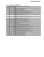
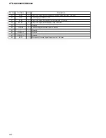
Pin No.
Pin Name
I/O
Description
89
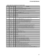
A/D-RST
O
Reset signal output to the A/D converter “H”: reset
90
DSD-RST
O
DSD reset signal output terminal “H”: reset
91
FS
I
Clock signal input from the GPR
92
DAC-RESET
O
D/A converter reset signal output terminal “L”: reset
93
DAC-LAT
O
Serial data latch pulse signal output to the D/A converter
94
DAC-CLK
O
Serial data transfer clock signal output to the D/A converter
95
UCOM-DATAOUT
O
Serial data output to the D/A converter
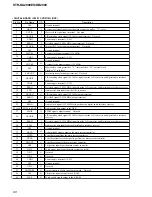
96
DAC-DATAOUT
I
Serial data input from the D/A converter
97
VCC
—
Power supply terminal (+3.3V)
98
VSS
—
Ground terminal
99
EEPROM-SDA
I/O
Two-way data bus with the EEPROM
100
EEPROM-SCL
O
Serial data transfer clock signal output to the EEPROM
101
VSS
—
Ground terminal
102
NC
I
Not used
103
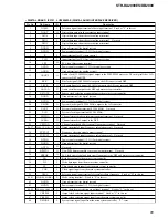
OSD-VSYNC
O
Vertical sync signal input terminal (STR-DB2000 only)
104
XCLKSEL
O
NTSC/PAL selection signal output terminal “L”: NTSC, “H”: PAL
(STR-DB2000 only)
105
OSD-CLK
O
Serial data transfer clock signal output to the OSD driver
106
OSD-DATA
O
Serial data output to the OSD driver
107
OSD-LAT
O
Serial data latch pulse signal output to the OSD driver
108
NC
I
Not used
109
SOT1
O
Serial data output to the RS-232C (STR-DA2000ES only)
110
SIN1
I
Serial data input from the RS-232C (STR-DA2000ES only)
111 to 113
NC
I
Not used
114 to 117
V-SW1 to V-SW4
O
Video selection signal output terminal
118, 119
SFCF2, SFCF1
O
DC cut filter on/off and cut off frequency selection signal output to the DC cut digital filter
120, 121
TP
O
Not used
122
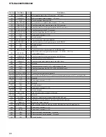
VCC
—
Power supply terminal (+3.3V)
123 to 125
NC
O
Not used
126
VSS
—
Ground terminal
127 to 129
VCC
—
Power supply terminal (+3.3V)
130, 131
VSS
—
Ground terminal
132, 133
AD1, AD2
I
Front key panel input terminal (A/D input)
134, 135
NC
I
Not used
136
12VTRIG
O
Trigger out signal output terminal (STR-DA2000ES only)
137
SB SEL
O
Audio data (for surround back) selection signal output terminal
138
VERSION
I
Destination setting terminal
139
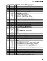
RDS-SIGNAL
I
RDS signal input from the tuner unit (STR-DB2000: AEP and UK models only)
140
VCC
—
Power supply terminal (+3.3V)
141
VCC2
—
Power supply terminal (+3.3V)
142
X0A
I
Sub system clock input terminal Not used
143
X1A
O
Sub system clock output terminal Not used
144
VSS
—
Ground terminal
Summary of Contents for STR-DA2000ES - Fm Stereo/fm-am Receiver
Page 152: ...STR DA2000ES DB2000 12 12 MEMO ...

