STR-DA2400ES/DG920
104
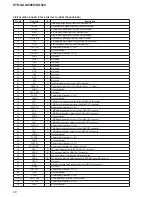
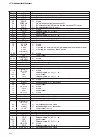
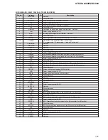
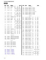
Pin No.
Pin Name
I/O
Description
116
AVRH
(STANDARD PS A/D)
I
Reference voltage (+3.3V) input terminal (for A/D converter)
117
HDMI_SDA
I/O
I2C data bus with the HDMI controller
118
HDMI_SCL
O
I2C clock signal output to the HDMI controller
119
SIRCS-IN
I
SIRCS signal input from the remote control receiver
120
NO USE
O
Not used
121
CEC_DV/M
I
CEC serial data input from the HDMI connector
122
NO USE
O
Not used
123
ZONE_SEL
I
Zone selection signal input terminal Not used
124
VIDEO_DAC_RESET
O
Reset signal output terminal for the D/A converter (for video section) "L": reset
125
VIDEO_DAC_SDA
I
Power detection signal input from the video processor
126
RST_TRG
O
Reset signal output terminal for the system controller "L": reset
127
MD3
-
Mode setting terminal Fixed at "L" in this set
128
MD2
I
Serial data input terminal
129, 130
MD1, MD0
-
Mode setting terminal Fixed at "L" in this set
131
INITX
I
System reset signal input from the reset signal generator "L": reset
For several hundreds msec. after the power supply rises, "L" is input, then it changes to "H"
132
VSS_(GND)
-
Ground terminal
133
VCC5_(5V)
-
Power supply terminal (+3.3V)
134
RS232C_MIN
I
Serial data input from the RS-232C connector
135
RS232C_MOUT
O
Serial data output to the RS-232C connector
136
FLI_RESET
O
Reset signal output to the fl ash memory and video processor "L": reset
137
XM_XM/M
I
Serial data input from the XM receiver (DA2400ES/DG920: US model only)
138
XM_M/XM
O
Serial data output to the XM receiver (DA2400ES/DG920: US model only)
139
XM_RESET
O
Reset signal output to the XM receiver "L": reset (DA2400ES/DG920: US model only)
140
FLI_TX
I
UART communication transfer data input from the video processor
141
FLI_RX
O
UART communication transfer data output to the video processor
142
FLI_BUSY
I
Busy signal input from the video processor
143
SPI0_MISO
I
Serial data input from the serial fl ash and DSP
144
SPI0_MOSI
O
Serial data output to the serial fl ash and DSP
145
SPI0_CLK
O
Serial data transfer clock signal output to the serial fl ash and DSP
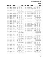
146
VSS_(GND)
-
Ground terminal
147
VCC5_(5V)
-
Power supply terminal (+3.3V)
148
SIRIUS_TX
I
Serial data input from the SIRIUS socket (DA2400ES: US model only)
149
SIRIUS_RX
O
Serial data output to the SIRIUS socket (DA2400ES: US model only)
150
FL_CLR
O
Blanking period signal output to the fl uorescent indicator tube
151
FL_LAT
O
Serial data latch pulse signal output to the fl uorescent indicator tube
152
FL_DATA
O
Serial data output to the fl uorescent indicator tube
153
FL_CLK
O
Serial data transfer clock signal output to the fl uorescent indicator tube
154
DMUART_DM/M
I
Serial data input from the DMPORT connector
155
DMUART_M/DM
O
Serial data output to the DMPORT connector
156
HDMI_VSYNC
I
Vertical sync signal input terminal Not used
157
DAC_CLK_SEL
O
Clock control signal output to the frequency multiplier for D/A converter (for video section)
158 to 160
NO USE
O
Not used
161
VSS_(GND)
-
Ground terminal
162
VCC5_(5V)
-
Power supply terminal (+3.3V)
163
NO USE
O
Not used
164
DSP_INT
I
Interrupt signal input from the DSP
165
RDS_CLK
I
RDS serial data transfer clock signal input from the tuner (FM/AM)
(DA2400ES: AEP, Continental European, East European, Russian and UK models only)
166, 167
232C-SEL1,
232C-SEL2
O
Data selection signal output terminal Not used
168
FSRATE1
I
L/R sampling clock signal input from the digital audio interface receiver or HDMI receiver
169
FUNC_LAT
O
Serial data latch pulse signal output to the audio input selector
170
STOP
I
AC off detection signal input terminal "L": AC off
171
POW_RY
O
Relay drive signal (for main power) output terminal "H": relay on
172
PROTECTOR
I
Protect detection signal input terminal
173
NO USE
-
Not used
174
EEPROM_SDA
I/O
Two-way data bus with the EEPROM
175
EEPROM_SCL
O
Serial data transfer clock signal output to the EEPROM
176
VCC5_(5V)
-
Power supply terminal (+3.3V)
Summary of Contents for STR DA2400ES - 7.1 Channel Home Theater AV Receiver
Page 26: ...STR DA2400ES DG920 26 MEMO ...

