56
STR-DE1075
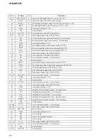
Pin No.
Pin Name
I/O
Description
90
PM1
O
PLL initialize signal output to the audio DSP1 (IC1501)
91
ADC : RST
O
Reset signal output to the A/D converter (IC1101)
92
DACINT
O
Reset signal output to the D/A converter (IC1201)
93
DA1LAT
O
Serial data latch pulse output to the D/A converter (IC1201)
94
(PG3) DACCLK
O
Serial data transfer clock signal output to the D/A converter (IC1201, 1202)
95
(PG4) DACDI
O
Serial date output to the D/A converter (IC1201, 1202)
96
(PG5) 2EXLOCK
O
Extarnal lock signal output to the audio DSP2 (IC1601)
97
VCC
—
Power supply terminal (+3.3V)
98
VSS
—
Ground terminal
99
EEPROM SDA
I/O
Two-way data bus with the EEPROM (IC1701)
100
EEPROM SCL
O
Serial data transfer clock signal output to the EEPROM (IC1701)
101
VSS
—
Ground terminal
102
HCLK
O
Host clock signal output to the audio DSP1, 2 (IC1501, 1601)
103
HDIN
O
Host serial data output to the audio DSP1, 2 (IC1501, 1601)
104
HDOUT2
I
Host serial data input from the audio DSP2 (IC1601)
105
CLK
O
OSD serial data transfer clock signal output to the select switch (IC307)
106
DATA
O
OSD serial data output to the select switch (IC307)
107
LAT
O
OSD serial data latch pulse output to the select switch (IC307)
108
DAIDO
I
Serial data input from the D/A converter (IC1201)
109
SOTI
O
UART signal output terminal Not used (fixed at “L”)
110
SIN1
I
UART signal input terminal Not used (fixed at “L”)
111
CLK
O
Serial data transfer clock signal output to the FL display driver (IC1601)
112
DIN
O
Serial data output to the FL display driver (IC1601)
113
LAT
O
Serial data latch pulse output to the FL display driver (IC1601)
114
CLR
O
Clear signal output to the FL display driver (IC1601)
115
VOL IC LAT
O
Serial data latch pulse output to the electrical volume (IC401, 501, 601, 701)
116
SYSTEM MUTE
O
System muting control signal output terminal
117
AC MUTE
O
Audio muting control signal output to the poweramp (IC403, 503, 603)
118
PROTECTOR
I
Over load detection signal input from the protect circuit “L”: protect detect
119
DA2LAT
O
Serial data latch pulse output to the A/D, D/A converter (IC1202)
120
CD DIRECT
O
CD direct relay drive signal output terminal Not used (open)
121
ANALOG DIGITAL
O
Analog/digital select signal output to the TC7WH157FU (IC1407)
“L”: analog, “H”: digital
122
VCC
—
Power supply terminal (+3.3V)
123
A. DIRECT
O
MULT/2CH DIRECT select signal output terminal Not used (open)
124
NC
—
Not used (open)
125
NC
—
Not used (open)
126
DAVS
—
Ground terminal (for digital)
127
DAVC
—
Power supply terminal (+3.3V) (for digital)
128
AVCC
—
Power supply terminal (+3.3V) (for analog)
129
AVRH
—
Reference voltage input (+3.3V) terminal (for analog)
130
AVRL
—
Connect to ground (for analog)
131
AVSS
—
Ground terminal (for terminal)
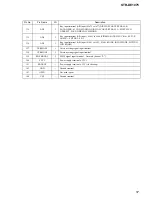
132
AD1
I
Key input terminal (A/D input) S1681 to 1685, S1702 to 1704 (AM, FM, FM MODE,
SHIFT, MEMORY, DISPLAY, ON SCREEN, DIMMER)
133
AD2
I
Key input terminal (A/D input) S1651 to 1658 (LEVEL, SURR, EQ, <, PRESET TUNING –
/+, /–)


