background image

Summary of Contents for STR-DE575 - Fm Stereo/fm-am Receiver

Page 1: ...SONY 4 233 598 12 i FM Sterno FM AM Receiver Operating Instructions STR DE675 STR DE575 STR K502 0 2001 Sony Corporation ...

Page 2: ... AN EXTENSION CORD RECEPTACLE OR OTHER OUTLET UNLESS THE BLADES CAN BE FULLY INSERTED TO PREVENT BLADE EXPOSURE For customers in the United States and Canada ENERGY STAR is a U S registered mark As an ENERGY STAR partner Sony Corporation has determined that this product meets the ENERGY STAR guidelines for energy efficiency Precautions On safety l Should any solid object or liquid fall into the ca...

Page 3: ... and the double D symbol 00 me trademarks of Dolby Labmatories Confidential unpublished Walks 0 1992 1997 Dolby Laboratories All rights eserued Manufnctured rrndef licensefvon Digital Theater Systems Inc US Pat No 5 451 942 5 956 674 5 974 380 58978 762 and other world wide patents issued and pending DTS and DTS Digital Surround are registered trademarks of Digital Theater Systems Inc Copyright 19...

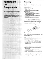
Page 4: ...n the remote no longer operates the receiver replace all batteries with new ones Notes l Do not leave the remote in an extremely hot or humid place l Do not use a new battery with an old one l Do not expose the remote sensor to direct sunlight or lighting apparatuses Doing so may cause a malfunction l If you don t use the remote for an extended period of time remove the batteries to avoid possible...

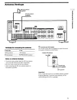
Page 5: ...AL terminal l To prevent noise pickup keep the AM loop antenna away from the receiver and other components l Be sure to fully extend the FM wire antenna l After connecting the FM wire antenna keep it as horizontal as possible Outdoor FM antenna Receiver r 7 Ground wire not supplied 4 To ground Important If you connect the receiver to an outdoor antenna ground it against lightning To prevent a gas ...

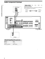
Page 6: ...eck Audio cords not supplied When connecting a cord be sure to match the color coded pins to the appropriate jacks on the components White 1 Red R White L Red R J Connect a To the CD player CD jacks MD deck or Tape deck MD TAPE jacks 6 ...

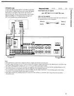
Page 7: ...D player DVD LD jacks TV monitor MONITOR VIDEO OUT jack STR DE675 only You can connect your TV s audio output jacks to the TV SAT AUDIO IN jacks on the receiver and apply sound effects to the audio from the TV In this case do not connect the TV s video output jack to the TV SAT VIDEO IN jack on the receiver If you are connecting a separate TV tuner or satellite tuner connect both the audio and vid...

Page 8: ...hite L audio Red R audio Note The optical and coaxial digital input jacks on the receiver are compatible with sampling frequencies of 32 kHz 44 1 kHz and 48kHz When making digital audio connections to a DVD playec connect to either the coaxial OR optical digital jacks and not both It is recommended to make digital audio connections to the coaxial jack Please note that you cannot connect an LD play...

Page 9: ... digital multi channel surround signal l To make a digital recording from your CD player connect the CD player s digital output directly to the digital input on your MD or tape deck Refer to the instructions supplied with your CD player and MD or tape deck for details l The DVD LD IN OPTICAL and COAXIAL jacks are compatible with 96 kHz 48 kHz 44 1 kHz and 32 kHz sampling frequencies The other OPTI...

Page 10: ...rs and a center speaker and a sub woofer Refer to the instruction manual supplied with your DVD player multi channel decoder etc for details on the multi channel input hookups DVD player Multichannel decoder etc Audio cords not supplied Two for the MULTI CH IN FRONT and SURROUND jacks White L Red R White L Red R Monaural audio cords not supplied Two for the MULTI CH IN CENTER and SUB WOOFER jacks ...

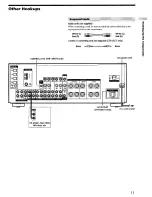
Page 11: ...the color coded pins to the appropriate jacks on the components Ii White L White L Red R Red R g Control Al connecting cord not supplied STR DE675 only Black P Black CONTROL Al n STR DE675 only I AC GUTLET STR DE675 only To a wall outlet CD player tape deck 11 ...

Page 12: ...er to the VIDEO IN jacks on the receiver l If you have an individual audio component except PHONO Use the audio cords to connect the LINE OUT jacks on the CD player tape deck or MD deck to the AUX AUDIO IN jack on the receiver so that you can listen to stereo sources in surround sound Before connecting the AC power cord of this receiver to a wall outlet l Connect the speaker system to the receiver...

Page 13: ...ofbuttcnsa d tontrol IQ g 9 Q SET UP button Pless to enter the setup mode when specifying speaker types and distances Cursor buttons I Use to select palametels after Gf pessing the SET UP button P Jog dial Use to adjust the setting of each parameter 13 ...

Page 14: ...ords about 2 13 inch 10 mm Be sure to match the speaker cord to the Front speakers 8 or 4 ohm SPEAKERS FRONT terminals appropriate terminal on the components to and Surround speakers 8 ohm SPEAKERS SURROUND terminals to If the cords are reversed the sound will be distorted and will lack bass Center speaker 8 ohm SPEAKERS CENTER terminals l If you use speakers with low maximum input rating Active s...

Page 15: ... test tone or a test tone is output from a speaker other than the one whose name is currently displayed on the receiver the speaker may be short circuited If this happens check the speaker connection again Set the IMPEDANCE SELECTOR for the front speakers as indicated in the table below Check the instruction manual supplied with your speakers if you re not sure of their impedance This information ...

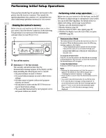
Page 16: ...your system You can set the following items For details on how to adjust each setting see the page in parentheses l Speaker size and placement page 17 l Speaker distance page 19 l Select the MULTI CH IN video signal page 45 l Whether the display turns off or not when you press DIMMER page 45 Demonstration Mode The demonstration will activate the first time you turn on the power When the demonstrat...

Page 17: ...MICRO SF if you re using Micro Satellite speakers If you choose NORM SF you can adjust the speaker size and the sub woofer selection as mentioned below However if you choose MICRO SI the speaker size and the sub woofer selection has been configurated as follows Speakers Settings Front SMALL Center SMALL Surround SMALL Woofer YES You cannot change the configuration if you choose MICRO Sl For STR K5...

Page 18: ... redirection circuitry and output the surround channel bass frequencies from the sub woofer or other LARGE speakers l If you do not connect surround speakers select NO 3 p cJ correspond to the following Dolby Pro logic modes NORMAL PHANTOM 3 3 STEREO About speaker sizes LARGE and SMALL Internally the LARGE and SMALL settings for each speaker determine whether or not the internal sound processor wi...

Page 19: ...eeds in forming a cohesive space between the surround sound from the surround speakers and the sound from the front speakers If you are not sure which sounds best select PL BEHD and then use the speaker distance parameter and speaker level adjustments to obtain proper balance n Sub woofer selection Initial setting S W YES l If you connect a sub woofer select SW YES l If you do not connect a sub wo...

Page 20: ...e Adjusting these parameters while listening to the sound often results in much better surround sound Give it a try Use the remote while seated in your listening position to adjust the volume of each speaker Note This receiver incorporates a new test tone with a frequency centered at 800 Hz for easier speaker volume adjustment Press I to turn on the receiver Press TEST TONE on the supplied remote ...

Page 21: ...nd the surround speakers about 1 2 dB is likely to produce better results In other words in order to create a more cohesive soundstage with balanced dialog we recommend that you make some adjustments while playing your software Changes of only 1 dB can make a huge difference in the character of the soundstage After connecting all of your components to the receiver do the following to verify that t...

Page 22: ...to verify that sound is output from the headphones see H SPEAKERS button and PHONES jack on page 25 If only one channel is output from the headphones the component may not be connected to the receiver correctly Check that all the cords are fully inserted into the jacks on both the receiver and the component If both channels are output from the headphones the front speaker may not be connected to t...

Page 23: ...z display window as follows f c I fin index name of the compotwnt or the preset station FUNCTION button indication or frequency Sound field applied to the program source 8 b a g a q DIMMER button Press repeatedly to adjust the brightness of the display When you want to turn off the display set in the DIM RANGE parameter in the SET UP menu page 45 23 ...

Page 24: ...tton Selects the AM band q MULTI CHANNEL DECODING indicator This indicator lights up when the unit is decoding signals recorded in a multi channel format q Use the CINEMA STUDIO EX buttons to enjoy the CINEMA STUDIO EX sound effects AIBIC buttons Press to activate the CINEMA STUDIO EX A B or C sound field page 29 q Use the SOUND FIELD buttons to enjoy surround sound For details see Enjoying Surrou...

Page 25: ... player turn on the TV and set the TV s video input to match the component you selected q MASTER VOLUME control After turning on the component you selected rotate to adjust the volume q MUTING button Press to mute the sound MUTING appears in the display when the sound is muted q EQUALIZER button p c Press to turn the equalizer on or off The EQ indicator in the display lights when the equalizer is ...

Page 26: ...en YOU select You can Speaker type Specify the type of speakers page 17 Speaker setup Specify the front center surround speaker sizes the surround speaker position and whether or not you are using a sub woofer Daze 17 When you select Speaker Distance You can Specify the front center and surround speaker distances page 19 MULTI CH IN video input Specify the video input to be used with the audio sig...

Page 27: ...ts commonly found in movie theaters The virtual sound modes contain compelling applications of the Sony Digital Cinema Sound digital signal processing technology They shift the sound away from the actual speaker locations to simulate the presence of several virtual speakers The music etc sound modes are designed for use with standard audio sources and TV broadcasts They add reverberation to the so...

Page 28: ...mply by selecting one of the pre programmed sound fields according to the program you want to listen to 1 Press MODE The current sound field is indicated in the display 2 Turn the jog dial or press the cursor buttons or to select the sound field you want See the table starting on page 29 for information on each sound field To turn the sound field off Press A F D or 2CH page 24 P The receiver memor...

Page 29: ...DIO EX C 2 Entertainment s BGM recording studio by using the 3D or classic films where music is featured in 5 m Press CINEMA STUDIO EX C sound imaging of VM DIMENS page 30 to create 5 sets the soundtrack button of virtual speakers surrounding the listener from a single r pair of actual surround speakers fj SC EXA SEMI CINEMA STUDIO EX A S C EXB SEMI CINEMA STUDIO EX B SC EXC SEMI CINEMA STUDIO EX ...

Page 30: ...on S HALL Reproduces the acoustics of a small rectangular concert SMALL HALL hall Ideal for musicals and opera L HALL LARGE HALL J Z Reproduces the acoustics of a large rectangular concert hall Reproduces the acoustics of a jazz club L HOUSE LIVE HOUSE Reproduces the acoustics of a 300 seat live house Great for rock or pop music GAME Obtains maximum audio impact from video game software Be sure to...

Page 31: ...t speakers only Standard two channel stereo sources completely bypass the sound field processing Multi channel surround formats are downmixed to two channels This allows you to play any source using only the front left and right speakers Notes l No sound is output from the sub woofer when the 2 CHANNEL mode is selected To listen to two channel stereo sources using the front left and right speakers...

Page 32: ...q D RANGE Lights up when dynamic range compression is active See page 36 to adjust the dynamic range compression q COAX Lights up when the source signal is a digital signal being input through the COAX terminal q OPT Lights up when the source signal is a digital signal being input through the OPT terminal q Play back channel indicators The letters light up to indicate the channels being played bac...

Page 33: ......

Page 34: ......

Page 35: ......

Page 36: ......

Page 37: ......

Page 38: ......

Page 39: ......

Page 40: ......

Page 41: ......

Page 42: ......

Page 43: ......

Page 44: ......

Page 45: ......

Page 46: ......

Page 47: ......

Page 48: ......

Page 49: ......

Page 50: ......

Page 51: ......

Page 52: ......

Page 53: ......

Page 54: ......

Page 55: ......

Page 56: ......

Page 57: ......

Page 58: ......

Page 59: ......

Page 60: ......

Page 61: ......

Page 62: ......

Page 63: ......

Page 64: ......

Page 65: ......

Reviews: