background image

46

E

Información adicional

Solución de problemas

Si experimenta cualquiera de las dificultades siguientes
cuando utilice el receptor, use esta guía de solución de
problemas para tratar de resolver el problema.  Si el
problema persiste, consulte a su proveedor Sony más
cercano.

La alimentación del televisor se desconecta al conectar
la del receptor con el telemando.

/

Cerciórese de que la alimentación del
televisor esté desconectada cuando conecte la
del receptor con el telemando.

Al seleccionar una fuente de programas en el menú
FUNCTION SELECT, la alimentación de tal fuente se
desconecta.

/

La alimentación de tal fuente fue conectada
con un telemando diferente.  La fuente de
programa tiene que haber sido conectada con
el receptor o manualmente.

La alimentación de algunos equipos no se desconecta al
hacer clic en la tecla ALL OFF.

/

La alimentación de tal equipo fue conectada
con un telemando diferente.  Desconecte
manualmente su alimentación.

No hay sonido, o solamente se oye sonido a un nivel muy
bajo.

/

Compruebe si los altavoces y los
componentes están conectados con seguridad.

/

  Cerciórese de que ha seleccionado el

componente correcto.

/

Cerciórese de que el interruptor SPEAKERS
esté en ON.

/

Si en el visualizador está indicándose
“MUTING”, haga clic en el icono 

.

/

Se ha activado el dispositivo de protección
del receptor debido a un cortocircuito.
(Parpadeará “PROTECTOR”.)  Desconecte la
alimentación del receptor, elimine el
cortocircuito, y vuelva a conectar la
alimentación.

El sonido de los altavoces izquierdo y derecho está
desequilibrado o invertido.

/

Compruebe si los altavoces y los
componentes están conectados correctamente
y con seguridad.

/

Ajuste el control BALANCE.

Se oye zumbido o ruido considerable.

/

Compruebe si los altavoces y los
componentes están conectados con seguridad.

/

Compruebe si los cables conectores están
alejados de un transformador o motor, y a 3
metros por lo menos de un televisor o una
lámpara fluorescente.

/

Aleje su televisor de los componentes de
audio.

/

Cerciórese de conectar un conductor de
puesta a tierra al terminal de tierra.

/

Las clavijas y las tomas están sucias.  Frótelas
con un paño ligeramente humedecido en
alcohol.

No se oye sonido a través del altavoz central.

/

Seleccione un campo acústico PRO LOGIC o
MOVIE (exepto película monoaural) (consulte
la página 30 y 31).

/

Seleccione el modo central apropiado
(consulte la página 32).

/

Ajuste apropiadamente el volumen de los
altavoces (consulte la página 32).

No es posible grabar.

/

Compruebe si los componentes están
correctamente conectados.

/

Seleccione el componente fuente del menú
FUNCTION SELECT o con las teclas de
función.

No hay sonido o solamente se oye sonido de nivel muy
bajo a través de los altavoces traseros.

/

Active la función de campo acústico.

/

Seleccione el modo central apropiado
(consulte la página 32).

/

Ajuste apropiadamente el volumen de los
altavoces (consulte la página 32).

/

Cerciórese de haber activado la función de
campo acústico.

No es posible sintonizar emisoras.

/

Compruebe si las antenas están conectadas
con seguridad.
Ajuste las antenas y, si es necesario, conecte
una antena exterior.

/

La intensidad de la señal de las emisoras es
débil (cuando utilice la sintonía automática).
Use la sintonía directa.

/

Cerciórese de ajustar correctamente el
intervalo de sintonía (cuando desee sintonizar
emisoras de AM con la sintonía automática)
(consulte las páginas 48).

/

No se han memorizado emisoras, o las
emisoras memorizadas se han borrado
(cuando sintonice con la exploración de
emisoras memorizadas).  Memorice las
emisoras (consulte la página 26).

Summary of Contents for STR-DE805G - Fm/am Stereo Receiver

Page 1: ...FM Stereo FM AM Receiver Operating Instructions Mode d emploi Manual de Instrucciones 1996 by Sony Corporation 3 856 142 31 1 STR DE905G STR DE805G EN F E C ...

Page 2: ...pose of safety and will fit into the wall outlet only one way If you are unable to insert the plug fully into the outlet contact your dealer AC power cord must be changed only at the qualified service shop On placement Do not install the appliance in a confined space such as a bookcase or built in cabinet Place the receiver in a location with adequate ventilation to prevent heat buildup and prolon...

Page 3: ... play 39 Settings and Adjustments Remote Operation of Audio Sources Without the TV illuminated control flasher 40 Playing Sources Automatically auto play 41 Starting a Source Automatically at Power On auto start 41 Adjusting the Sensitivity of the Remote 42 Selecting the Display Parameters 42 Adjusting the Position of the On Screen Display 43 Additional Information Front Panel Descriptions 44 Rear...

Page 4: ...e the various connected audio video components Use the remote to move the pointer hand shaped icon on the on screen display and select functions STR DE905G STR DE805G This unit s on screen display lets you control audio video components as well as any other device that can be controlled by an infrared remote control such as lighting fixtures For details on how the receiver controls other equipment...

Page 5: ...eceiver also incorporates a Dolby Pro Logic decoder so you can enjoy programs recorded in Dolby Surround with a surround effect similar to a movie theater CD Changer Control Connecting a Sony CD changer equipped with a Control A1 terminal allows you to access and display the disc information stored in the CD changer in alphabetical order numerical order or by group name You can also select the dis...

Page 6: ...d IR repeater transmits the corresponding IR control code to the respective program source 3 above If the screen flickers or the pointer does not move The RF signal from the remote is being obstructed and is not reaching the RC antenna 1 above Reposition the RC antenna or bring the remote commander closer to the RC antenna If the program source fails to respond or is slow to respond The IR control...

Page 7: ...move when you press the direction control button The IR code from the remote is not fully reaching the infrared receptor on the receiver 1 above Make sure there are no obstacles between the remote and the receiver If the program source fails to respond or is slow to respond The IR control code from the IR repeater is not fully reaching the infrared receptor on the program source Connect the extra ...

Page 8: ...d To learn the locations and names of each jack see Rear Panel Descriptions on page 45 Before you get started Turn off the power to all components before making any connections Do not connect the AC power cords until all of the connections are completed Be sure to make connections firmly to avoid hum and noise When connecting an audio video cable be sure to match the color coded pins to the approp...

Page 9: ...onnect the supplied extra infrared IR repeater to the receiver The repeater emits infrared signals corresponding to those emitted by the remote controls supplied with the respective components Connected this repeater to obtain additional coverage if you experience difficulty controlling a certain component using the receiver s on screen display OSD control functions or your installation prevents t...

Page 10: ...okups starting on page 11 Audio Component Hookups Overview This section describes how to connect your audio components to the receiver If you want to use the receiver as an amplifier complete these connections For specific locations of the jacks see the illustration below What cords will I need Audio cords not supplied 1 for each CD player and turntable 2 for each tape deck DAT deck or MD deck FM ...

Page 11: ...t terminals VIDEO 1 VIDEO 2 or LD Tape deck Receiver Receiver Turntable Speaker System Hookups Overview This section describes how to connect your speakers to the receiver Although front left and right speakers are required center and rear speakers are optional Adding center and rear speakers will enhance the surround effects Connecting an active woofer will increase bass response For specific loc...

Page 12: ... What cables will I need Audio video cable not supplied 1 for each TV or LD player 2 for each VCR Video cable not supplied 1 for a TV monitor Hookups The arrow ç indicates signal flow Monitor If you are using your TV as a monitor do not connect anything to the TV DBS IN jacks unless you have a Sony TV with TV OUT jacks see page 25 for details TV tuner or DBS Digital Broadcasting Satellites receive...

Page 13: ... SWITCHED AC OUTLET s on the receiver the receiver can supply power to the connected components so you can turn on off whole system when you turn on off the receiver Caution Make sure that the power consumption of the component s connected to the receiver s AC outlet s does not exceed the wattage indicated on the rear panel Do not connect high wattage electrical home appliances such as electric ir...

Page 14: ...than three months depending on how much you handle the remote When the batteries become weak LOW will appear on the display during the initial on screen displays but possibly not at the deeper menu levels When EMPTY appears the batteries are almost completely drained and will soon need to be replaced Inserting Batteries Into the Remote STR DE805G 1 Open the cover on the bottom of the remote 2 Inse...

Page 15: ...t of yellow switches as shown below Use the tip of a pen or some other pointed object to flip up the appropriate switches for each digit of the security number refer to the chart on the following page Note that all switches are down for zero and all switches are up for fifteen 5 Reinsert the batteries and place the remote on a flat surface for about 10 seconds How to Use the Remote STR DE905G The ...

Page 16: ...ter should behave normally the next time you use the remote If your hand is very dry the on screen display may not appear when you touch the click button In this case press the click button Caution Since the remote contains delicate circuitry and parts do not subject it to sudden changes in temperatures or to shock How to Use the Remote STR DE805G The supplied remote lets you perform almost all of...

Page 17: ...2 Click FUNCTION in the main menu 3 Click TV SET 4 Click OTHER TV or click Sony TV for a Sony TV Australian Malaysian and Singaporean models Other models If you connected the receiver to the VIDEO 2 or 3 jacks on your TV or monitor Click VIDEO 1 2 3 to specify the correct video input If you are using a wide TV Click WIDE to specify WIDE This operation is unnecessary for customers in Australia Mala...

Page 18: ...below to erase the VIDEO 1 code To exit to the main menu Click EXIT To return to a previous menu Click RETURN To erase TV IR codes Click CODE CLEAR To erase a specific IR code 1 Click SINGLE IR CODE CLEAR 2 Click the button you want to clear Are you sure appears for confirmation 3 Click YES to erase the code CODE CLEAR appears in the display To stop before erasing a code click NO To erase another ...

Page 19: ...AND CODE selector switch to VTR 3 If your CD changer has a COMMAND MODE selector switch for CD 1 CD 2 or CD 3 normally it should be set to CD 1 However if your CD changer has VIDEO OUT terminals set the command mode to CD 2 or CD 3 CD 3 should only be used when making CONTROL A1 connections Registering non Sony audio video equipment If you connect audio or video equipment made by another manufactu...

Page 20: ...t to prevent accidental operation during the programing procedure click START then go to step 6 If the equipment is a video deck or laser disc player 1 Click START A list of other manufacturers appears 2 Click the manufacturer of the respective equipment and the IR codes for that program source are registered automatically If the manufacturer is not listed cover the IR sensor on the equipment to p...

Page 21: ...ck YES to erase the code CODE CLEAR appears in the display To stop before erasing a code click NO To erase another code repeat steps 2 and 3 To erase all the IR codes for the current component e g OTHER CD 1 Click OTHER CD CODE CLEAR Are you sure appears for confirmation 2 Click YES to erase the codes CODE CLEAR appears in the display To stop before erasing the codes click NO To erase all the IR c...

Page 22: ...for approximately two weeks If they disappear ALL CLEAR will appear on the TV screen the next time you turn on the receiver Do not operate the remote supplied with the STR DE805G when PUSH YOUR COMMANDER appears on the TV screen in step 6 Programing IR codes from the supplied remote may cause the STR DE805G to malfunction Programming Other Infrared IR Codes USER IR setting Use the USER IR CODE SET...

Page 23: ...he button you want to clear Are you sure appears for confirmation 3 Click YES to erase the code CODE CLEAR appears in the display To stop before erasing a code click NO To erase another code repeat steps 2 and 3 To erase all the user IR codes 1 Click USER IR CODE CLEAR Are you sure appears for confirmation 2 Click YES to erase the codes CODE CLEAR appears in the display To stop before erasing the ...

Page 24: ... ALL OFF If you have components that turn on only when you press the play button they will not turn off you click ALL OFF when the AUTO PLAY function see page 41 is off In this case click then on the play button Selecting a Component To listen to or watch a connected component go to the function select menu and click on the program source you desire Before you begin make sure you have Connected th...

Page 25: ...splay the WIDE TV DISPLAY control panel then click the button for the display mode you desire This operation is only possible when TV SIZE in the TV MONITOR SET menu is set to WIDE see page 17 Notes The AUTO PLAY function is set at the factory to start playing the component immediately after it is selected To turn AUTO PLAY off see page 41 Components of the same type will be controlled simultaneou...

Page 26: ...m the on screen display You can store up to 30 FM or AM stations and recall them later with a simple click To assign names to the preset stations see page 35 Before you begin make sure you have Connected the RC antenna securely and correctly as indicated on page 9 STR DE905G only Connected an FM AM antennas to the receiver as indicated on page 10 1 Click FUNCTION in the main menu 2 Click TUNER 3 C...

Page 27: ...FM simulcast TV programs Make sure that you tune in the simulcast program on both the TV or VCR and the receiver Tuning preset stations preset tuning 1 Click FUNCTION in the main menu 2 Click TUNER 3 Click LIST 4 Click A B C repeatedly to display the station you want 5 Click the button 0 to 9 for the respective station To recall preset stations from the SUB menu 1 Click SUB 2 Click A B C repeatedl...

Page 28: ...urce and RECORDER for the program destination The green arrow indicates the source component When recording the green arrow should be next to PLAYER Clicking a RECORDER control while recording cuts off the program source PLAYER 6 Insert a blank tape into the recording component or VCR etc and adjust the recording level if necessary 7 Click the REC to start recording then click the PLAYER control R...

Page 29: ...ck 1 Click EXIT 2 Click FUNCTION in the main menu 3 Click TAPE To stop recording Click on p of the recording unit To return to the main menu Click EXIT Notes There is no sound output from the recording component even though all the buttons on the recording unit s control panel are operational If you click RECORDER during recording the source being recorded will be cut off If you leave the REC EDIT...

Page 30: ...icated on the package To create your own sound field See Customizing Sound Fields on page 33 to adjust the tone and surround parameters For additional information regarding surround sound See the Glossary on pages 49 and 50 Using Surround Sound Using Pre programmed Sound Fields You can take advantage of surround sound simply by selecting one of the pre programmed sound fields according to the prog...

Page 31: ...EATER Add the acoustic reflections of theater to decoded Dolby Surround signals LARGE THEATER MONO MOVIE Create a theater like environment from movies with monaural soundtracks MUSIC 1 SMALL HALL Reproduce the acoustics of a rectangular concert hall Ideal for soft acoustic sounds LARGE HALL MUSIC 2 KARAOKE Reduce the vocal tracks of stereo music sources ACOUSTIC Reproduce normal 2 channel stereo w...

Page 32: ... PHANTOM 3 CHANNEL LOGIC NORMAL and WIDE Each mode is designed for a different speaker configuration Select the mode that best suits your speaker system configuration 1 Click SOUND in the main menu 2 Click PRO LOGIC to select the pro logic sound field 3 Click SUR The Dolby Pro Logic SUR EDIT screen appears To select the pro logic sound field SOUND FIELD SELECT EXIT SOUND FIELD BASS BOOST PRO LOGIC...

Page 33: ... To reset the current sound field to the original factory settings Click STD Adjusting the tone You can adjust the tone of the speakers Follow the procedure described in Adjusting the tone below Customizing the Sound Fields Each sound field is composed of an equalizer bass midrange or treble and surround sound parameters variables of sound that create the sound image You can customize the sound fi...

Page 34: ...und on page 32 1 Start playing a program source then click SOUND in the main menu 2 Click the genre of sound field you want to reset The previously selected mode turns on automatically 3 Click MODE repeatedly to select the mode you want to adjust 4 Click SUR The SUR EDIT menu appears To adjust the speaker levels Click LEVEL then click or to adjust the speakers to the levels you prefer To adjust th...

Page 35: ...ng each character in order The name is stored automatically To enter a space Click the space bar To switch between upper and lower case letters Click CAPS If you make a mistake Click or to move the cursor to the character to be changed then click the correct character or click the space bar to erase the character To go back to the previous menu Click RETURN To exit to the main menu Click EXIT Addi...

Page 36: ...ta appears in the CD INDEX SETTING menu Notes The DATA LOAD button will not appear if the CD changer is not registered as a Sony CONTROL A1 CD in the IR CODE SETTING menu see page 20 or if the CD changer is not turned on The DATA LOAD procedure will not work if the CD change is not turned on or if the CTRL A1 connection is incomplete see page 11 If the following characters have been recorded in th...

Page 37: ...N in the main menu The FUNCTION SELECT menu appears 2 Click INDEX The INDEX SETTING screen appears 3 Click the LIST CD button 4 Click SELECT then click the disc you want to assign to a new group If the disc you want is not displayed Click the or icon to display the disc 5 Click the names of the groups you want to assign the CD to For example to assign the CD to both GROUP 1 and GROUP 4 click both ...

Page 38: ...yback starts automatically Notes Depending on the type of CD changer connected 3 or 5 disc changer etc you may not be able to select the CD even by clicking the disc name In this case select the CD from the normal CD control panel If the CD changer is made by another manufacturer and the sequence of operations required to start playback is other than 1 pressing a numeric button followed by 2 press...

Page 39: ...turn off all the components Click or repeatedly to display ALL OFF Note If the macro was selected for automatic execution at startup with the AUTO START function see page 41 ALL OFF cannot be selected in that macro 6 Click on the IR code you desire The name of the IR code appears in the highlighted macro step number and the next macro step number is highlighted 7 Repeat steps 5 and 6 to enter up t...

Page 40: ...selected program source appear in the display according to the movement of the remote The indicator corresponding to the operation button on the front panel also lights up The operations available for each program source are shown below Program source Operations DAT MD p CD p TUNER PRESET PRESET PHONO No display TAPE 0 p All sources INPUT SELECT ALL OFF TV ON VOLUME VOLUME MUTE 7 Click the remote ...

Page 41: ... lets you set the receiver to start playing a specific program source immediately whenever you turn on the receiver 1 Click FUNCTION in the main menu The FUNCTION SELECT menu appears 2 Click AUTO The AUTO START SETTING screen appears 3 Click the component you want to start playing automatically when the receiver is turned on Only one program source can be selected To automatically start the compon...

Page 42: ...the IR OUTPUT setting when you use the IR repeater 1 Click FUNCTION in the main menu The FUNCTION SELECT menu appears 2 Click SET UP 3 Click AUTO OSD ERASE ON or OFF POINTER ONLY SET or DEMO START to select the display mode as necessary If necessary click IR OUTPUT ON or OFF AUTO OSD ERASE This display mode is useful during laser disc operations since it allows you to see chapter numbers that othe...

Page 43: ...r on the front panel When the IR OUTPUT is set to OFF IR OFF appears in the main menu Normally IR OUTPUT should be set to ON To return to the main menu Click EXIT To go to the previous menu Click RETURN Adjusting the Position of the On Screen Display The graphic position function GRAPHIC POSITION lets you make fine adjustments to the overall position of the on screen display control panel 1 Click ...

Page 44: ...Disc button Selects the lase disc player connected to the LD jacks VIDEO 1 3 buttons Selects the video components connected to the VIDEO 1 3 jacks TAPE MONITOR button For monitoring audio program sources during recording PHONES jack For connecting stereo headphones ª SPEAKERS selector For turning the speakers OFF or ON 7 SOUND FIELD button Turns the sound field on and off 8 VIDEO 3 INPUT jacks For...

Page 45: ...AUDIO OUT 0 FRONT SPEAKERS IMPEDANCE SELECTOR See page 12 VOLTAGE SELECTOR certain models only AC power cord SWITCHED AC OUTLETs Outlet shape and position varies according to destination CENTER SPEAKER REAR SPEAKERS TAPE DAT MD ª CD º PHONO ANTENNA AM FM y SIGNAL GND terminal Rear Panel Descriptions 1 2 3 4 6 5 7 8 9 0 ª º ...

Page 46: ...ntrol Severe hum or noise is heard Check that the speakers and components are connected securely Check that the connecting cords are away from a transformer or motor and at least 3 meters away from a TV set or fluorescent light Place your TV away from the audio components Make sure you connect a ground wire to the antenna ground terminal The plugs and jacks are dirty Wipe them with a cloth slightl...

Page 47: ...not function Replace both batteries in the remote with new ones if they are weak Connect the RC antenna to the RC ANT jack on the rear of the receiver STR DE905G only see page 9 Remove the obstacles in the path of the remote and the receiver STR DE805G only Remove the obstacles in the path of the remote and the RC antenna STR DE905G only Make sure both the remote and receiver are set to the same s...

Page 48: ... amplifier section Pure complimentary SEPP Australian Singaporean and Malaysian models 240 V AC 50 60 Hz Other models 120 220 240 V AC 50 60 Hz Singaporean and Malaysian models 275 W Other models 270 W Australian and Singaporean models 1 switched 100 W Other models 1 switched 120 W 430 x 160 x 365 mm 10 0 kg FM wire antenna 1 AM loop antenna 1 Remote commander remote 1 Size AA R6 batteries 2 RC an...

Page 49: ...osition Dolby Pro Logic Surround Decoding system of Dolby Surround sound standardized in TV programs and movies Compared with the former Dolby Surround system Dolby Pro Logic Surround improves sound image by using four separate channels off screen audio effects on screen dialog left to right panning and music These channels manipulate the sound to be heard and enhance the action as it happens on t...

Page 50: ...C mode 32 49 WIDE mode 32 49 CD changer operation 37 Connecting See Hookups Customizing sound fields 33 D Delay time 33 49 Dolby Pro Logic Surround 49 getting the most out of 32 Dolby Surround sound 32 49 center mode 32 49 Dubbing See Recording E Editing See Recording Effect level 34 49 F Front panel 44 G Grouping CDs 37 H Hookups AC power cord 13 AM FM antennas 10 audio components 10 IR repeater ...

Page 51: ...ns 26 Searching for a CD 38 Selecting a program source 24 Sleep timer 29 Sound field customizing 33 pre programmed 30 Speakers connection 11 impedance 12 placement 11 Station index 35 Storing radio stations See Presetting Surround sound 30 49 T Test tone 32 50 3 CH LOGIC mode 32 49 Troubleshooting 46 Tuning See Receiving broadcasts TV VCR hookups 12 U V W X Y Z Unpacking 8 ...

Page 52: ...vez l insérer que dans un sens Si vous avez du mal à enfoncer complètement la fiche dans la prise contactez votre revendeur Si le cordon d alimentation secteur doit être remplacé adressez vous à un technicien qualifié uniquement Installation N installez pas l appareil dans un espace confiné comme dans une bibliothèque ou un meuble encastré Installez l ampli tuner dans un endroit bien ventilé pour ...

Page 53: ...équentielle de plusieurs appareils lecture macro 39 Réglages et ajustements Commande à distance de sources audio sans le téléviseur Commande avec témoins 40 Lecture automatique d une source AUTO PLAY 41 Démarrage automatique d une source à la mise sous tension AUTO START 41 Réglage de la sensibilité de la télécommande 42 Sélection des paramètres d affichage 42 Réglage de la position de l affichage...

Page 54: ...ermet de piloter divers appareils audio vidéo Utilisez la télécommande pour déplacer le pointeur en forme de main sur l écran et sélectionner des fonctions STR DE905G STR DE805G L affichage sur écran vous permet de contrôler des appareils audio vidéo ainsi que tout autre appareil pouvant être contrôlé par une télécommande infrarouge comme des suspensions d éclairage Pour les détails sur le contrôl...

Page 55: ...deur Dolby Pro Logic qui vous permet d écouter des programmes enregistrés en surround Dolby avec des effets surround tels qu au cinéma Contrôle de changeur CD Le raccordement d un changeur CD Sony avec système Control A1 vous permet d accéder et d afficher les informations concernant les disques stockées dans le changeur CD dans un ordre alphabétique ou numérique ou par nom de groupe Vous pouvez a...

Page 56: ...la touche de la télécommande le répéteur infrarouge IR transmet le code de commande IR correspondant à la source de programme appropriée 3 ci dessus Si l image vacille sur l écran ou que le pointeur ne bouge pas Le signal RF de télécommande est gêné par un obstacle et ne peut pas atteindre l antenne RC 1 ci dessus Réorientez l antenne RC ou approchez la télécommande de l antenne RC Si la source de...

Page 57: ...ichage n apparaît pas ou que le pointeur ne bouge pas quand vous appuyez sur la touche directionnelle Le code IR de la télécommande n atteint pas complètement le récepteur infrarouge de l ampli tuner 1 ci dessus Enlevez tout objet qui pourrait faire obstacle entre la télécommande et l ampli tuner Si la source de programme ne réagit pas ou réagit lentement Le code de commande IR du répéteur infraro...

Page 58: ...e du panneau arrière page 45 Téléviseur Magnétoscope Lecteur LD Raccordement d un téléviseur magnétoscope 12 Enceinte arrière droite Raccordement de l antenne RC STR DE905G seulement 9 Antennes FM AM Raccordement d antennes 10 Enceinte avant gauche Enceinte arrière gauche Lecteur CD Platine à cassette Platine DAT MD Tourne disque Raccordement de composants audio 10 Enceinte centrale Caisson de gra...

Page 59: ...accorder le répéteur infrarouge IF d appoint fourni avec l ampli tuner Le répéteur émet des signaux infrarouges correspondant à ceux émis par la télécommande fournie avec les appareils respectifs Raccordez ce répéteur pour augmenter la portée des rayons infrarouges si vous avez des difficultés à contrôler un appareil particulier quand vous utilisez les commandes de l ampli tuner affichées sur écra...

Page 60: ...cordement d enceintes page 11 Raccordement de composants audio Aperçu Ce paragraphe explique comment raccorder des composants audio à l ampli tuner Si vous souhaitez utiliser l ampli tuner comme amplificateur effectuez ces connexions L illustration ci dessous indique l emplacement des prises De quels cordons avez vous besoin Vous avez besoin de cordons audio non fournis 1 pour le lecteur CD ou le ...

Page 61: ... ou LD Raccordement d enceintes Aperçu Ce paragraphe explique comment raccorder des enceintes à l ampli tuner Vous devez raccorder des enceintes avant gauche et droite cependant vous pouvez choisir de raccorder ou non des enceintes centrale et arrière Raccordez des enceintes centrale et arrière pour accentuer l effet surround Raccordez un caisson de grave amplifié pour accentuer la réponse dans le...

Page 62: ...lacement des prises De quels cordons avez vous besoin Vous avez besoin de cordons audio vidéo non fournis 1 pour le téléviseur ou lecteur LD et 2 pour chaque magnétoscope Vous avez besoin également d un cordon vidéo non fourni 1 pour un moniteur TV Raccordement La flèche ç indique le sens du signal Moniteur Si vous utilisez le téléviseur comme moniteur ne branchez rien sur les prises TV DBS IN à m...

Page 63: ...prises SWITCHED AC OULET de l ampli tuner ils sont alimentés par l ampli tuner Ainsi tous les composants se mettent sous hors tension en même temps que l ampli tuner Précaution Vérifiez que la consommation électrique des composants raccordés aux prises secteur de l ampli tuner ne dépasse pas le nombre de watts indiqué sur le panneau arrière Ne raccordez pas d appareils électriques à consommation é...

Page 64: ...ins de trois mois selon la façon dont vous utilisez la télécommande Quand les piles sont faibles l indication LOW apparaît sur les affichages initiaux elle n apparaît pas toujours sur d autres menus Quand EMPTY apparaît les piles sont pratiquement épuisées et doivent être remplacées Mise en place des piles dans la télécommande STR DE805G 1 Ouvrez le couvercle sur la base de la télécommande 2 Insér...

Page 65: ...crayon ou un autre objet pointu relevez les commutateurs en fonction du code de sécurité choisi voir le tableau suivant sur cette page Notez que pour zéro tous les commutateurs sont abaissés et que pour quinze ils sont tous relevés 5 Remettez les piles en place et posez la télécommande sur une surface plane pendant environ 10 secondes Utilisation de la télécommande STR DE905G La télécommande fourn...

Page 66: ...erez la télécommande Si votre main est trop sèche l affichage sur écran risque de ne pas apparaître quand vous touchez la touche clic Dans ce cas appuyez dessus Précaution Etant donné que la télécommande renferme un circuit et des pièces fragiles ne l exposez pas à des changements de température brusques ni à des chocs Utilisation de la télécommande STR DE805G La télécommande fournie vous permet d...

Page 67: ...ez l ampli tuner et le téléviseur sous tension Vérifiez que le sélecteur d entrée du téléviseur est réglé sur l entrée vidéo 2 Cliquez sur FUNCTION dans le menu principal 3 Cliquez sur TV SET 4 Cliquez sur OTHER TV ou cliquez sur Sony TV pour un téléviseur Sony Modèles pour l Australie la Malaisie et Singapour EXIT TV MONITOR SET GRAPHIC POSITION RETURN TV IR SET Sony TV OTHER TV 1 VIDEO 3 2 TV IN...

Page 68: ...mer tous les codes IR du téléviseur 1 Cliquez sur TV IR CODE CLEAR Are you sure apparaît 2 Cliquez sur YES pour supprimer les codes CODE CLEAR apparaît à l écran Pour vous arrêter avant de supprimer les codes cliquez sur NO Pour supprimer tous les codes IR 1 Cliquez sur ALL IR CODE CLEAR Are you sure apparaît 2 Cliquez sur YES pour supprimer les codes CODE CLEAR apparaît à l écran Pour vous arrête...

Page 69: ...Si vous remplacez un appareil audio ou vidéo d une autre marque par un appareil Sony Remarques Si votre magnétoscope a un sélecteur COMMAND CODE pour VTR 1 VTR 2 ou VTR3 réglez le sélecteur sur la position appropriée Si votre magnétoscope a un tuner StarSight vous devez régler le sélecteur COMMAND CODE sur VTR 3 Si le changeur CD a un sélecteur COMMAND MODE pour CD 1 CD 2 ou CD 3 veillez à choisir...

Page 70: ... fabricant n est pas indiqué sur la liste recouvrez le détecteur IR de l appareil pour éviter toute opération accidentelle pendant la programmation puis cliquez sur OTHER et passez à l étape 6 3 Cliquez sur TEST Si la source de programme sélectionnée s allume c est que les codes IR ont bien été enregistrés et que la programmation est terminée Si la source de programme ne s allume pas cliquez sur l...

Page 71: ...er le menu principal Cliquez sur EXIT Pour revenir au menu principal Cliquez sur RETURN Pour supprimer des codes IR Cliquez sur CODE CLEAR Pour supprimer un code IR donné 1 Cliquez sur SINGLE IR CODE CLEAR 2 Cliquez sur la touche dont vous voulez supprimer le code Are you sure apparaît 3 Cliquez sur YES pour supprimer les codes CODE CLEAR apparaît à l écran Pour vous arrêter avant de supprimer les...

Page 72: ...us tension de l ampli tuner N utilisez pas la télécommande fournie avec le STR DE805G quand PUSH YOUR COMMANDER apparaît à l écran de télévision à l étape 6 La programmation de codes IR à partir de la télécommande fournie peut perturber le fonctionnement du STR DE805G Programmation d autres codes infrarouges USER IR CODE SETTING Utilisez le menu USER IR CODE SETTING pour programmer des codes IR qu...

Page 73: ... sur la touche correspondant au code que vous voulez supprimer Are you sure apparaît 3 Cliquez sur YES pour supprimer le code CODE CLEAR apparaît à l écran Pour vous arrêter avant de supprimer le code cliquez sur NO Pour supprimer d autres codes répétez les étapes 2 et 3 Pour supprimer tous les codes IR utilisateur 1 Cliquez sur USER IR CODE CLEAR Are you sure apparaît 2 Cliquez sur YES pour suppr...

Page 74: ...s Cliquez sur ALL OFF Si vous avez un appareil qui ne s éteint que lorsque vous appuyez sur la touche de lecture il ne s éteindra pas quand vous cliquez sur ALL OFF et que la fonction AUTO PLAY voir page 41 est hors service Dans ce cas cliquez sur puis sur la touche de lecture Sélection d un appareil Pour utiliser un des appareils raccordés sélectionnez le menu de fonction et cliquez sur la source...

Page 75: ...neau de commande WIDE TV DISPLAY puis cliquez sur la touche pour choisir le mode souhaité Cette opération est seulement possible quand TV SIZE dans le menu TV MONITOR SET est réglé sur WIDE voir page 17 Remarque La fonction AUTO PLAY a été réglée en usine pour que la lecture commence dès que vous sélectionnez un appareil Pour mettre AUTO PLAY hors service voir page 41 Les appareils de même type so...

Page 76: ...ur écran Vous pouvez prérégler jusqu à 30 stations FM ou AM pour pouvoir les accorder ensuite par un simple clic Pour attribuer un nom aux stations préréglées voir page 35 Avant de commencer vérifiez les points suivants L antenne RC a été raccordée correctement comme indiqué à la page 9 STR DE905G seulement Les antennes FM AM ont été raccordées à l ampli tuner comme indiqué à la page 10 1 Cliquez ...

Page 77: ...télévision en simulcast FM Assurez vous que le programme simulcast est accordé sur le téléviseur ou magnétoscope et sur l ampli tuner Pour accorder une station préréglée accord de préréglage 1 Cliquez sur FUNCTION dans le menu principal 2 Cliquez sur TUNER 3 Cliquez sur LIST 4 Cliquez de façon répétée sur A B C pour afficher la station souhaitée 5 Cliquez sur la touche 0 à 9 correspondant à la sta...

Page 78: ...paraissent à l écran de télévision PLAYER pour la source RECORDER pour l enregistreur La flèche verte indique l appareil source Pendant l enregistrement la flèche verte doit indiquer PLAYER Si vous cliquez sur une commande RECORDER pendant l enregistrement la source de programme sera coupée PLAYER 6 Insérez une cassette vierge dans l enregistreur ou magnétoscope etc et ajustez le niveau d enregist...

Page 79: ... étapes 1 à 7 de Enregistrement d appareils audio vidéo d une autre marque pages 19 à 22 pour un appareil Sony ou un appareil d une autre marque Le son fourni aux prises TAPE sur le panneau arrière ne peut pas être enregistré Si vous enregistrez sur une platine DAT ou MD raccordée aux prises DAT MD REC OUT les réglages du son 2 Cliquez sur SLEEP FUNCTION SELECT VIDEO 1 DAT MD CD VIDEO 2 TUNER VIDE...

Page 80: ...s indiqué sur l emballage Pour créer vos propres champs sonores Reportez vous à Personnalisation d un champ sonore à la page 33 pour ajuster les paramètres du timbre et du surround Pour d autres informations à propos du son surround Consultez le Glossaire aux pages 49 et 50 Utilisation du son surround SOUND FIELD SELECT SOUND FIELD BASS BOOST PRO LOGIC MOVIE MUSIC 1 MUSIC 2 SPORTS GAME VOL EXIT SO...

Page 81: ...surround Dolby sont décodés MOVIE SMALL THEATER Ajouter les réflexions typiques d un cinéma aux signaux surround Dolby décodés LARGE THEATER MONO MOVIE Simuler l ambiance d un cinéma pour les films en monophonie MUSIC 1 SMALL HALL Reproduire l acoustique d une salle de concert rectangulaire Idéal pour les sons doux LARGE HALL MUSIC 2 KARAOKE Réduire les voix de sources musicales stéréo ACOUSTIC Re...

Page 82: ...des enceintes Si toutes vos enceintes ont la même puissance vous n avez pas besoin de régler le volume des enceintes En utilisant la télécommande ajustez le niveau du volume à partir de votre position d écoute 1 Cliquez sur TEST La tonalité est émise tour à tour par chaque enceinte L enceinte qui émet la tonalité d essai est indiquée en rouge à l écran de télévision SOUND FIELD SELECT EXIT SOUND F...

Page 83: ...sine du champ sonore actuel Cliquez sur STD Réglage du timbre Vous pouvez ajuster le timbre des enceintes Procédez comme indiqué dans Réglage du timbre ci dessous Personnalisation d un champ sonore Chaque champ surround peut être ajusté avec l égaliseur grave médium aigu ou les paramètres du son surround variables du son qui créent une image sonore précise Vous pouvez personnaliser les champs sono...

Page 84: ...Commencez la lecture d une source de programme puis cliquez sur SOUND dans le menu principal 2 Cliquez sur le type de champ sonore que vous voulez régler Le mode précédemment sélectionné est automatiquement en service 3 Cliquez de façon répétée sur MODE pour sélectionner le mode que vous voulez ajuster 4 Cliquez sur SUR Le menu SUR EDIT apparaît Pour ajuster le niveau des enceintes Cliquez sur LEV...

Page 85: ...chaque caractère dans l ordre Le nom est automatiquement mémorisé Pour insérer un espace Cliquez sur la barre d espacement Pour alterner entre majuscules et minuscules Cliquez sur CAPS En cas d erreur Cliquez sur ou pour amener le curseur sur le caractère à remplacer puis cliquez sur un autre caractère ou sur la barre d espacement pour supprimer le caractère Pour revenir au menu précédent Cliquez ...

Page 86: ...utes sur le menu CD INDEX SETTING Remarques La touche DATA LOAD n apparaît pas si le changeur CD n est pas enregistré sous Sony CONTROL A1 CD dans le menu IR CODE SETTING voir page 20 ou si le changeur n est pas sous tension Le téléchargement des données ne fonctionne pas si le changeur CD n est pas sous tension ou si la liaison CTRL A1 n a pas été effectuée voir page 11 Si les caractères suivants...

Page 87: ... former un seul groupe 1 Cliquez sur FUNCTION dans le menu principal Le menu FUNCTION SELECT apparaît 2 Cliquez sur INDEX L écran INDEX SETTING apparaît 3 Cliquez sur la touche LIST CD 4 Cliquez sur SELECT puis sur le disque que vous voulez classer dans un groupe Si le disque souhaité n est pas affiché Cliquez sur le symbole ou pour afficher le disque 5 Cliquez sur le nom de tous les groupes dans ...

Page 88: ... disque La lecture commence automatiquement Remarques Selon le type de changeur CD raccordé changeur 3 ou 5 disques etc vous ne pourrez peut être pas sélectionner le CD même en cliquant sur son nom Dans ce cas sélectionnez le CD sur le panneau de commande du lecteur CD Si le changeur CD est d une autre marque et que l ordre des opérations nécessaires pour commencer la lecture n est pas 1 pression ...

Page 89: ...e hors tension de tous les appareils Cliquez de façon répétée sur ou jusqu à ce que ALL OFF apparaisse Remarque Si la macro commande a été sélectionnée pour l exécution automatique au démarrage avec la fonction AUTO START voir page 41 ALL OFF ne peut pas être sélectionné dans cette macro commande 6 Cliquez sur le code IR souhaité Le nom du code IR apparaît dans la touche numérique macro en surbril...

Page 90: ...électionneé apparaissent sur l afficheur selon le mouvement de la télécommande Le témoin correspondant à la touche de fonctionnement sur le panneau avant s allume Les opérations disponibles pour chaque source de programme sont les suivantes Source de programme Opérations DAT MD p CD p TUNER PRESET PRESET PHONO Aucun affichage TAPE 0 p Toutes les sources INPUT SELECT ALL OFF TV ON VOLUME VOLUME MUT...

Page 91: ...TO START La fonction AUTO START vous permet de régler l ampli tuner pour que la lecture d une source particulière commence dès que vous allumez l ampli tuner 1 Cliquez sur FUNCTION dans le menu principal Le menu FUNCTION SELECT apparaît 2 Cliquez sur AUTO L écran AUTO START SETTING apparaît 3 Cliquez sur l appareil qui doit automatiquement commencer la lecture à la mise sous tension de l ampli tun...

Page 92: ...réglage est trop élevé ex 5 mettez l ampli tuner hors tension puis remettez le sous tension en tenant enfoncées les touches CD et PHONO sur le panneau avant La télécommande revient au niveau de sensibilité réglé en usine Sélection des paramètres d affichage Procédez de la manière suivante pour sélectionner un des trois modes d affichage AUTO OSD ERASE POINTER ONLY ou DEMO Cette procédure vous perm...

Page 93: ...xistantes soient effacées Cliquez sur START pour activer le programme Pour arrêter le programme cliquez deux ou trois fois sur la touche de la télécommande ou éteignez l ampli tuner IR OUTPUT Quand cette fonction est réglée sur OFF les signaux IR sont fournis seulement par la prise IR OUT du panneau arrière Aucun signal IR n est fourni par le répéteur IR intégré dans le panneau avant de l ampli tu...

Page 94: ...ectionner le lecteur de disque laser raccordé aux prises LD Touches VIDEO 1 3 Pour sélectionner les appareils vidéo raccordés aux prises VIDEO 1 3 Touche TAPE MONITOR Enclenchée elle permet d écouter une source de programme audio pendant l enregistrement Prise PHONES Pour raccorder un casque stéréo ª Sélecteur SPEAKERS Pour allumer éteindre les enceintes 7 Touche SOUND FIELD Pour mettre le champ s...

Page 95: ...AKERS TAPE DAT MD ª CD º PHONO ANTENNA AM FM Prise de terre SIGNAL GND y Description du panneau arrière 1 2 3 4 6 5 7 8 9 0 ª º 9 MIX AUDIO OUT 0 FRONT SPEAKERS IMPEDANCE SELECTOR Voir page 12 VOLTAGE SELECTOR certains modèles seulement Cordon d alimentation Prises SWITCHED AC OUTLET La forme de la prise dépend du pays de commercialisation ...

Page 96: ...nts Vérifiez si les enceintes et les composants sont correctement raccordés Assurez vous que les cordons de raccordement ne sont pas à proximité d un transformateur ou moteur et qu ils se trouvent à au moins 3 mètres d un téléviseur ou d une lampe fluorescente Eloignez le téléviseur des composants audio Vérifiez que vous avez raccordé un fil de terre à la borne de terre de l antenne Les fiches et ...

Page 97: ...nctionne pas Remplacez les deux piles de la télécommande si elles sont épuisées Raccordez l antenne RC à la prise RC ANT à l arrière de l ampli tuner STR DE905G seulement voir page 9 Déplacez les obstacles se trouvant entre la télécommande et l ampli tuner STR DE805G seulement Déplacez les obstacles se trouvant entre la télécommande et l antenne RC STR DE905G seulement Assurez vous que la télécomm...

Page 98: ... 240 V 50 60 Hz Modèles pour la Singapour et Malaisie 275 W Autres modèles 270 W Modèles pour l Australie et la Singapour 1 prise commutée 100 W Autres modèles 1 prise commutée 120 W Env 430 x 160 x 365 mm l h p Env 10 0 kg Antenne fil FM 1 Antenne cadre AM 1 Télécommande 1 Piles Sony AA R6 2 Antenne RC STR DE905G 1 Répéteur infrarouge 1 Guide et Sommaire des opérations 1 0 5 2 Plage d accord Ante...

Page 99: ...l central est fourni par les enceintes avant Mode 3 CH LOGIC Choisissez le mode 3 CH LOGIC si vous avez des enceintes avant et centrale mais pas d enceintes arrière Le son du canal arrière est fourni par les enceintes avant ce qui permet de profiter un peu du son surround même sans enceintes arrière Temps de retard C est le temps qui s écoule entre la sortie du son surround des enceintes avant et ...

Page 100: ...sation 32 surround 49 E Enceintes emplacement 11 impédance 12 raccordement 11 Enregistrement 28 F Fonctionnement du changeur CD 37 G H Groupement de CD 37 Guide de dépannage 46 I J K Indexation CD 36 source de programme 35 station préréglée 35 Indexation des stations 35 L Lecture automatique 41 M Macro commandes 39 Mémorisation de stations radio Voir Préréglage Mode de canal central 32 49 3 CH LOG...

Page 101: ...ogramme indexation 35 sélection 24 Station préréglée 49 T U V W X Y Z Télécommande 14 23 40 42 code de sécurité 15 commande sans téléviseur 40 contrôle d un appareil d une autre marque 17 19 22 contrôle d un appareil Sony 17 19 mise en place des piles 14 sensibilité 42 utilisation 15 16 Temporisateur 29 Temps de retard 33 49 Tonalité d essai 32 50 ...

Page 102: ... la red Para desconectar el cable de alimentación tire del enchufe No tire nunca del propio cable Por motivos de seguridad una de las cuchillas del enchufe es más ancha que la otra y solamente encajará en la toma de la red de una forma Si no puede insertar completamente el enchufe en la toma de la red póngase en contacto con su proveedor El cable de alimentación de CA solamente deberá ser cambiado...

Page 103: ...ción del telemando Inserción de las pilas en el telemando STR DE905G 14 STR DE805G 14 Prevención de interferencias entre múltiples telemandos STR DE805G solamente 15 Forma de utilizar el telemando STR DE905G 15 STR DE805G 16 Registro de un televisor o un monitor 17 Registro de equipos de audio vídeo 19 Programación de otros códigos de rayos infrarrojos IR Programación de IR de usuario 22 Operacion...

Page 104: ...vídeo conectados Utilice el telemando para mover el puntero icono en forma de mano por la visualización en pantalla y seleccionar funciones STR DE905G STR DE805G La visualización en pantalla de esta unidad le permitirá controlar componentes de audio vídeo así como cualquier otro dispositivo que pueda controlarse mediante un telemando de rayos infrarrojos como aparatos de iluminación Con respecto a...

Page 105: ... que podrá disfrutar de programas grabados en Dolby Surround con un efecto perimétrico similar al de una sala de cine Control de cambiador de discos compactos Si conecta un cambiador de discos compactos Sony provisto de terminal de control A1 podrá lograr acceso y visualizar la información de los discos almacenada en el cambiador de discos compactos por orden alfabético por orden numérico o por no...

Page 106: ...diente a la fuente de programas respectiva 3 de arriba Si la pantalla parpadea o si el puntero no se mueve La señal de RF procedente del telemando está siendo obstruida y no llega a la antena de RC 1 de arriba Cambie la posición de la antena de RC o acerque el telemando a dicha antena Si la fuente de programas falla en responder o la respuesta es lenta El código de control IR del repetidor de IR n...

Page 107: ...nte del telemando no está alcanzando plenamente el receptor de rayos infrarrojos del receptor 1 de arriba Cerciórese de que no haya obstáculos entre el telemando y el receptor Si la fuente de programas falla en responder o la respuesta es lenta El código de control IR del repetidor de IR no está alcanzando plenamente el receptor de rayos infrarrojos de la fuente de programas Conecte el repetidor d...

Page 108: ...G 9 Conexión de componentes de audio 10 Altavoz delantero izquierdo Altavoz trasero izquierdo Altavoz delantero derecho Conexión de antenas 10 Antena de AM FM Conexión de un televisor videograbadora 12 Altavoz de graves activo Altavoz central Reproductor de discos compactos Deck de cassettes Deck de cinta audiodigital deck de minidiscos Giradiscos Conexión del repetidor de IR 9 Televisor Videograb...

Page 109: ...se describe cómo conectar el repetidor de rayos infrarrojos IR al receptor El repetidor emite señales de rayos infrarrojos correspondientes a las emitidas por los telemandos suministrados con los respectivos componentes Conecte este repetidor para obtener cobertura adicional si experimenta dificultades de control de cierto componente utilizando las funciones de control de visualización en pantalla...

Page 110: ...dio Descripción general En esta sección se describe cómo conectar sus componentes de audio al receptor Si desea utilizar el receptor como amplificador realice estas conexiones Con respecto a la ubicación específica de los terminales consulte la ilustración siguiente Qué cables se necesitan Cables conectores de audio no suministrados 1 para el reproductor de discos compactos y el giradiscos 2 para ...

Page 111: ... los terminales para componente de vídeo VIDEO 1 VIDEO 2 o LD del receptor Conexión de sistemas de altavoces Descripción general En esta sección se describe cómo conectar sus altavoces al receptor Aunque se requieren altavoces delanteros izquierdo y derecho el central y los traseros son opcionales La adición de un altavoz central y de altavoces traseros reforzará los efectos perimétricos La conexi...

Page 112: ...esitan Cable de audio vídeo no suministrado 1 para el televisor o el reproductor de discos láser 2 para la videograbadora Cable de vídeo no suministrado 1 para un televisor Conexiones La flecha ç indica el flujo de la señal Monitor Si está utilizando su televisor como monitor no conecte nada a las tomas TV DBS IN a menos que posea un televisor Sony con tomas TV OUT con respecto a los detalles cons...

Page 113: ...ponentes de audio a SWITCHED AC OUTLETS del receptor éste podrá suministrar alimentación a los componentes conectados a fin de poder conectar desconectar la alimentación de todo el sistema cuando conecte desconecte la del receptor Precaución Cerciórese de que el consumo de los componentes conectados al tomacorriente de CA del receptor no sobrepase el vataje indicado en el panel posterior No conect...

Page 114: ...iendo de cuánto utilice el telemando Cuando las pilas se debiliten en el visualizador aparecerá LOW durante las visualizaciones en pantalla iniciales pero posiblemente no aparezca en niveles más profundos de un menú Cuando aparezca EMPTY las pilas estarán prácticamente agotadas y habrá que reemplazarlas pronto O P E N Inserción de las pilas en el telemando STR DE805G 1 Abra la cubierta de la parte...

Page 115: ...pilas y extraiga éstas Usted verá un juego de interruptores como se muestra a continuación Utilice la punta de un bolígrafo u otro objeto puntiagudo para deslizar hacia arriba los interruptores apropiados para cada dígito del número de seguridad consulte la gráfica ofrecida más adelante Tenga en cuenta que todos los interruptores están hacia abajo para cero y hacia arriba para quince 5 Reinserte l...

Page 116: ...sta que desaparezca la visualización en pantalla El puntero deberá comportarse normalmente la próxima vez que utilice el telemando Si su mano está muy seca es posible que la visualización en pantalla no aparezca cuando toque la tecla de clic En este caso presione la tecla de clic Precaución Como el telemando contiene circuitos y componentes delicados no lo someta a cambios repentinos de temperatur...

Page 117: ...el receptor y la del televisor Cerciórese de que el selector de entrada del televisor esté ajustado a la entrada de vídeo 2 Haga clic en FUNCTION del menú principal FUNCTION VOL ALL OFF USER SUB S O U N D LIST BAND FM 102 50MHz STEREO 3 Haga clic en TV SET 4 Haga clic en OTHER TV o haga clic en Sony TV para un televisor Sony Modelos para Australia Malasia y Singapur Otros modelos Si ha conectado e...

Page 118: ... IR para la tecla VIDEO 1 siga las instrucciones de Para borrar un código IR específico indicadas más adelante para borrar el código VIDEO 1 Para volver al menú principal Haga clic en EXIT Para retroceder al menú anterior Haga clic en RETURN Para borrar códigos IR del televisor Haga clic en CODE CLEAR Para borrar un código IR específico 1 Haga clic en SINGLE IR CODE CLEAR 2 Haga clic en la tecla q...

Page 119: ... de audio o vídeo que no sea Sony por un producto Sony Notas Si su videograbadora posee selector COMMAND CODE para VTR 1 VTR 2 o VTR 3 ponga el selector en la posición apropiada Si su videograbadora posee sintonizador StarSight cerciórese de ajustar el selector COMMAND CODE a VTR 3 Si su cambiador de discos compactos posee selector COMMAND MODE para CD 1 CD 2 o CD 3 normalmente deberá ajustarse a ...

Page 120: ...HER y vaya al paso 6 3 Haga clic en TEST Si la alimentación de la fuente de programas seleccionada se conecta significará que los códigos IR se han registrado Esto finalizará el procedimiento Si la alimentación de la fuente de programas no se conecta haga clic en la tecla numérica situada al lado del nombre del fabricante para seleccionar otro número y después vuelva a hacer clic en TEST Si la ali...

Page 121: ... en RETURN Para borrar códigos IR del televisor Haga clic en CODE CLEAR Para borrar un código IR específico 1 Haga clic en SINGLE IR CODE CLEAR 2 Haga clic en la tecla que desee borrar Aparecerá Are you sure para confirmación 3 Haga clic en YES para borrar el código En el visualizador aparecerá CODE CLEAR Para parar antes de borrar el código haga clic en NO Para borrar otro código repita los pasos...

Page 122: ...z solar directa De lo contrario es posible que los códigos IR no se registrasen Aunque desconecte el cable de alimentación del tomacorriente de CA los códigos registrados permanecerán en la memoria durante unas dos semanas Si desaparecen en la pantalla del televisor aparecerá ALL CLEAR la próxima vez que conecte la alimentación del receptor No utilice el telemando suministrado con el STR DE805G cu...

Page 123: ...de borrar el código haga clic en NO Para borrar otro código repita los pasos 2 y 3 Para borrar todos los códigos IR de usuario 1 Haga clic en USER IR CODE CLEAR Aparecerá Are you sure para confirmación 2 Haga clic en YES para borrar los códigos En el visualizador aparecerá CODE CLEAR Para parar antes de borrar los códigos haga clic en NO Para borrar todos los códigos IR 1 Haga clic en ALL IR CODE ...

Page 124: ... clic en ALL OFF Si usted posee componentes cuya alimentación solamente se conecta cuando se presiona la tecla de reproducción la alimentación no se desconectará cuando haga clic en ALL OFF si la función AUTO PLAY consulte la página 41 esté desactivada En este caso haga clic en y después la tecla de reproducción Selección de un componente Para escuchar o contemplar un componente conectado vaya al ...

Page 125: ...mponente inmediatamente después de haber sido seleccionado Para desactivar AUTO PLAY consulte la página 41 Los componentes del mismo tipo se controlarán simultáneamente con los controles de la pantalla Por ejemplo si utiliza los controles de la pantalla para iniciar la reproducción de uno de dos reproductores de discos láser Sony de la sala el otro también iniciará la reproducción al mismo tiempo ...

Page 126: ...PE MONITOR discos compactos CD CD programas de radiodifusión TUNER discos analógicos PHONO 3 Conecte la alimentación del componente por ejemplo un reproductor de discos compactos e inicie la reproducción Para escuchar con auriculares Conecte los auriculares a la toma PHONES y ponga el interruptor SPEAKERS en OFF Sintonía y memorización de emisoras de radiodifusión Este receptor le permitirá sinton...

Page 127: ...a clic en MEMORY MEMORY pasará a color rojo BAND FM 102 50MHz STEREO EXIT A B C MEMORY 9 0 FM 96 00MHz FM 95 50MHz 9 Haga clic en la tecla 0 a 9 en la que desee almacenar la emisora La tecla se encenderá y la emisora se almacenará VOL ALL OFF BAND FM 102 50MHz STEREO EXIT A B C MEMORY 3 4 5 6 7 2 1 8 9 0 FM 92 00MHz FM 94 50MHz FM 92 00MHz FM 89 50MHz FM 89 50MHz FM 104 50MHz FM 101 00MHz FM 96 00...

Page 128: ...mbos componentes PLAYER para el programa fuente y RECORDER para el programa de destino La flecha verde indicará el componente fuente Para grabar la flecha verde deberá estar al lado de PLAYER Si hace clic en un control de RECORDER durante la grabación la fuente de programa PLAYER se cortará 6 Inserte un cassette en blanco en el componente de grabación videograbadora etc y ajuste el nivel de grabac...

Page 129: ...22 tanto para productos Sony como para productos que no sean Sony El sonido introducido a través de los conectores TAPE del panel posterior no podrán grabarse en la unidad de grabación Cuando grabe en un deck de cinta audiodigital o en un deck de minidiscos conectado a las tomas DAT MD REC OUT los ajustes del sonido no afectarán la grabación Utilización del cronodesconectador Usted podrá programar...

Page 130: ... de efectos perimétricos que le permitirán escuchar una amplia gama de fuentes con sonido perimétrico También disponen de varios parámetros ajustables para permitirle personalizar el sonido a su gusto Para utilizar un campo acústico programado Consulte Utilización de campos acústicos programados de esta página En esta sección se describe cómo invocar campos acústicos y ofrece una descripción de ca...

Page 131: ...dir las reflexiones acústicas de un teatro a señales Dolby Surround decodificadas LARGE THEATER MONO MOVIE Crear un ambiente semejante al de un teatro utilizando películas con pistas de sonido monoaural MUSIC 1 SMALL HALL Reproducir la acústica de una sala de conciertos rectangular Ideal para sonidos acústicos suaves LARGE HALL MUSIC 2 KARAOKE Reducir las pistas vocales de fuentes musicales estére...

Page 132: ...L LOGIC lógico de 3 canales NORMAL normal y WIDE amplio Cada modo ha sido diseñado para una configuración diferente de altavoces Seleccione el modo que más se adecúe a su configuración de altavoces 1 Haga clic en SOUND del menú principal 2 Haga clic en PRO LOGIC para seleccionar el campo acústico Pro Logic 3 Haga clic en SUR Aparecerá la pantalla SUR EDIT de Dolby Pro Logic para seleccionar el cam...

Page 133: ... el campo acústico actual a los ajustes de fábrica Haga clic en STD Ajuste del tono Usted podrá ajustar el tono de los altavoces Siga el procedimiento descrito en Ajuste del tono más abajo Personalización de los campos acústicos Cada campo acústico se compone de parámetros de ecualización graves gama media o agudos y de sonido perimétrico variables del sonido que crean la imagen acústica Usted pod...

Page 134: ...ound de la página 32 1 Ponga en reproducción una fuente de programas y después haga clic en SOUND del menú principal 2 Haga clic en el género del campo acústico deseado El modo previamente seleccionado se activará automáticamente 3 Haga clic en repetidamente MODE para seleccionar el modo que desee ajustar 4 Haga clic en SUR Aparecerá el menú SUR EDIT Para ajustar los niveles de los altavoces Haga ...

Page 135: ... en cada carácter por orden El nombre se almacenará automáticamente Para introducir un espacio Haga clic en la barra espaciadora Para cambiar entre mayúsculas y minúsculas Haga clic en CAPS Si ha cometido un error Haga clic en o para mover el cursor hasta el carácter que desee cambiar y después haga clic en el carácter correcto o haga clic en la barra espaciadora para borrar el carácter Para retro...

Page 136: ... SETTING Nota La tecla DATA LOAD no aparecerá si el cambiador de discos compactos no fue registrado como Sony CONTROL A1 CD en el menú IR CODE SETTING consulte la página 20 ni tampoco si la alimentación del cambiador de discos compactos está desconectada El procedimiento de transferencia de datos DATA LOAD no trabajará si la alimentación del cambiador de discos compactos está desconectada ni cuand...

Page 137: ... sus discos compactos a uno o más grupos 1 Haga clic en FUNCTION del menú principal Aparecerá el menú FUNCTION SELECT 2 Haga clic en INDEX Aparecerá la pantalla INDEX SETTING 3 Haga clic en la tecla LIST CD 4 Haga clic en SELECT y después el disco que desee asignar a un nuevo grupo Si el disco deseado no se visualiza Haga clic en el icono o para hacer que se visualice el disco 5 Haga clic en los n...

Page 138: ...ice el disco deseado y después haga clic en tal disco La reproducción se iniciará automáticamente Notas Dependiendo del tipo de cambiador de discos compactos cambiador de 3 o 5 discos etc conectado quizás no pueda seleccionar un disco compacto haciendo clic en su nombre En este caso seleccione el disco con el panel de control del reproductor de discos compactos normal Si el cambiador de discos com...

Page 139: ...a alimentación de todos los componentes Haga clic en repetidamente o hasta que se visualice ALL OFF Nota Si el macro fue seleccionado para ejecución automática al conectar la alimentación con la función de inicio automático AUTO START consulte la página 41 en tal macro no podrá seleccionarse ALL OFF 6 Haga clic en el código IR deseado El nombre del código IR aparecerá en el número de paso del macr...

Page 140: ...ogramas seleccionada aparecerán en el visualizador de acuerdo con el movimiento del telemando El indicador correspondiente a la tecla de operación del panel frontal también se encenderá A continuación se indican las operaciones disponibles para cada fuente de programas Fuente de programas Operaciones DAT MD p CD p TUNER PRESET PRESET PHONO Sin visualización TAPE 0 p Todas las fuentes INPUT SELECT ...

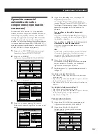
Page 141: ...io automático La función de inicio automático AUTO START le permitirá configurar el receptor para que comience a reproducir inmediatamente una fuente de programas específica cuando usted conecte la alimentación del receptor 1 Haga clic en FUNCTION del menú principal Aparecerá el menú FUNCTION SELECT 2 Haga clic en AUTO Aparecerá la pantalla AUTO START SETTING 3 Haga clic en el componente que desee...

Page 142: ...rámetros de visualización Utilice este procedimiento para seleccionar uno de los tres tipos de visualización AUTO OSD ERASE borrado de la visualización en pantalla POINTER ONLY puntero solamente o DEMO demostración Esto le permitirá cambiar al ajuste IR OUTPUT cuando utilice el repetidor de IR 1 Haga clic en FUNCTION del menú principal Aparecerá el menú FUNCTION SELECT 2 Haga clic en SET UP 3 Haga...

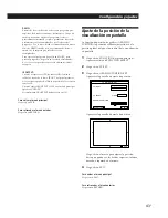
Page 143: ...es IR Cuando ajuste IR OUTPUT a OFF en el menú principal aparecerá IR OFF Normalmente IR OUTPUT deberá estar en ON Para volver al menú principal Haga clic en EXIT Para retroceder al menú anterior Haga clic en RETURN Ajuste de la posición de la visualización en pantalla La función de posición de gráficos GRAPHIC POSITION le permitirá realizar ajustes finos de la posición global del panel de control...

Page 144: ...discos láser LD Selecciona el reproductor de discos láser conectado a las tomas LD Teclas de componentes de vídeo 1 3 VIDEO 1 3 Selecciona los componentes de vídeo conectados a las tomas VIDEO 1 3 Tecla de escucha de cintas TAPE MONITOR Para escuchar fuentes de programas de audio durante la grabación Toma para auriculares PHONES Para conectar unos auriculares estéreo ª Interruptor de altavoces SPE...

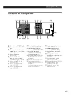
Page 145: ...PEAKERS Tomas para deck de cassettes TAPE Tomas para deck de cinta audiodigital deck de minidiscos DAT MD ª Tomas para reproductor de discos compactos CD º Tomas para giradiscos PHONO Terminales para antenas ANTENNA AM FM Terminal de puesta a tierra SIGNAL GND y Descripción del panel posterior 1 2 3 4 6 5 7 8 9 0 ª º 9 Toma de salida de audio para mezcla MIX AUDIO OUT 0 Terminales para altavoces d...

Page 146: ...ol BALANCE Se oye zumbido o ruido considerable Compruebe si los altavoces y los componentes están conectados con seguridad Compruebe si los cables conectores están alejados de un transformador o motor y a 3 metros por lo menos de un televisor o una lámpara fluorescente Aleje su televisor de los componentes de audio Cerciórese de conectar un conductor de puesta a tierra al terminal de tierra Las cl...

Page 147: ...place ambas por otras nuevas Conecte la antena de RC a la toma RC ANT del panel posterior del receptor STR DE905G solamente consulte al página 9 Elimine los obstáculos entre el telemando y el receptor STR DE805G solamente Elimine los obstáculos entre el telemando y la antena de RC STR DE905G solamente Cerciórese de que el telemando y el receptor estén ajustados al mismo número de seguridad STR DE9...

Page 148: ...s 1 kHz DIN 100 W 100 W Otros modelos 8 ohmios 20 H 20 kHz 120 W 120 W 8 ohmios a 1 kHz distorsión armónica total del 0 8 Excepto los modelos para Singapur y Malasia 160 W 160 W 8 ohmios 225 W 225 W 4 ohmios Menos del 0 3 PHONO Curva de ecualización de RIAA 0 5 dB CD TAPE DAT MD TV DBS LD VIDEO 1 2 10 Hz 50 kHz dB Paso directo Modo estéreo Modo perimétrico Salida de potencia dinámica Distorsión ar...

Page 149: ...podrá sentir realmente el tamaño y el tipo de una sala de conciertos Tipos de sonido Modo 3 CH LOGIC Seleccione el modo 3 CH LOGIC si posee altavoces delanteros y central pero carece de altavoces traseros El sonido del canal trasero saldrá a través de los altavoces delanteros para permitirle experimentar cierto sonido perimétrico sin utilizar altavoces traseros Tiempo de retardo Tiempo entre el so...

Page 150: ...central del delantero derecho y de los traseros En un sistema sin altavoz central modo PHANTOM El tono de prueba saldrá alternativamente a través de los altavoces delanteros y traseros Tiempo de reflexión cercana Tiempo Nivel Delantero izquierdo Delantero derecho 3 CH LOGIC NORMAL WIDE Reflexiones cercanas Reverberación Sonido directo E Edición Consulte Grabación Emisora memorizada 49 Exploración ...

Page 151: ...e emisiones Sintonía memorizada 27 Solución de problemas 46 Sonido perimétrico 30 49 Sonido perimétrico Dolby 32 49 modo central 32 49 T U V W X Y Z Telemando 14 23 40 42 código de seguridad 15 control de componentes que no sean Sony 17 19 22 control de componentes Sony 17 19 inserción de las pilas 14 operaciones sin televisor 40 sensibilidad 42 utilización 15 16 Tiempo de retardo 33 49 Tono de pr...

Page 152: ...C fiq uÆ A ßÏ Ì Y i µ q æ u fi C w ÿ Aæ æ æP Ò t æPºe uØ H w Ë V J W Æy C p G Y i Æy A fl z Jæ æ C ßÛ ACq uÆ A ß Í ÆÊ z A C w m æ ßO NÀm wÀ b pÆ Œæ oµ ØU Ø B C µ æ wm bq n Ïm œ Œ A ßK ønºˆ A H K µ µ æ œ Œÿ R C µ æ i Ò bæa Òºˆ a Ë A Œ µ Æg Ï ß Aàh Œ æ Ò R ª a Ë œ Œ C n bæ fl W Ôm F Ë A HßKÙ Ì qÆ y æ æ GªŸ C æ fi ß æ bs µ L Ê Æ A wnˆ º µ æ q ˆ q Æy W fi Uq u C M º æ æ fl A Ó O M Óæ A i Œn Ÿ M æتG...

Page 153: ...œ ŒŒØv wÆ æ 29 œ Œ Ù n fi 30 œ Œ w sµ n ı 30 Úß Ò M fiøË Ù n à ŒÆƒ G 32 wªs n ı 33 i æfiß œ ŒØ fi Ø 35 æfiß CD æ 37 PÆ Y Ê 38 a ˆ ß æfiß º Ê ßª æfiß 39 w M æ Œ qµ æ n ªª æfiß Ó æ 40 Ò H Ò t 41 q Æ A _ H _ 41 æ ªª æ F 42 øÔæ º 42 æ p à ı Ï m 43 ÍÆ e O ª 44 O ª 45 GªŸ M 46 WÆÊ 48 Nªy 49 Ø fi C ˆ Û ªª Æ ªª Æ Œ Ûª STR DE905G M STR DE805G C æ æ e O k U Wº º Cª Æ œ Oƒ Û STR DE905G A bæfiß W p Ù ÛÆt ß A ...

Page 154: ... µ æ O œ ŒØSÆÌ n Aµ W Ó fl C u nß µ æ µ Ï qµ æ A K i p à ı A zæfiß U ÿ s µµ n Aµ W Ê C Œªª æ h æ p à ı W w ߌ œ HøÔæ Ø C STR DE905G STR DE805G ªæ p Ãı i z Œ Û Ó n Aµ W Ê H Œ Ù Û L i Œ ı uªª æ Ó Àm A p æ µ C ˆ p Û b µ æ W Ó L Æe A ƒ6 Mƒ7 C PUSH ENTER M m  µ  µ M m ...

Page 155: ... pHALL THEATER ARENA µ A z u n bSOUNDFIELDSELECT à ı W øÔæ œ Œ A K i O Høæƒ nµÆƒ G C µ æ À ß Ò M fiøË Xæ A G i Y Œß Ò Ù nƃ Gø µ A qºv Æ ø µ ÿ C CD æ Ó s µ t ÓA1 l SonyCD æ A i ˆ r ß Aº r ß Œ s W s M s x bCD æ Í T C z i Œ µ æ ªª æ q p à ı øÔæ n Ò C ...

Page 156: ... œ 2 C 3 Ì z æ w Ï Y p à ı œ A ˆ Uªª æ ˆ sÆ A ı u IR ƒ æ K N IR Ó X e Ï Ì ÿ W œ 3 C p G Ãı Œ w µo ªª æ Æg W H ªŸ º F RC u W œ 1 CßÔ RC u Ë Ï Œ Nªª æ æ Ò RC u C p G ÿ Ø T ŒT o C ı u ƒ æ ı u Ó X S ß Ï F ÿ W ı u µ æ C s µØSÆÌ ı u ƒ æ a œ ÿ ƒ9 ßIR ƒ æ sµ C p G Y sµ ß p à ı Ó T Œ C F AßY ˆ s Aø ı u X ƒ19 ßµn O D Sony n Aµ W C 0 p P FUNCTION VOL ALL OFF USER SUB S O U N D 1 2 3 RC u qµ æ µ æ µ W H µ W H...

Page 157: ... e Ì ÿ W œ 3 C Ì ˆ U Ë V Ó Æ A p G X Ãı Œ w Ø æ ªª æ ı u IR X S ß F µ æ W ı u µ æ W œ 1 C Tª bªª æ M µ æ ß Oß_ S s b Ù ÛªŸ C p G ÿ Ø T ŒT o C ı u ƒ æ ı u Ó X S ß Ï F ÿ W ı u µ æ C s µØSÆÌ ı u ƒ æ a œ ÿ ƒ9 ßIR ƒ æ sµ C p G Y sµ ß p à ı Ó T Œ C F AßY ˆ s Aø ı u X ƒ19 ßµn O D Sony n Aµ W C qµ æ µ æ µ W H µ W H q X p à ı H Ê øÈ J IR ƒ æ M µ æ µ W H ø æ µ 0 p P FUNCTION VOL ALL OFF USER SUB S O U N D 2...

Page 158: ...C n µ W Ê C z i ˆ A à w º W A n s µ Ï µ æ Û sµ Ë kª i Ês µ C U Ïm M WŸ A ƒ45 ß O ª C l œ Œ H e µL ß Ûs µ A wnˆ º XÊ æ æ q C Dq u A Ød Ï s µ uß ß ß H Aà s µ C s µ TÍ T A HßKµo ÕÛ n Œæ n C Œ n µ Wlus µÆ A XæP Ô Ê æ æ W G µ W Ô A A n W Ô A ı k A n W Ô ı C sµ u 10 AM FM u ßCµ næ n æ R e næ L næ L CD æ dÆy DAT MDÆy L sµ n W Ê 10 næ e næ R sµ qµ æ ø æ 12 RC u sµ STR DE905G 9 qµ æ sµ næ t Œ 11 ø æ pÆgºv ...

Page 159: ... ø Ôµ n Ó C p G Ø ßQ a Ó s µ Ao iØ ƒ æ ı u IR H Ø F Ï ı u µ æ C Æ A æ U IR ƒ æ Ïm œ µ Ò n Ó C RC u sµ STR DE905G ß ª ª p Û N a RC u s µ Ï µ æ C ªª æ O ŒÆg W RF H Óæ æ C A b œ Œ ªª æ ß e A Nªª RC u s µ Ïæ æ W C W w s µ l Ïm A Uœ C sµ n œ RF Æg W H øÈF Ïà jƃ GÆ J N RC u m Ûªª H qÙ Uœ C ªª æ b Z RC u j 7m H æfiß œ Œ C p G b dÚà ßQ a Ó p Ãı Æ A æ U RC u Ë Ï H K Ú o Œ µ p C RC u n ƒ È j 50cm H W C RC ...

Page 160: ...M Ùߌ u ANTENNA FMæ u u a 1 FM 75Ω COAXIAL AM ANTENNA s µ næ u u A iØ œ O Ù C FM 75Ω COAXIAL AM ANTENNA AM Ùߌ u µ æ FM u s µ au æµo Õ Û n A s a u µL a Ï y µ a l C p Gs µµ u œ Œ A wns µ au H æp ª C µ y SIGNALGND H a u Ø Œ Û s µ C U Bnß ªÚ H p Gns µ L Ê AßY ß U æfiß C p G u Œ µ æ µæ Æ AßY µ Uß ƒ11 ßsµ næ tŒ C sµ n W Ê ßz ª ª p Ûß n W Ê s µ Ï µ æ C p G nß µ æ Ì Ò jæ ŒÆ AßY ß s µ C w Ïm A Uœ C Œ ªÚæ ...

Page 161: ...Ôæ æ SonyµP CD æ p G z CD æ COMMANDMODE Oº øÔ æ æ i bCD1 CD2 MCD3 ß øÔæ Æ A w N Oº Ï CD1 N æ s µ Ï µ æ W CD l C O A p G z aVIDEOOUT µ WøÈ X l Sony µPCD æ Æ A h N Oº w Û CD2 Œ CD3 N æ s µ Ï µ æ µ W Ê W ÆM l VIDEO1 VIDEO2 ŒLD C næ L R CD IN OUTPUT LINE L R L R TAPE IN REC OUT OUTPUT LINE LINE L R INPUT L R PHONO IN OUTPUT LINE L R sµ næ tŒ ßz ª ª p Ûß næ s µ Ï µ æ C e M k næ O A M næ hƒ øÔ Û C p À W...

Page 162: ... næ p G z qµ æ œ Œ næÆ iß ß s µ ÏSURROUNDOUTCENTER lß ß Ò M fiøË Ù n œ Œ ƒ32 C øÔæ ß ß e næ Œ IMPEDANCESELECTOR ß øÔ æ æ w p U Ì º C À d næ ª Æ S ø ß C µ Í T L b næ I º C p G z næ N IMPEDANCE ø ß O SELECTOR w Û 4 Ï8º ß 4 Ω 8º H W 8 Ω L ı R L ı R FRONT SPEAKERS R L µ æ e næ R e næ L REAR SPEAKERS L CENTER SPEAKER R næ R næ næ L µ æ INPUT MIX AUDIO OUT ßCµ næ µ æ VIDEO 1 VIDEO 2 LD MONITOR TV DBS MO...

Page 163: ... Ïm C 120V 220V 240V x s µAC q u N ª µ æ A M n µ W Ê ACq u µ Ï Wq Æy C p G NßO n W Ê s µ b µ æ SWITCHEDACOUTLETS A K i µ æ q µ s µµ Ê A A K i b ˆ µ æ q Æ A K i PÆ ˆ tŒ q C N Tª s µ b µ æ ACq Æy W Ê q O Æ Ø WLºg b O W ØS W º C ßO b Æy Ws µ ØSº ÆaÆxqæ A pqº Ê Aq Æ A Œqµ æ µ C U Bnß ªÚ H œ Œ µ æ e A U HTª Oß_ Óæ wß Ì C œ Œ µ æ e œ Œ µ æ e A Tª Oß_ß n U Cæfiß G NMASTERVOLUME Ï Ã Ï m 0 C N næ w Û ON C ...

Page 164: ... Œ6 Î C Ì z _ªª æ X p à ı Æ AßY b Æ Ø q C A H z Œªª æ p Aq ÿ R iØ Œ Ï3 Î C q ÆzÆ A b Ï p Ãı N b æ X LOW ßC iØ b Ø Ø µ ÿ Ê C Ì X EMPTY Æ AßY Ì q wß Ò q A ßY sq C µ ªª æ STR DE805G À q 1 ªª æ W ª l C 2 À J 3 R6 q A À Ô q œ A C 3 ˆ Wª l C ßK q GªGªk l aæ æ œ Œªª æÆ A Uq C q ÿ R œ Œ Sony SUM 3 NS q b ø æfiß œ Œ p U j Œ3 Î A p œ ŒSonyAM 3 NW P q h Œ6 Î C Ì z _ªª æ X p à ı Æ AßY b Æ Ø q C A H œ Œªª æ p ...

Page 165: ...ª æ C ß æfiß Æ A q Uq C z K N Ï p U ÆM ˆ C Œµß y Œ u ºu _ U w º r æA Ì ˆ U œ Ì C N ˆ U ÏÆ 0 A ˆ Qºu WÆ 15 C 5 s À W q ß ªª æ Ò m Z j 10 Ì C SECURITY NO w 0 1 2 3 4 5 7 6 8 9 10 11 12 13 15 14 4 3 2 1 4 3 2 1 4 3 2 1 4 3 2 1 4 3 2 1 4 3 2 1 4 3 2 1 4 3 2 1 4 3 2 1 4 3 2 1 4 3 2 1 4 3 2 1 4 3 2 1 4 3 2 1 4 3 2 1 4 3 2 1 ªª æ ªª æ ƒÚ ˆ w 0 p P FUNCTION VOL ALL OFF USER SUB S O U N D d f w Ï œ p Û œ Œ...

Page 166: ...Ì C ªª æ Æ k u ª ̪ª æ n fiæ w C e œ p U œ A ß d f w Ï W a ̪ª æ C p GÔ F df w Ï AÌæ ªª æÆ A w N Ø P Ë V a Hµ æ C S pß ªª æ p Uœ ß a kæ A w N Ø Mªª æß P Ë V æ C Ìß ªª æ Ò b Z W X ̃ ß A p à ı ßY Æ C n œ p Ãı Æ oß A i N wm Û œ A ˆ Ì df w Ï œÆ AµM Nªª æ Òm Z W ƒ Ò df w Ï C n I p à ı Æ A u n B ªª æ N i H C µ Ì ˆ Ì df w Ï Æ A w ÏmßY T w U C ßY œ T w U ªª æ A w b æÆ A i Hß ªª æ Òm Z W p Ãı Æ F Ó C h b ...

Page 167: ...SITION RETURN TV IR SET START Sony TV OTHER TV 1 VIDEO 3 2 TV INPUT µnO qµ æ Œ µ æ µn O SonyµP qµ æ Œ µ æ p G z Sony µP qµ æ i Œ ı uªª æ Ó A s µ b µ æ VIDEO1µ WøÈ J W A KµLª ß ı u IR X µn O ƒÚ F C U C p U K µn O Sonyqµ æ p G q L P µ WøÈ J pVIDEO2 s µµ Sony µPqµ æ Æ C O æAÌ æfiß A ˆ U C BJ1 Ï3 A df w Ï VIDEO123 H B J4 ø T µ WøÈ J AµM d f w ÏRETURN ŒEXIT C p G O Œºe à ıSonyqµ æ C øD w A Ë A Ms Y O æ...

Page 168: ...ßY œ qµ æ à ı W X F ßRELEASEYOURCOMMANDER ƒ Òªª æ A Y ı u X iØ º sµ ß C Æ A i A µ ı uXi ÊsX C p G ı uX µM Ø s µ AßY ˆ ƒ22 ßµ L ı u IR X sµ ß USER IR w z Ë kß C n q LµP qµ æ ßÔ Sonyqµ æ Æ N µ æ MONITOROUT s µ ÏSony qµ æ VIDEO 1øÈ J C ˆ B J1 Ï3 AµM b B J4 d f w ÏSONY TV C nÆ A d f w ÏVIDEO123 M ŒWIDE H w VIDEO1 M ŒWIDE CµM A d f w ÏRETURN ŒEXIT C 6 Ì PUSHYOURCOMMANDER X Û qµ æ à ı Æ AßY ˆ U Û j Ó qµ...

Page 169: ... n s µ VIDEO1 SonyµPVTR3 VHS VIDEO2 SonyµPVTR1 BETA VIDEO3 SonyµPVTR2 8mm LD SonyµPLD Ò tæ TV DBS SonyµPDBS µ æ DAT MD SonyµPDATÆy CD SonyµPCD æ CD1 TAPE Sony µP dÆy MONITOR SonyµP qµ æ q L VIDEO 1 b p U p U nµn O Sony Ìß SonyMDÆy s µ ÏDAT MD Æ s µ F aCONTROL A1 Æe Ø SonyµP µ T Æ C Ìß Sony s µ Ï e Ì C w H Æ p Aß Sony µP LD Ò tæ s µ Ï VIEDO 3 Æ C Ì HSony ßÛ DSony n W Œµ W Æ C µ p G z ø æ COMMANDCOD...

Page 170: ...µ C p G ÿ q M d f w Ϻt W H º r HøÔæ L º MµM A df w Ï TEST C p G ÿ µM q MßY ª Ì ı u Pæ H æ b sµ Lµ M d f w Ï ßOTHER µo Õ N æfiß MµM i Ê Ï BJ6 C Ì œ ŒßOÆaºtµP ø ºvÆyÆ øD w A Ë A Ms Y À d a ªª æ Oß_ Œ Œ1 M2 HøÈ J2 Ϻ qµ WD C Œ1 M2 N X S w sµ Û ªæ A Œ Ë i Ê U C NX sµ ß æfiß C 1 øÔæ ºt p W B J2 C 2 d f w Ï 2 CODESET N X w C EXIT 2 CODE SET RETURN OTHER TEST VCR MAKER SETTING PHILIPS ZENITH HITACHI SHA...

Page 171: ...N X C ßCODECLEAR T ßY X Û æ C n Ó Ÿ h NXÆ A df w Ï NO C n Ÿ h ı uXÆ 1 d f w ÏALLIRCODECLEAR C ßY X ßAreyousure H Sø H H K z T ª C 2 d f w ÏYES H Ÿ h N X C ßCODECLEAR T ßY X Û æ C n Ó Ÿ h NXÆ A df w Ï NO C 3 Ì qµ æ à ı X ßPUSH YOUR COMMANDER ˆ U Oæ Æ AßY ˆ U Ì Û b qµ æ à ı W º Ó ø æ ªª æ W s BJ6 C EXIT 2 CODE SETTING RETURN PUSH YOUR COMMANDER CODE CLEAR 2 CODE 2 1 CODE 6 Ì ßPUSHYOURCOMMANDER ˆ Uªª...

Page 172: ...ºv Ò tæ INPUT Aº r AENTER Æ A p J A p B J6 A Œ Ë kµ ı u X s µ ß C Y LºtµP pÆgºv Ò tæ M0 AßY œ q B J5 ºt W Ê µn O A iØ Ø Ú o ø T ß Œ C Æ A i Ê B J6 Œ Ë kµ M0 H Œ L Ù ÛQ Œ ÛpÆgºv ı uXsµ ß C p Gµn O F p TOSHIBA 2 Œ RCA 2 Ò t H A z K Ø Œ µ æ ªª æ h Œ ˆ º qµ æ q F Ì d f w ÏTESTÆ A q C Y ı u X AßY œ ßRELEASEYOURCOMMANDER ƒ Òªª æ X Û qµ æ à ı A µM iØ Ø a s nµ ß C Æ A Aµ ı uXsµ ß C p G ı uX µM Ø sµ ß Æ Aß...

Page 173: ...Xµ ß i O s j P C o µ ß p GÆ F M Ì z A qµ æ Æ M qµ à ıßY N X ßALLCLEAR C æ q ˆ œ Œ øW fl ı uX MßY œ æ u ˆ C p G Ø Œs Fq _ ˆµ ß ı uXˆ º z æ Æ M œ _ P k ßO a hs µq M _ ı uX C æ ªª æ æfiß ª Œ HD H ªP æ ª C ˆµM i Hµ æ æ ªª æ ı u X sµ ß M O Œ _ iØ Ø œ æ B ø C Y ªª æ Õ a ØSÆÌ iߌ ı uX M ªæ iØ Ø Hµn O C n W N Ucaseletters d f w ÏCAPS C p Gæfiß ø F d f w Ï Œ M N º æ Ï nßÔ r MµM d f w Ï ø T r Œ d f w Ï H Ÿ...

Page 174: ... nˆ º s µ Ê Æ d f w ÏALLOFF C p G Ê u b ˆ U Ò t Æ q A Ì AUTO PLAY ƒ41 ˆµ Æ A z d f w ÏALLOFF F Ø ˆ º Ê q C Æ A d f w Ï AµM w Ï Ò t C øÔæ Ê n Œ s µµ Ê Æ MßY Ø øÔ æ µ ÿ Ê d f w Ï n ÿ C l e M Tª Oß_ wß n U C J Oß_ p ƒ9 Ï13 z ø T B T a µ nRC u STR DE905G M ı uµoÆgæ M M Ê C µnOƒ17 Ï23 zs µµ Ê Œ ı u X C NMASTERVOLUME Ï Ã Ï m 0 HßK l a næ C 1 _ªª æ ˆ U Œ H µ æ q C z qµ æ N a q C p G qµ q M 17 Ï18 HµnO z ...

Page 175: ...ER VCR INPUT CH 0 1 2 Œ Sony µP qµ æ qµ ÿ Œ TV OUT Ì s µ F a TVOUT SonyµP qµ æ Æ A NTVOUT s µ Ï ªæ TV DBS IN AµM N TV DBS Ø w Û ßSonyTV C p K iøÔæ TV DBS Ø H qµ ÿ C Œ qµ æ VIDEOLABEL Ø N s µ b ªæ MONITOR OUT µ WøÈ J pVIDEO1IN w Û ßRECEIVER C p G z qµ æ S TVOUT A W ß qµ ÿ Œ À Û z ø ºvÆy qµ ø æ h qµ ÿ C ÓSonyµPDBS µ æ nØ ÓDBS µ æ e ADBS µ æ N Ì Ø Œ ı u IR X w Û ßSonyDBS C qµ æ Ø uºt w O w bSonyDBS n...

Page 176: ...Hz STEREO 4 d f w ÏSUB AµM d f w ÏTUNEMODE MANUAL AUTO HøÔæ ø º C øÔæ MANUAL Œ Û Ê n q xøÔæ C øÔæ AUTO Œ Û q xøÔæ C FUNCTION VOL ALL OFF USER S O U N D LIST BAND FM 102 50MHz STEREO EXIT MANUAL TUNE MODE AUTO 5 4 3 2 1 6 7 8 9 10 A B C SUB 5 df w Ï œ Œ Û Jq x Wv œ C USER LIST BAND FM 102 50MHz STEREO SUB Œ e O W ÓæøÔæ Ê 1 ˆ UPOWER A µ æ q C 2 ˆ U n Œ Ê J n Œ ˆ U ø ºv a VIDEO1 VIDEO2 ŒVIDEO3 pÆgºv ...

Page 177: ... EXIT A B C MEMORY 9 0 FM 96 00MHz FM 95 50MHz 8 d f w ÏMEMORY C MEMORY ßY ı C BAND FM 102 50MHz STEREO EXIT A B C MEMORY 9 0 FM 96 00MHz FM 95 50MHz 9 d f w Ï n s x q x 0 Ï9 C I G s J q x C VOL ALL OFF BAND FM 102 50MHz STEREO EXIT A B C MEMORY 3 4 5 6 7 2 1 8 9 0 FM 92 00MHz FM 94 50MHz FM 92 00MHz FM 89 50MHz FM 89 50MHz FM 104 50MHz FM 101 00MHz FM 96 00MHz FM 95 50MHz FM 102 50MHz 10 œ _ B J4...

Page 178: ...i H Æe ˆ aø s µ b µ æ W Ê C i µs µ Òt Mø Ê J øÔ æ F µ æ W ÿ A K i qßQ Œ U Ê W Óææfiß ºÀ b p Ãı Wi Êø µ Aºv M søË C l e A Tª Oß_ wæA Ì a s µ n Ê C ç G n W H c Gµ W H i Œ µ æ ø b d a W Aø bº r n W œ a DAT W AgßApÆg A Œø ºv a µ C nÆ A i ø µ Aºv Ê œ Œª Æ C 1 d f w Ï D µ ÿ Ê FUNCTION C 2 d f w Ï nø ÿ p ßLD C 3 d f w Ï ÛSUB C 4 d f w ÏRECEDIT ø µ ºv søË C Òt Œ Ê ÿ H ø µ Aºv Ê d Æy ADATÆy AMDø µ æ Aø æ c...

Page 179: ... EXIT SLEEP TIMER SETTING RETURN HOUR SLEEP MIN SEC 2 00 00 FUNCTION ALL OFF SLEEP n ø Ï3 œ Y d aÆy ø µ nÆ 1 d f w ÏEXIT C 2 d f w Ï D µ ÿ Ê FUNCTION C 3 d f w ÏTAPE C n Óø µ ºvÆ d f w Ïø µ À m p C n Ï _ Dµ ÿÊÆ C d f w ÏEXIT C µ ßY œø µ ºvÀm Ó O W s æfiß F Mø µ Ê µL nµ C ø µ ºv M z p G d f w Ï RECORDER Mø µ ºv H ßY N Q I _ C z p G d f w Ï FUNCTION MSOUND M Œ EXIT MØdµ REC EDIT µ ÿ Ê MßY œ e d f w ...

Page 180: ...n C n ÿ y J n ıÆ ƒ33 ß wªs n ı H æ n M Ù n º C ˆ Ù n ÍÆ ƒ49 Mƒ50 ßNªy C œ Œwsµ nı z u nÆ æ n Ò ÿøÔæ w sµ n ı K i Ê aßQ Œ Ù nƃ G F C 1 Òµ ÿ Æ M df w Ï Dµ ÿÊ SOUND C 2 d f w Ï n ıߌ HøÔæ n n ı C H e øÔº N C 3 œ _ d f w Ï MODE M q ߌ øÔæ n º C U œ Ì C n jßCµÆ i d f w ÏBASSBOOSTON C n Ï _ Dµ ÿÊÆ C d f w ÏEXIT C FUNCTION VOL ALL OFF USER SUB S O U N D 0 p P SOUND FIELD SELECT SOUND FIELD BASS BOOST PR...

Page 181: ... MONOMOVIE Ê n n Ò qºv Õºs jºv Ù Æ C MUSIC1 SMALL HALL A Ëߌµº U nµÆ CÃæA Û X M nµº C LARGE HALL MUSIC2 KARAOKE ÓÆz flÈ nµº n q nÆ Ò C ACOUSTIC A a µ Ó TONE º 2 W D fl È n C SPORTS ARENA A j ªR x µº Æ C ÃæA Û n uº C STADIUM A j S ƒvßfiı Æ CÃæA X Ûq l n C GAME GAME qqµ C n Û Ú oà jµTƒ ª C Œ Ù nƃ G ÒµÆ qMUSIC2øÔæ ßACOUSTIC næ C Ù nƃ GßYÆ O i æ µ ƒ33 C n ˆ º n ıÆ d f w ÏSOUNDFIELDON OFF C ...

Page 182: ...z p G e M næ µL næ e M næ µL næ e M næ A M p næ e M næ A M µ Û e n æ næ œ e næ øÈ X WD n C e næ øÈ X W D n e næ øÈ X WD ßCµ p næ Ø Õ ßCµ C næ Ú o ºeµ WdÚ ß Ò M fiøË Ù n C øÔæ PHANTOM H 3CHLOGIC 3 W D fiøË NORMAL ø WIDE ºe SUR EDIT CENTER TEST 0 dB SUR EDIT EXIT C MODE CENTER REAR RETURN VOL 0 dB 0 dB SOUND FIELD SELECT EXIT SOUND FIELD BASS BOOST PRO LOGIC MODE OFF OFF VOL ON ON SOUND FIELD SELECT...

Page 183: ...RETURN C SUR EDIT CENTER DELAY 0 dB SUR EDIT EXIT RETURN VOL DELAY DELAY SHORT LONG n N b œ Œ n ı Ï uºt wÆ d f w ÏSTD C æ µ i H æ næ µ C Æ æ U z ß æ µ Ë k i Ê æ C wªs n ı Cÿ nı ßt ß øæ ßCµ N µ N Œ µ M Ù n º i æ n µ A ÿ y ÿ n C i æ næ q LEVEL Mƃ G EFFECT Ù n º H wªs ÿæA X z p Û nı C wªsß n ı i s x b µ æ s xæ C D µ æ Q fi U q j g1 P A s x O Æ C æ µ æ e N N næ n œ Õà Œ µT C i æ ßtß Ò Ù n n ı µ C 1 l...

Page 184: ... w Ï D µ ÿ Ê SOUND C 2 d f w Ï n n ı ߌ C ßY e øÔº C 3 œ _ d f w ÏMODE HøÔæ n æ º C 4 d f w ÏSUR C ßY X SUREDIT µ ÿ Ê C n æ næ q Æ d f w ÏLEVEL AµM d f w Ï œ Œ H æ z flw næ q C n æ nµÆƒ Gq Æ d f w ÏEFFECT AµM d f w ÏUP ŒDOWN A ß n ı s b P æ ße z fl w q C nß b œ Œ n ı º uºt Ï w Æ d f w ÏSTD C nh X Dµ ÿÊÆ d f w ÏEXIT C n Ï _ e µ ÿ ÊÆ d f w ÏRETURN C n æ µqÆ d f w Ï VOL œ Œ C µ p Gs æ s J nı A H e w ...

Page 185: ... C WŸßY aQ s x U C nøÈ J Æ d f w Ï C n jºg M pºg r Æ d f w ÏCAPS C p GßÀø F d f w Ï Œ A æ º Ï nßÔ r AµM d f w Ï ø T r Œ d f w Ï H Ÿ h r C nh Ï e µ ÿÊÆ d f w ÏRETURN C nh X Dµ ÿÊÆ d f w ÏEXIT C µ w q x w W Ÿ 1 d f w ÏINDEXSETTING à ı LISTTUNER C ßY X w W v Ì C d f w ÏA NB N ŒC HøÔæ CµM A d f w Ï0 Ï9 HøÔæ n w W Ÿ q x C ƒÚ FUNCTION SELECT EXIT INDEX EXIT TUNER LIST INDEX SETTING RETURN EXIT INDEX SE...

Page 186: ...A G i h w W C 1 d f w ÏINDEXSETTING à ı W LISTCD C 2 d f w ÏDATALOAD C CD W Ÿº æ W A T ƒ A º æ ßY X ÛCDINDEXSETTING µ ÿ Ê C µ p GCD æ º bIRCODESETTING µ ÿ Ê µn O SonyCONTROLA1CD ƒ20 ŒCD æ S q A N X DATALOAD C CD æ p G º q Œ ºß CTRLA1s µÆ A DATALOADµ ß N _ß Œ ƒ11 C p G CD æ Oø p U r A à N b p à ı W _ G ä ö ü nh Ï e µ ÿÊÆ d f w ÏRETURN C nh X Dµ ÿÊÆ d f w ÏEXIT C µ DSonyµPCD æ Œ aCTRLA1 SonyµPCD æ C...

Page 187: ...ßY X INDEX SETTING à ı C 3 d f w ÏLISTCD C 4 d f w ÏSELECT AµM d f w Ï z n w Û s s C p G z n d f w Ï Œ œ H C 5 d f w Ï n wCD i h s W Ÿ C p A n wCD Ï ßGROUP1 s1 A S w Ï ßGROUP 4 Æ A df w Ï s WŸ œ Qº C n q Œ hº sæCD Æ d f w Ï º s W Ÿ œÆ º C nh Ï e µ ÿÊÆ d f w ÏRETURN C nh Ï Dµ ÿÊÆ d f w ÏEXIT C EXIT CD INDEX SETTING A F K P U B G L Q V C H M R W D I N S X E J O T Y 1 4 7 Z 2 5 8 0 3 6 9 b B RETURN C...

Page 188: ...d f w Ï DISC NUMBER A T Ì A ßY ˆº r ß X C d f w Ï Œ œ H AµM d f w Ï CßY l Ò µ C µ Û s µ CD æ 3 Œ5 æ µ A i Ø Ø Œ df w Ï WŸ høÔæ CD C Æ A q q CD Ó OøÔæ CD C p G CD æ OßO ºtµP A l Ò µ æfiß ß S O G1 ˆ Uº r ƒ ß H 2 ˆ U A Ì z d w Ï WŸÆ A iØ l Òµ C Æ A Ï _ Dµ ÿÊ A df w ÏSUB A ˆ q Ò µµ ß æfiß CD æ C PÆ Y Ê i Œ U C z Ë k PÆ Ò ÿ p A µ pÆg PÆ S ÒqÆgºv C Tª AUTOPLAY Ø Oß_ w Ûoff _ ƒ41 C 1 d f w Ï D µ ÿ Ê FUNC...

Page 189: ...F C µ p GøÔæ F a AUTO START Ø b Æ æfiß ßª MACRO ƒ41 A K Ø b ߪ øÔæ ALLOFF C 6 d f w Ï n ı u X C ı u X W ŸßY Hº ߪ B J X X U ߪ MACRO B J ßY Gº C 7 œ _ BJ5 M6 HøÈ Jà h8 ı uX C n Ÿ h øÈ J ı uXÆ 1 d f w Ï n Ÿ h N X œ Gº C 2 œ _ d f w Ï Œ NOSET X Û Ã ı k C 3 d f w ÏNOSET H Ÿ hº Û B J1 ı u X C n Ù N ß aøÈ J ı u X 1 d f w Ï s F ߪ MACRO C 2 œ _ d f w Ï Œ n ı u X X Û Ã ı C 3 d f w Ï ı u IR X C nÍ Êߪ æfi...

Page 190: ... Ë V Ó Œ k STR DE805G C øÔ ÿ Œÿÿæfiß ßYÆ æ ªª æ æ X Û æ C e O W Ûæfiß øO N I G C U ÿ æfiß p U C ÿ æ fi ß DAT MD p CD p TUNER PRESET PRESET PHONO µL TAPE 0 p n INPUTSELECT ALLOFF TVON VOLUME VOLUME MUTE 7 Ì n æfiß µ ÿ X Û æ Æ A d f w Ϫª æ C nøÔæ L ÿÆ 1 ÌINPUTSELECT X Û æ Æ A d f w Ϫª æ C 2 q Ï k æ ªª æ C Uÿ ÿ C X Û æ W C p G zøÔæ µ W ÿ A qµ æ TV ßY N a q C n æ Ø Æ Ì TV ON X Û æ Æ A d f w Ϫª æ Œø...

Page 191: ... Æ A _ H _ AUTO START _ Ø A i zß µ æ w q K flßY l Ò Y ØS w ÿ C 1 d f w Ï D µ ÿ Ê FUNCTION C ßY X FUNCTIONSELECT µ ÿ Ê C 2 d f w ÏAUTO C ßY X AUTOSTARTSETTING à ı C FUNCTION SELECT EXIT AUTO 3 d f w Ï n œ µ æ q K l Ò t Ê C uØ øÔæ ÿ C n b U µ æ q Æ AØ _ Ã Ò Ê Æ d f w ÏLAST C n b µ æ q Æ A Í Êߪ æfiß Æ ÌAUTOPLAY Ø µ M ÿ Q w MACRO PLAY w ƒ39 Æ M d f w ÏMACRO1 Œ MACRO2 C p G w LAST M h b ø µ æ Æ MßY N ...

Page 192: ...NCTION C ßY X FUNCTIONSELECT µ ÿ Ê C 2 d f w ÏSETUP C 3 d f w ÏAUTOOSDERASEON ŒOFF POINTER ONLYSET ŒDEMOSTART HøÔæ nÆ º C nÆ A i d f w ÏIROUTPUTON ŒOFF C EXIT SET UP RETURN AUTO PLAY FLASHER AUTO OSD ERASE FEELING POINTER ONLY IR OUTPUT DEMO 1 2 3 4 5 EXIT SET UP RETURN AUTO PLAY FLASHER AUTO OSD ERASE FEELING POINTER ONLY IR OUTPUT DEMO ON OFF ON OFF SET START AUTO OSD ERASE Ÿ h p à ı G Ò pÆgºv Æ...

Page 193: ...ETURN C DEMO d G ª º øE ª µ æ ÿ ÿ Ø ÿ C N Ì ÿ Æ A i Œ ÿ º æ h N e s x º æ p Ù n º C A Ì S sº æ A Œ ºg sº æ µL ˆ Ú nÆ A K u ŒDEMOº K i C d f w ÏSTART HøE ÿ C n Ó ÿÆ A df w Ï T ªª æ W s Œˆ º µ æ C IR OUTPUT ı uøÈ X G Ìß w ÛOFFÆ A h u q O W IROUT øÈ X ı u H C øÈ X ı u H C e O ı u ƒ æ N øÈ X ı u H C Ìß IROUTPUT w ÛOFF Æ A D µ ÿ Ê ßY X ßIR OFF C q A K ß IROUTPUT w ÛON µ q C n _ Dµ ÿÊÆ d f w ÏEXIT C nh ...

Page 194: ...Œ ˆ º n ı C 8 VIDEO3INPUT µ W3øÈ J Œ Ûs µƒ ø æ Œqµ C Àm µ C 9 PRESERTUNING œ w ø øÔæ w q x C 0 PHONO æ øÔæ s µ bPHONO æ C TUNER ø æ øÔæ ø æ C CD pÆg øÔæ s µ bCD CD æ C DAT MD º r n W œ a gßA pÆg øÔæ s µ Û DAT MD º r n W œ aÆy Œ g ßApÆg Æy C TV DBS qµ æ DBS º æ s µ bDBS DBS µ æ C LD qÆgºv øÔæ s µ bLD pÆgºv Ò tæ C VIDEO1 3 µ W øÔæ s µ ÛVIDEO1 3 µ W Ê C TAPE MONITOR œ a æ ø µ Œ Û n W ÿ C PHONES æ Œ Û...

Page 195: ...EO1 µ W1 9 MIXAUDIOOUT V W n WøÈ X 0 FRONTSPEAKERS e næ IMPEDANCESELECTOR ß øÔ æ æ ƒ12 VOLTAGESELECTOR q øÔæ æ Y ACq u SWITCHED AC OUTLETs ACq Æy Æy ߌ M Ïm à œ Œ ÿ ß CENTERSPEAKER n æ REARSPEAKERS næ TAPE œ a DAT MD º r n W œ a gßA pÆg ª CD pÆg º PHONO æ ANTENNA AM FM u T W ySIGNALGND H µ a l O ª 1 2 3 4 6 5 7 8 9 0 ª º ...

Page 196: ... µ æ q C µuÙ D ß A q C B k nµ ß ø Œ œ F C À d næ ªP Ê Oß_ T Í s µß Ì C æ BALANCE ø Ó C i σY Û n Œæ n C À d næ ªP Ê Oß_ T Í s µß Ì C s µæ u Oß_ª æ Œq æ A Oß_ qµ æ Œø øO 3 ê C Nqµ æ æ n W Ê Òm C u µ a l Oß_ s µ F µ a u C Y M ªÍ º F C Œ ª Ÿ s Î ø ß C næ S n µ C øÔæ PROLOGIC ŒMOVIE Ê n qºv n ı ƒ30 M31 C øÔæ æA Ì º ƒ32 C æA Ì a æ næ µ q ƒ32 C Ø i Êø µ ºv C À d Ê Oß_s µ øT C qFUNCTIONSELECTµ ÿ Ê Œ Œ Ø...

Page 197: ...f w Ï p à ı ˆ U p Ì Òø ºv aÆ M PÆ i Ê i jØ µ Ì C o ÿ H O _ Û e O W ı u ƒ æ M ı u µ æ ß z Z µ G Co Oæ æ GªŸ C p Gµo Õ ÿ H M is µ a ı u ƒ æ Àm ÛæAÌ Ïm C Ø Ú o Ù nƃ G C n ı Ø C Tª SPEAKERS næ øÔæ æ Oß_ w Û ON µ q C qµ Ãı WµLºv Œºv M C b µ æ WøÔæ æAÌ Ø C N qµ æ w æA Ì øÈ Jº C Nqµ æ Ò I µTÊ C Ì z œ Œªª æÆ M p Ãı ßYÆ STR DE905G C À dRC u Oß_ Ú T s µß Ì C Tª Oß_ S Ù Û ƒ È µ Ò RC u C Tª Uªª æ Oß_ Z RC u ...

Page 198: ... 15 kHz 0 5 dB 2 øÔæ 400kHzÆ 60dB AM ø æ ø dÚ øD w As Y A M Ë G 531 1602kHz 9 kHz j L G 531 1602kHz 9 kHz j 530 1610kHz 10 kHz j u Ù ß Œ u ƃ F 50dB m 1 000kHz Œ 999kHzÆ H æ Ò 54dB 50mV mÆ ø i Øu 0 5 H 50mV m 400kHz øÔæ 9kHzÆ G35dB 10kHzÆ G40dB 9 kHz M 10 kHz AM ø j M i H aßÔ C J Ù Û AM q x ß M ˆ º µ æ q C ˆ ÌPRESET ˆ UPOWER C Ì zßÔ F ø jÆ M w q x N Q Ÿ h C n jÆ M œ _ Pæfiß Ë k C øD w As Y A M Ë W...

Page 199: ...i Ú o ÿ ı P C Ì I næ w À b p Œ µ Ò z ÏmÆ A i N µøÆ A Ì w À b j Œª z Ï mÆ A h N µøÆ µu C ß Ò M fiøË Ù n qµ ÿ Mqºv Qº F b Ò Ù n ÿ X tŒ CªP q e ß Ò Ù n tŒ Ò _ Aoÿß Ò M fiøË Ù n H p U ÿ W DßÔ i F n G Ãı n Wƃ G A Ãı WÔ A Ï kƒ M µº W D C o WD i H ßÆ aBz nµ œ _ nH Ê Nµo Õ b qµ à ı ºÀ a GØu H C ßQ Œ ß Ò M fiøË A z m Ô I næ M Œ næ C øÔæ æA Ì º H K ß Ù nƃ G µT C ß Ò Ù n ØÎÆ O ÃßQ Œ ß Ò Ù n sX M X t Œ Cß Ò...

Page 200: ...q u 13 AM FM u 10 n W Ê 10 ı u IR ƒ æ 9 ß 8 RC u9 næ 11 qµ æ ø æ TV VCR 12 ø µ ºv 28 M N O NORMAL º 32 M49 P Q R PHANTOM º 32 M 49 e O 44 S n W Ê sµ 10 œ ŒØ fi Ø CD pÆg 36 w q x 27 ÿ 41 y CD LIST 38 w q x 26 ŒØv wÆ æ 29 n ı wªs 33 w sµ ß 30 3CH LOGIC º 32 M49 T U V W ø C µ ºsº æ µøÆ 33 p à ı 43 º 34 49 ªª æ F 42 næ µ q 32 M34 µ 33 µ q 32 u sµ AM FM u 10 RC u9 X ƃ Gq 34 M49 Mß iCD38 øÔæ Ê 24 Y µøÆ...

Reviews: