background image

Summary of Contents for STR-DE875

Page 1: ...4 234 334 12 i FM Stereo FM AM Receiver Operating Instructions STR DE975 STR DE875 0 2001 Sony Corporation ...

Page 2: ...EPTACLE OR OTHER OUTLET UNLESS THE BLADES CAN BE FULLY INSERTED TO PREVENT BLADE EXPOSURE For customers in the United States and Canada G ENERGY STAR is a U S registered mark As an ENERGY STAR partner Sony Corporation has determined that this product meets the ENERGY STAR guidelines for energy efficiency Don t throw a battery Pi it as the m ur ous wastes On safety l Should any solid object or liqu...

Page 3: ...aboratories Confidential unpublished Works 0 1992 1997 Dolby Laboratories All rights reserved Manufactured under licensefrom Digital Theater Systems Inc US Pat No 5 451 942 5 956 674 5 974 380 5 978 762 and other world wide patents issued and pending DTS ES and DTS Digital Surround are registered trademarks ofDigital Theater Systems Inc Copyright 1996 200O Digital Theater Systems Inc AU Rights Res...

Page 4: ... receiver replace all batteries with new ones Notes l Do not leave the remote in an extremely hot or humid place l Do not use a new battery with an old one l Do not expose the remote sensor to direct sunlight or lighting apparatuses Doing so may cause a malfunction l If you don t use the remote for an extended period of time remove the batteries to avoid possible damage from battery leakage and co...

Page 5: ...lied FM antenna adaptor l To prevent noise pickup keep the AM loop antenna away from the receiver and other components l Be sure to fully extend the FM wire antenna l After connecting the FM wire antenna keep it as horizontal as possible Outdoor FM antenna Ground wire not supplied To ground Important If you connect the receiver to an outdoor antenna ground it against lightning To prevent a gas exp...

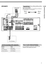
Page 6: ...a cord be sure to match the color coded pins to the appropriate jacks on the components White L Red R White L Red R Connect a To the Turntable CD or SACD player PHONO jacks CD SACD jacks If your turntable has a ground wire connect it to the h SIGNAL GND terminal on the receiver Tape deck TAPE jacks MD deck or DAT deck MD DAT jacks 6 ...

Page 7: ...appropriate jacks on the components k I2 White L White L s Red R Red R P CD or SACD player Ii Connect a Turntable CD or SACD player To the PHONO jacks CD SACD jacks tip a 1 ___ _ If your turntable has a ground wire connect it to the m SIGNAL GND terminal on the receiver MD deck or tape deck MD TAPE jacks 7 ...

Page 8: ...ou can display the SET LID SURR LEVEL and EQ parameters and the current soundfield by pressing ON SCREEN To the front pant Camcorder or video e game ST DE975 only I You can connect your TV s audio output jacks to the TV SAT AUDIO IN jacks on the receiver and apply sound effects to the audio from the TV In this case do not connect the TV s video output jack to the TV SAT VIDEO IN jack on the receiv...

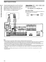
Page 9: ...g 2 Yellow video White L audio Red R audio Yellow video 3 White L audio Red R audio When making digital audio connections to a DVD player connect to either the coaxial OR optical digital jacks and not both It is recommended to make digital audio connections tothe coaxial jack mm 1 Please note that you cannot connect an LD player s DOLBY DIGITAL RF OUT jack directly to the receiver s digital input ...

Page 10: ...surround signal l To make a digital recording from your CD or SACD player connect the CD or SACD player s digital output directly to the digital input on your MD or DAT deck Refer to the instructions supplied with your CD or SACD player and MD or DAT deck for details l The DVD LD IN OPTICAL and COAXIAL jacks are compatible with 96 kHz 48 kHz 44 1 kHz and 32 kHz sampling frequencies The other OPTIC...

Page 11: ... details on the multi channel input hookups DVD player Audio cords not supplied Two for the MULTI CH IN FRONT and SURROUND jacks White L Red R White L a G Red R 4 5 Monaural audio cords not supplied Two for the MULTI CH IN CENTER and SUB WOOFER jacks s z Black P Black Video cord not supplied One for the DVD LD VIDEO IN jacks etc 0 a a Yellow Notes l When using the connections described below adjus...

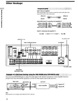
Page 12: ...dio Red R audio 0 Black control S 0 Black control S 0 Control 5 connecting cord supplied 1 Black P Black CONTROL Al II AC power cord CTRL s STATUS IN OUT AC0 I UTI I 2ND ROOM STR DE975 only Toaws Butlet You can use the 2ND ROOM jacks to output the audio signal of the selected component to a stereo amplifier located in another room Press 2ND ROOM repeatedly to switch the audio signal output to the ...

Page 13: ...cord away from the supplied audio video control S cablefor connection 0 Control S connecting cord Note Refer to the instructions supplied with your TV for details regarding the operations you can control from your lY l If you have a CONTROL Al II compatible Sony CD player SACD player tape deck or MD deck Use a CONTROL Al cord not supplied to connect the CONTROL Al II jack on the CD player SACD pla...

Page 14: ...io video components to the AC 3 OUTLET s on the receiver the receiver will supply power to the connected component s allowing you to turn the whole system on or off when you turn the receiver on or Off Caution Make sure that the total power consumption of the component s connected to the receiver s AC OUTLET s does not exceed the wattage stated on the mar panel Do not connect high wattage electric...

Page 15: ...buttons SET UP button Press to enter the setup mode when specifying speaker types and distances Cursor buttons I Use to select parameters after pressing the SET UP button Jog dial Use to adjust the setting of each parameter 15 ...

Page 16: ...8 ohm SPEAKERS CENTER terminals Active sub woofer SUB WOOFER AUDIO OUT jack See Speaker impedance on the next page You can connect an active sub woofer to either of the two jacks The remaining jack can be used to connect a second active sub woofer l Twist the stripped ends of the speaker cords about 2 3 inch 10 mm Be sure to match the speaker cord to the appropriate terminal on the components to a...

Page 17: ...ds are touching each other due to excessive removal of insulation After connecting all the components speakers and AC power cord output a test tone to check that all the speakers are connected correctly For details on outputting a test tone see page 23 If no sound is heard from a speaker while outputting a test tone or a test tone is output from a speaker other than the one whose name is currently...

Page 18: ...N 5 i Before using your receiver for the first time adjust SET UP parameters so that the receiver correspond to your system For the adjustable parameters see the table on page 62 See pages 19 23 for speaker settings and pages 51 52 for other settings Demonstration Mode The demonstration will activate the first time you turn on the power When the demonstration starts the following message appears i...

Page 19: ...ing the surround speakers behind you g When setting up the surround back speaker Set the speaker at least one meter b id the listening position It is recommended to place the speaker at an equal distance from the surround left or right speakers If there is no space behind the listening position set the speaker above the listening position by placing it on a stand or hanging it from the ceiling To ...

Page 20: ...NO This parameter can be set when the center speaker is set to NO and the surround speakers are set to LARGE or SMALL l If you connect a large speaker that will effectively reproduce bass frequencies select LARGE Normally select LARGE However if the front speakers are set to SMALL you cannot set the surround back speaker to LARGE l If the sound is distorted or you feel a lack of surround effects w...

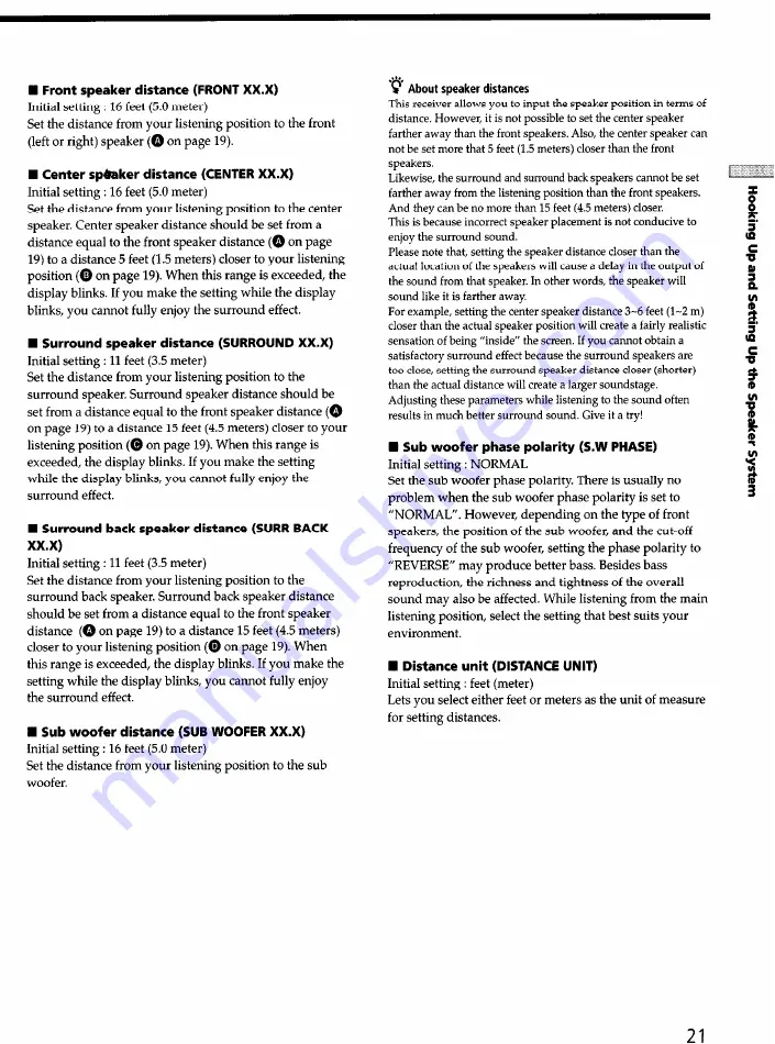
Page 21: ...his receiver allows you to input the speaker position in terms of distance However it is not possible to set the center speaker farther away than the front speakers Also the center speaker can not be set more that 5 feet 1 5 meters closer than the front speakers Likewise the surround and surround back speakers cannot be set farther away from the listening position than the front speakers And they ...

Page 22: ...ck speaker size is set to NO c About the surround speaker position SIDE MIDDLE and BEHIND This setting is designed specifically for implementation of the Digital Cinema Sound modes in the VIRTUAL sound fields With the Digital Cinema Sound modes speaker position is not as critical as other modes All of the modes in the VIRTUAL sound fields were designed under the premise that the surround speaker w...

Page 23: ...iver 2 Press TEST TONE on the remote TEST TONE appears in the display and you will hear the test tone from each speaker in sequence To change the test tone mode press the cursor buttons or to select the mode you want Mode The test tone output NORMAL The test tone is output from each speaker in sequence PHASE The test tone is output from two speakers at a time in sequence There is no sound output f...

Page 24: ...he display Check that the headphones are not connected to the PHONES jack No sound will come from the speakers if the headphones are connected I Check that the receiver is not in Demonstration Mode see page 18 There s no sound from a specific component Check that the component is connected correctly to the audio input jacks for that component Check that the cord s used for the connection is are fu...

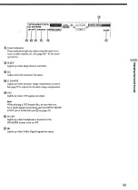
Page 25: ...name of the component or the preset station 00 4 FUNCTION button mdication or frequency Sound field applied to the program source q DIMMER button Press DIMMER repeatedly to adjust the brightness of the display 5 steps When set to the dimmest setting the display and the blue LED are turned off However when you press any button the display becomes the brightest setting temporary 25 ...

Page 26: ...ndicator This indicator lights up when the unit is decoding signals recorded in a multi channel format q Use the CINEMA STUDIO EX buttons to enjoy the CINEMA STUDIO EX sound effects AIWC buttons Press to activate the CINEMA STUDIO EX A B or C sound field page 32 q Use the SOUND FIELD buttons to enjoy surround sound For details see Enjoying Surround Sound starting from page 30 A F D button I indica...

Page 27: ...mponent you selected MODE button Press to select and play another video audio source in combination with the selected component Each time you press the button the display changes as folIows Press MODE to display And rotate FUNCTION to select VEXXX Any video source to enjoy with the audio from the selected component A XXX Any audio source to enjoy with the video from the selected comoonent q INPUT ...

Page 28: ...alizer using the EQ parameters page 38 the settings ace stored automatically and can be reproduced wherever you turn on the equalizer A B buttons Press to activate the DIGITAL CONCERT HALL A or B sound field page 32 q MULTVZCH A DIRECT button Press MULTl ZCH A DIRECT to enjoy the audio source connected to the MULTI CH IN jacks or analog 2 channel input jacks Only volume control and the front speak...

Page 29: ...age 38 The indicator on the button lights up and you can adjust the various equalizer parameters q SURR button Press to activate the surround parameters page 36 The indicator on the button lights up and you can adjust the various surround parameters effect level wall type etc q LEVEL button Press to activate the speaker level parameters page 37 The indicator on the button lights up and you can adj...

Page 30: ...usic etc sound modes are designed for use with standard audio sources and TV broadcasts They add reverberation to the source signal to make you feel as if you were in a concert hall or stadium etc Use these sound modes with two channel sources like CD and stereo broadcasts of sports programs or musical concerts For more information about the sound modes see pages 32 33 A F D The Auto Format Decodi...

Page 31: ...signals with a sampling frequency of 96 kHz are input the sound signals are output in stereo automatically and the sound field is turned off c You can identify Dolby Surround encoded software by looking at the packaging Dolby Digital discs are labeled with the F logo and Dolby Surround encoded programs are labeled with the wL logo P 6 1 channel matrix decoding Some movies released after the summer...

Page 32: ...th monaural soundtracks N STEREO MOVIE Creates a theater like environment from movies recorded with stereo soundtracks N V MULTI DIMENSION Virtual Multi Dimension m Uses 3D sound imaging to create an array of virtual surround speakers positioned higher than the listener from a single pair of actual surround speakers This mode creates 5 sets of virtual speakers surrounding the listener at approxima...

Page 33: ...rovided by the virtual speakers may cause increased noise in the play back signal l When listening to sound fields that employ the virtual speakers you will not be able to hear any sound coming m from the surround speakers Use the buttons on the front panel to operate the following modes A F D Auto Format Decoding Automatically detects the type of audio signal being input Dolby Digital DTS Dolby P...

Page 34: ...ing does not function for MPEG format signals 1 Lights up when the disc being played back contains the LFE Low Frequency Effect channel When the sound of the LFE channel signal is actually being reproduced the bars underneath the letters lights up to indicate the level Since the LFE signal is not recorded in all pacts of the input signal the bar indication will fluctuate and may turn off during pl...

Page 35: ... D RANGE Lights up when dynamic range compression is active See page 37 to adjust the dynamic range compression q DTS Lights up when DTS signals are input Note When playing a DTS format disc be sure that you have made digital connections and that INPUT MODE is NOT set to ANALOG see q on page 27 q 9 OFF Lights up when headphone is inserted or the SPEAKERS button is set to OFF Lights up when Dolby D...

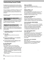
Page 36: ...s of the Dolby surround encoded flag l When set to OFF the receiver does not perform PRO LOGIC decoding Effect level EFFECT Initial setting depends on sound mode Lets you adjust the presence of the current surround effect Wall type WALL S I H Initial setting Midpoint Lets you control the level of the high frequencies to alter the sonic character of your listening environment by simulating a softer...

Page 37: ... woofer Low Frequency Effect LFE MIX XXX dB Initial setting 0 dB Lets you attenuate the level of the LFE Low Frequency Effect channel output from the sub woofer without affecting the level of the bass frequencies sent to the sub woofer from the front center or surround channels via the Dolby Digital or DTS bass redirection circuitry l For LFE mix level 0 dB outputs the full LFE signal at the mix l...

Page 38: ...ency of bass Front speaker midrange adjustment Level Frequency Lets you adjust the gain and frequency of midrange Front speaker treble adjustment Level Frequency Lets you adjust the gain and frequency of treble Center speaker bass adjustment Level Frequency Lets you adjust the gain and frequency of bass Center speaker midrange adjustment Level Frequency Lets you adjust the gain and frequency of mi...

Page 39: ...EMA STUDIO EX A 0 0 0 0 4 SEMI CINEMA STUDIO EX B 0 0 0 0 s P SEMI CINEMA STUDIO EX C 0 0 0 0 F NIGHT THEATER 0 0 0 0 i MONO MOVIE 0 0 0 0 P m STEREO MOVIE 0 0 0 0 e V MULTI DIMENSION 0 2 VIRTUAL MULTI REAR 0 V SEMI M DIMENSION 0 VIRTUAL ENHANCED A 0 VIRTUAL ENHANCED B 0 DIGITAL CONCERT HALL A 0 0 0 DIGITAL CONCERT HALL B 0 0 0 CHURCH 0 0 0 0 OPERA HOUSE 0 0 0 0 JAZZ CLUB 0 0 0 0 DISCO CLUB 0 0 0 ...

Page 40: ...0 0 0 VIRTUAL ENHANCED B 0 0 0 0 0 DIGITAL CONCERT HALL A 0 0 0 0 0 02 0 0 DIGITAL CONCERT HALL B 0 0 0 0 0 l 0 0 CHURCH 0 0 0 0 0 l 0 0 OPERA HOUSE 0 0 0 0 0 l 0 0 JAZZ CLUB 0 0 0 0 0 02 0 0 DISCO CLUB 0 0 0 0 0 0 0 0 LIVE HOUSE 0 0 0 0 0 W 0 0 ARENA 0 0 0 0 0 02 0 0 STADIUM 0 0 0 0 0 W 0 0 GAME 0 0 0 0 0 0 0 0 HEADPHONE 2CH 0 0 HEADPHONE DIRECT 0 HEADPHONE THEATER 0 0 MULTI CH IN 0 0 0 0 0 G 2CH...

Page 41: ... 0 0 0 r MONO MOVIE 0 0 0 0 0 a 3 5 STEREO MOVIE 0 0 0 0 0 0 P V MULTI DIMENSION 0 0 0 0 0 0 6 5 VIRTUAL MULTI REAR 0 0 0 0 0 0 P V SEMI M DIMENSION 0 0 0 0 0 0 VIRTUAL ENHANCED A 0 0 0 0 0 0 VIRTUAL ENHANCED B 0 0 0 0 0 0 DIGITAL CONCERT HALL A 0 0 0 0 0 0 DIGITAL CONCERT HALL B 0 0 0 0 0 0 CHURCH a l l 0 0 l OPERA HOUSE 0 0 0 0 0 0 JAZZ CLUB 0 0 0 0 0 0 DISCO CLUB 0 0 0 0 0 0 LIVE HOUSE 0 0 0 0 ...

Page 42: ... EX C 0 0 0 0 0 0 F 2 NIGHT THEATER 0 0 0 0 0 0 e MONO MOVIE 0 0 0 0 0 0 i STEREO MOVIE 0 0 0 0 0 0 c V MULTI DIMENSION 0 z 0 0 0 0 0 VIRTUAL MULTI REAR 0 0 0 0 0 0 V SEMI M DIMENSION 0 0 0 0 0 0 VIRTUAL ENHANCED A 0 0 0 0 0 0 VIRTUAL ENHANCED B 0 0 0 0 0 0 DIGITAL CONCERT HALL A 0 0 0 0 0 0 DIGITAL CONCERT HALL B 0 0 0 0 0 0 CHURCH 0 OPERA HOUSE l 0 l 0 l 0 l 0 l 0 l JAZZ CLUB l l l l l l DISCO C...

Page 43: ...C IQ NIGHT THEATER 0 0 0 0 r MONO MOVIE 0 0 0 0 3 5 STEREO MOVIE 0 0 0 0 P V MULTI DIMENSION 0 0 0 0 v 5 VIRTUAL MULTI REAR 0 0 0 0 P V SEMI M DIMENSION VIRTUAL ENHANCED A VIRTUAL ENHANCED B DIGITAL CONCERT HALL A 0 0 0 0 DIGITAL CONCERT HALL B 0 0 0 0 CHURCH 0 0 0 0 OPERA HOUSE 0 0 0 0 JAZZ CLUB 0 0 0 0 DISCO CLUB 0 0 0 0 LIVE HOUSE 0 0 0 0 ARENA 0 0 0 0 STADIUM 0 0 0 0 GAME 0 0 0 0 HEADPHONE 2CH...

Page 44: ...n all available stations in your area see page 46 Preset Tuning After you have tuned in stations using Direct Tuning or Automatic Tuning you can preset them to the receiver see page 47 Then you can tune in any of the stations directly by entering its Z character code see page 47 Up to 30 FM or AM stations can be preset The receiver will also scan all the stations that you have preset see page 47 B...

Page 45: ...t all even when the FM broadcast is received normally press this button to turn on the STEREO indication FM Press to select the FM band AM Press to select the AM band MEMORY Uses for memorizing preset stations SHIFT Press to select a memory page A B or C for presetting radio stations or tuning to preset stations FUNCTION control Rotate to select the tuner or other sauce On the remote D TUNING Pres...

Page 46: ... B 5 If you ve tuned in an AM station adjust the direction of the AM loop antenna for optimum reception 6 Repeat Steps 2 to 5 to receive other stations p If you try to enter a frequency not covered by the tuning interval The entered value is automatically rounded up or down Tuning intervals for direct tuning are FM 5OkHz AM 10 kHz to change to 9 kHz see page 58 For details on the buttons used in t...

Page 47: ...n from Step 3 Press MEMORY again to store the station If MEMORY goes out before you can store the station start again from Step 3 Repeat Steps 2 to 6 to preset another station To change a preset number to another station Do Steps 1 to 6 to preset the new station to the number You can tune the preset stations either of the following two ways Scanning the preset stations 1 2 Rotate FUNCTION to selec...

Page 48: ...n naming preset stations or program sources Cursor buttons Use to move the cursor when naming preset stations or program sources FUNCTION control Rotate to select the tuner or other source SET UP button Press to enter the set up mode ENTER button Press to enter the completed name of the preset station or program source ...

Page 49: ...ct a character then press to move the cursor to the next position To insert a space Turn the jog dial until a blank space appears in the display you can find the space character between II and A If you ve made a mistake Press or repeatedly until the character to be changed flashes then turn the jog dial to select the right character Press ENTER Recording Your receiver makes it easy to record to an...

Page 50: ...is case you may not be able to record from the sources l You cannot record a digital audio signal using a component connected to the analog TAPE OUT STR DE975 onIy or MD DAT OUT SIX DE975 only or MD TAPE OUT STR DE875 only jacks To record a digital audio signal connect a digital component to the DIGITAL MD DAT OUT STR DE975 only or DIGITAL MD TAPE OUT SIX DE875 only jacks l Sound adjustments do no...

Page 51: ...S the surround back signals are output through the actual speaker lights up Lets you assign a function to MULTI CH You cannot assign TUNER or PHONO Press SET UP Press the cursor buttons or to select MULTI CH Turn the jog dial to select NONE VIDEO I VIDEO 2 VIDEO 3 STR DE975 only DVD LD TV SAT MDIDAT STR DE975 only TAPE STR DE975 only MD TAPE STR DE875 only and CDISACD When set to ON the sound fiel...

Page 52: ...n select either COLOR or MONOCHROME The default setting is COLOR 1 Press SET UP 2 Press the cursor buttons or to select OSD 3 Turn the jog dial to select COLOR or MONOCHROME This parameter lets you adjust the position of the on screen display horizontally The default setting is 4 1 Press SET UP 2 Press the cursor buttons or to select OSD H POSITION 3 Turn the jog dial to select O 64 This parameter...

Page 53: ... recent Sony components Components with CONTROL Al jacks are compatible with components with CONTROLAlII and can be connected to each other Basically the majority of the functions available with the CONTROL Al control system will be available with the CONTROL Al II control system However when making connections between components with CONTROL Al jacks and components with CONTROL Al11 jacks the num...

Page 54: ... function buttons In this case refer to the Operating Instructions supplied with the receiver l When recording do not play any components other than the recording source It will cause the automatic function selection m to operate Iz a Synchronized recording f This function lets you conduct synchronized recording between the selected source and recorder components d s 1 Set the function selector on...

Page 55: ...or reversed I Check that the speakers and components are connected correctly and securely Adjust front balance parameter in the LEVEL menu Severe hum or noise is heard I Check that the speakers and components are connected securely z I Check that the connecting cords are away from a 5 transformer or motor and at least 10 feet 3 meters z away from a TV set or fluorescent light 5 I Move your TV away...

Page 56: ... the DIGITAL MD TAPE OUT terminals STR DE875 Radio stations cannot be tuned in I Check that the antennas are connected securely Adjust the antennas and connect an external antenna if necessary The signal strength of the stations is too weak when tuning in with automatic tuning Use direct tuning Make sure you set the tuning interval correctly when tuning in AM stations with direct tuning see pages ...

Page 57: ...O 1 VIDEO 2 VIDEO 3 10 Hz 50 kHz 0 5 2 dB with sound field and equalizer bypassed Inputs Analog PHONO Sensitivity 4 0 mV Impedance 50 kilohms S N 86 dB A 4 0 mVb I MULTI CH IN CD SACD DVD LD MD DAT MD TAPE TV SAT VIDEO 1 VIDEO 2 VIDEO 3 Sensitivity 250 mV Impedance 50 kilohms S N 96 dB A 250 mVb a Input short b Weighted network input level Inputs Digital DVD LD coaxial Sensitivity Impedance 75 ohm...

Page 58: ...eset stations will beerased when you change the tuning interval To reset the scale to 10 kHz repeat the procedure Inputs Video 1 Vp p 75 ohms S video Y 1 Vp p 75 ohms c 0 286 vp p 75 ohms Outputs Video 1 Vp p 75 ohms S video Y 1 Vp p 75 ohms c 0 2 vpp 75 ohms System Tuner section PLL quartz locked digital synthesizer system Preamplifier section Low noise NF type equalizer Power amplifier section P...

Page 59: ...take full advantage of Dolby Pro Logic Surround you should have one pair of surround speakers and a center speaker The surround speakers output monaural sound Dolby Digital This sound format for movie theaters is more advanced than Dolby Pro Logic Surround In this format the surround speakers output stereo sound with an expanded frequency range and a sub woofer channel for deep bass is independent...

Page 60: ...nd field 21 steps 36 WALL S 1 H 8 to 8 1 increment steps REVERB S 1 L 8 to 8 1 increment steps FRONT REVERB DRY WET STD SCREEN DEPTH DEEP MID OFF VIR SPEAKERS ON OFF LEVEL FRONT L I R 8 dB to 8 dB 1 dB steps 37 SURROUND L 1 R CENTER LEVEL XXX dB 8 dB to 8 dB 1 dB steps 10 dB to 6 dB 1 dB steps SURROUND LEVEL XXX dB 10 dB to 6 dB 1 dB steps SUM BACK LEVEL XXX dB 10 dB to 6 dB 1 dB steps S WOOFER LE...

Page 61: ...ps CENTER MID GAIN 10 dB to 6 dB 1 dB steps CENTER MID FREQUENCY CENTER TREBLE GAIN 198 Hz to 10 kHz 37 steps 10 dB to 6 dB 1 dB steps CENTER TREBLE FREQUENCY 1 0 kHz to 10 kHz 23 steps SURROUND BASS GAIN SURROUND BASS FREQUENCY 10 dB to 6 dB 1 dB steps 99 Hz to 1 0 kHz 21 steps SURROUND TREBLE GAIN 10 dB to 6 dB 1 dB steps SURROUND TREBLE FREQUENCY 1 0 kHz to 10 kHz 23 steps SURROUND BACK BASS GA...

Page 62: ...MALL NO LARGE SMALL NO YES NO 3 feet to 40 feet 1 foot steps 3 feet to 40 feet 1 foot steps 3 feet to 40 feet 1 foot steps 3 feet to 40 feet 1 foot steps 3 feet to 40 feet 1 foot steps NORMAL REVERSE feet meter SIDE MIDDLE BEHIND HIGH LOW HIGH LOW 40 Hz to 200 Hz 10 Hz steps 40 Hz to 200 Hz 10 Hz steps 40 Hz to 200 Hz 10 Hz steps 40 Hz to 200 Hz 10 Hz steps 40 Hz to 200 Hz 10 Hz steps AUTO ON OFF ...

Page 63: ...IDEO 1 Receiver VIDEO 2 Receiver VIDEO 3 Receiver DVDILD Receiver Turns the receiver on or off To watch VCR VTR mode 3 To watch VCR VTR mode 1 To watch VCR VTR mode 2 STR DE975 only To watch DVD or laser disc TV SAT CDISACD TUNER Receiver Receiver Receiver To watch TV programs or satellite receiver To listen to compact disc To listen to radio programs 4 Tape deck VCR LD player DAT deck Tape deck S...

Page 64: ...ut test tone Receiver EQONIOFF Remote Button MULTI 2CH A DIRECT Operations Receiver Function Selects MULTI CH IN and 2CH ANALOG DIRECT source MUTING Receiver Mutes the sound from the receiver AV DISPLAY TV VCR Selects information LD player displayed on the TV DVD player screen VCD player TITLE GUIDE DVD player VCR SAT Displays title and guide AV MENU DVD player VCR SAT Displays menu ON SCREEN Rece...

Page 65: ...he receiver Press 1 AVI or 2 AV2 while pressing down USE MODE The indicator lights once twice for AV2 then the command mode switches Setting to the 2nd room mode STR DE975 only You can use the remote to select the function for the 2nd room 2nd room mode You can use the function buttons only for the 2nd room Press 2ND ROOM while pressing down USE MODE STR DE975 only The indicator lights for a while...

Page 66: ...unction after programming Press the programmed button to activate the function you want If programming is unsuccessful check the following l If the indicator does not light up in step 1 the batteries are weak Replace both batteries l If the indicator flashes 4 times in quick succession while entering the numeric code an error has occurred Start again from step 1 Notes l The indicator turns off whi...

Page 67: ...FISHER 717 718 719 720 Maker Code s SONY 203 PIONEER 219 GENERAL ELECTRIC 721 722 730 GOLDSTAR 723 753 GRUNDIG 724 To control an MD deck HITACHI 722 725 729 741 Maker Code s SONY 301 DENON 302 ITT NOKIA 717 n JVC 726 727 728 736 B h MAGNAVOX 730 731 738 n Cc MITSUBISHI MGA 732 733 734 735 3 NEC 736 L 5 PANASONIC 729 730 737 738 739 740 0 PHILIPS 729 730 731 i PIONEER 729 s RCA I PROSCAN 722 729 73...

Page 68: ...ISHI MGA 503 519 544 NEC 503 520 544 PANASONIC 509 524 PHILIPS 515 518 PIONEER 509 525 526 540 RCAIPROSCAN 510 527 528 529 544 SAMSUNG 503 515 531 532 533 534 544 SANYO 508 545 SHARP 535 TELEFUNKEN 523 536 537 538 THOMSON 530 537 539 TOSHIBA 535 540 541 ZENITH 542 543 To control a satellite tuner or cable box Maker Code s SONY 801 802 803 JERR0LDlG I 806 807 808 809 810 811 812 813 814 PANASONIC 8...

Page 69: ...up to 80 buttons for the Learning function In some cases you may not be able to program even if you have not programmed 80 buttons l In steps 2 and 3 the indicator turns off while a valid button is pressed l In step 3 if several buttons that can be used for learning are pressed only the last pressed button is valid l In step 5 if a button that can be used for learning is pressed the new button is ...

Page 70: ...ough 3 to program up to 10 IR codes Tips l To program a function switch press the same function button twice in step 3 l If programming is unsuccessful check the following If the indicator does not light up in step 1 the batteries are weak Replace both batteries If the indicator lights 4 times in quick succession in step 3 an error has occured Start again from step 1 Note The indicator turns off w...

Page 71: ...Al II 13 speaker system 15 video components 8 Scanning I J K Indexing See Naming L M Labeling See Naming N 0 Naming preset stations 49 program sources 49 preset stations See Preset tuning radio stations See Automatic tuning Selecting component 27 sound field 31 Sleep timer 50 Sound field adjustable parameters 39 customizing 38 pre programmed 28 31 resetting 38 selecting 31 Speakers adjusting speak...

Page 72: ...Sony Corporation Printed in Malaysia http llwww world sony com ...

Page 73: ...TH ALL FAULTS or consumables such as fuses or batteries This warranty is valid only in the United States Proof of purchase in the form of a bill of sale or receipted invoice which is evidence that the unit is within the Warranty period must be presented to obtain warranty service This warranty is invalid if the factory applied serial number has been altered or removed from the Product REPAIR OR RE...

Page 74: ...is 6xWnit6s cYBnud s desmmbm elles ne se touchent pas et qu elles ne sont pas en contactaveclesbornesvokktes Para evitar el cortocircuito de los i de los cables de altavoces puede hiiar el e3ntodpllfl clor o attipS Pam evitarlo cons e la figma de la izqmerda y con co t j Per evitare di cortocircuitare i cavi diffusori Un cortocircuito nei cavi diffusori silenzia Yemissione de1 suono dai difhrsori ...

Page 75: ...INTHE UNITED STATES I BUSINESS REPLY MAIL FIRST CLASS MAIL PERMIT NO 138 PARK RIDGE N J I POSTAGE WILL BE PAID BY ADDRESSEE SONY ELECTRONICS INC 1 SONY DRIVE PARK RIDGE N J 07656 ATT CONSUMER AUDIO DIVISION lll l l ll l l ll l l l l l lII l II ...

Reviews: