background image

61

GB

C:\Documents and Settings\pc13\Desktop\Revision2_STR-
DG500\J9050000_2662258122DG500_GB\2662258122\GB05AMP_STR-DG500-CEL.fm

masterpage: Right

STR-DG500

2-662-258-

12

 (2)

O

the
r Op

er
atio

ns

Watching component 
images from other inputs


(COMPONENT VIDEO ASSIGN)

You can reassign a component video input to 
another input.

1

Press AMP MENU.

“1-LEVEL” appears on the display.

2

Press control button 

V

/

v


repeatedly to select “6-VIDEO”.

3

Press the control button or 
control button 

b

 to enter the 

menu.

4

Press control button 

V

/

v


repeatedly to select 


“COMP. V. A.”.

5

Press the control button or 
control button 

b

 to enter the 

parameter.

6

Press control button 

V

/

v


repeatedly to select the 
component video input you 
want to reassign (for example, 
DVD).

7

Press the control button or 
control button 

b

 to enter your 

selection.

8

Press control button 

V

/

v


repeatedly to select the input 
you want the component video 
input selected in step 6 
to be 
reassigned to (for example, 
VIDEO 1).

In this case, select “DVD–VD1”.

9

Press the control button to 
enter the setting.

When you press VIDEO 1, the image 
from the component connected to the 
VIDEO 1 jacks will be a component 
image. The input you can reassign to 
varies for each component video input. 
For details, see “Assignable inputs for 
component video input” be
low.

To return to the previous display

Press control button 

B

.

Assignable inputs for 
component video input

Notes

• You cannot reassign more than one component 

video input to the same input.

• You cannot use the component video input as the 

original input when it has been reassigned to 
another input.

Component 
video input

Assignable 
inputs

Display

DVD

VIDEO 1

DVD–VD1

VIDEO 3

DVD–VD3

DVD

DVD–DVD

MD/TAPE

DVD–MD

SA-CD/CD

DVD–CD

VIDEO 2

VIDEO 1

VD2–VD1

VIDEO 2

VD2–VD2

VIDEO 3

VD2–VD3

MD/TAPE

VD2–MD

SA-CD/CD

VD2–CD

GB01COV_STR-DG500-CEL.book  Page 61  Wednesday, December 28, 2005  9:47 AM

Summary of Contents for STR-DG500 - Multi Channel Av Receiver

Page 1: ... Sony Corporation 2 662 258 12 2 Multi Channel AV Receiver Operating Instructions Owner s Record The model and serial numbers are located on the rear of the unit Record the serial number in the space provided below Refer to them whenever you call upon your Sony dealer regarding this product Model No Serial No STR DG500 GB01COV_STR DG500 CEL book Page 1 Wednesday December 28 2005 9 47 AM ...

Page 2: ...a residential installation This equipment generates uses and can radiate radio frequency energy and if not installed and used in accordance with the instructions may cause harmful interference to radio communications However there is no guarantee that interference will not occur in a particular installation If this equipment does cause harmful interference to radio or television reception which ca...

Page 3: ...e D symbol are trademarks of Dolby Laboratories DTS DTS ES Neo 6 and DTS 96 24 are trademarks of Digital Theater Systems Inc This symbol on the product or on its packaging indicates that this product shall not be treated as household waste Instead it shall be handed over to the applicable collection point for the recycling of electrical and electronic equipment By ensuring this product is disposed...

Page 4: ...41 Settings for the video VIDEO menu 42 Settings for the system SYSTEM menu 43 Calibrating the appropriate settings automatically A CAL menu 47 Enjoying Surround Sound Enjoying Dolby Digital and DTS Surround sound AUTO FORMAT DIRECT 47 Selecting a pre programmed sound field 49 Using only the front speakers 2CH STEREO 52 Listening to the sound without any adjustment ANALOG DIRECT 52 Resetting sound...

Page 5: ...NING 2CH A F D MOVIE MUSIC MULTI CH IN DIRECT DISPLAY MULTI CHANNEL DECODING INPUT MODE INPUT SELECTOR MASTER VOLUME 1 3 2 4 6 8 7 5 9 q w qa qs qk ql qd qf qg qh qj PUSH Name Function A 1 Press to turn the receiver on or off page 25 32 33 53 55 72 B SPEAKERS OFF A B A B Press to select OFF A B A B of the front speakers page 26 C Display The current status of the selected component or a list of se...

Page 6: ...to the MULTI CH IN jacks page 31 K INPUT SELECTOR Turn to select the input source to playback page 31 32 33 52 54 57 58 60 62 63 64 L MOVIE MUSIC Press to select sound fields MOVIE MUSIC page 49 M A F D Press to select A F D mode page 47 N 2CH Press to select 2CH STEREO mode page 52 53 O TUNING Press to scan a station page 54 57 P TUNING MODE Press to select the tuning mode page 54 57 72 Q MEMORY ...

Page 7: ...ital format disc be sure that you have made digital connections and that INPUT MODE is not set to ANALOG page 60 E PRO LOGIC II IIx Lights up when the receiver applies Pro Logic processing to 2 channel signals in order to output the center and surround channel signals PRO LOGIC II lights up when the Pro Logic II Movie Music Game decoder is activated PRO LOGIC IIx lights up when the Pro Logic IIx M...

Page 8: ...put through the COAXIAL jack or when INPUT MODE is set to COAX IN page 60 N OPT Lights up when INPUT MODE is set to AUTO and the source signal is a digital signal being input through the OPTICAL jack or when INPUT MODE is set to OPT IN page 60 O SLEEP Lights up when the sleep timer is activated page 63 Name Function P Playback channel indicators L R C SL SR S SB The letters L C R etc indicate the ...

Page 9: ...R 3 4 A DIGITAL INPUT section OPTICAL IN jack Connects to a DVD player etc The COAXIAL jack provides a better quality of loud sound page 20 22 COAXIAL IN jack B ANTENNA section FM ANTENNA Connects to the FM wire antenna supplied with this receiver page 24 AM ANTENNA Connects to the AM loop antenna supplied with this receiver page 24 C AUDIO INPUT OUTPUT section AUDIO IN OUT jack Connects to an MD ...

Page 10: ... Blue Red Remote commander Name Function A AV 1 Press to turn on or off the Sonyaudio videocomponents that the remote is assigned to operate page 64 If you press 1 B at the same time it will turn off the receiver and other components SYSTEM STANDBY Note The function of the AV 1 switch changes automatically each time you press the input buttons W 1 2 3 4 6 7 8 0 10 ENTER 9 SYSTEM STANDBY TV VIDEO S...

Page 11: ...ess to adjust the volume level of all speakers at the same time Name Function L Press to skip tracks of the CD player DVD player MD deck or tape deck REPLAY ADVANCE Press to replay the previous scene or fast forward the current scene of the VCR or DVD player m M Press to search tracks in the forward backward direction of the DVD player fast forward rewind of the VCR CD player MD deck or tape deck ...

Page 12: ...satellite tuner CD player or MD deck channel numbers of the Digital CATV terminal CLEAR Press to clear a mistake when you press the incorrect numeric button return to continuous playback etc of the satellite tuner or DVD player T Numeric buttons number 5a Press to preset tune to preset stations select track numbers of the CD player DVD player or MD deck Press 0 10 to select track number 10 select ...

Page 13: ...uration AFront speaker L BFront speaker R CCenter speaker DSurround speaker L ESurround speaker R GSub woofer You can enjoy high fidelity reproduction of DVD software recorded sound in the Surround EX format if you connect one additional surround back speaker 6 1 channel see Using the surround back decoding mode on page 40 Example of a 6 1 channel speaker system configuration AFront speaker L BFro...

Page 14: ...with an auto standby function turn off the function when watching movies If the auto standby function is set to ON it turns to standby mode automatically based on the level of the input signal to a sub woofer then sound may not be output VIDEO 1 MULTI CH IN FRONT CENTER SUB WOOFER SURROUND VIDEO IN AUDIO IN VIDEO IN VIDEO OUT VIDEO 2 AUDIO IN MD TAPE SA CD CD L R L R L R L L R R OUT IN IN VIDEO IN...

Page 15: ...MULTI CH OUTPUT jacks etc This connection is used to output audio decoded by the component s internal multi channel decoder through this receiver b Model equipped only with AUDIO OUT L R jacks etc The sound quality depends on the connecting jack Refer to the illustration that follows Select the connection according to the jacks of your components How to hook up your components Component With Page ...

Page 16: ...vel of the speakers and sub woofer using the controls on the connected component Connecting components with multi channel output jacks DIGITAL OPTICAL VIDEO 1 IN VIDEO 2 IN DVD IN COAXIAL AM ANTENNA VIDEO 1 VIDEO IN AUDIO IN AUDIO OUT VIDEO IN VIDEO OUT VIDEO 2 AUDIO IN MD TAPE SA CD CD L R L R R SUB WOOFER L L R R OUT IN IN VIDEO IN DVD AUDIO IN AUDIO OUT VIDEO OUT DVD IN VIDEO 2 IN MONITOR OUT C...

Page 17: ...IDEO 1 IN VIDEO 2 IN DVD IN COAXIAL AM ANTENNA VIDEO 1 MULTI CH IN FRONT CENTER SUB WOOFER SURROUND VIDEO IN AUDIO IN AUDIO OUT VIDEO IN VIDEO OUT VIDEO 2 AUDIO IN L R L R L R SUB WOOFER L R R OUT IN IN VIDEO IN DVD AUDIO IN AUDIO OUT VIDEO OUT DVD IN VIDEO 2 IN MONITOR OUT COMPONENT VIDEO Y ASSIGNABLE PB CB B Y PR CR R Y MONITOR CENTER SURROUND BACK SURROUND FRONT A R R L L SPEAKERS MD TAPE SA CD...

Page 18: ...isplay components such as a TV monitor or a projector to the MONITOR OUT jack on the receiver Turn on the receiver when the video and audio of a playback component are being output to a TV through the receiver If the power supply of the receiver is not on neither video nor audio is transmitted Reassigning video input signals to another input Component video input signals can be reassigned to anoth...

Page 19: ...via the receiver If the power supply of the receiver is not turned on neither video nor audio is transmitted Tip You can watch the selected input image when you connect the MONITOR OUT jack to a TV monitor Hooking up a TV monitor DIGITAL OPTICAL VIDEO 1 IN VIDEO 2 IN DVD IN COAXIAL AM ANTENNA VIDEO 1 MULTI CH IN FRONT CENTER SUB WOOFER SURROUND VIDEO IN AUDIO IN AUDIO OUT VIDEO IN VIDEO 2 AUDIO IN...

Page 20: ...ntil they click into place Do not bend or tie optical digital cords Tip All the digital audio jacks are compatible with 32 kHz 44 1 kHz 48 kHz and 96 kHz sampling frequencies Hooking up a DVD player DVD recorder AM ANTENNA MULTI CH IN FRONT CENTER SUB WOOFER SURROUND VIDEO IN AUDIO IN AUDIO OUT VIDEO IN VIDEO OUT VIDEO 2 AUDIO IN MD TAPE SA CD CD L R L R L R SUB WOOFER L L R R OUT IN IN VIDEO IN A...

Page 21: ...hat it can be displayed on the receiver s display For details see Naming inputs page 62 DIGITAL OPTICAL VIDEO 1 IN VIDEO 2 IN DVD IN COAXIAL AM ANTENNA MULTI CH IN FRONT CENTER SUB WOOFER SURROUND AUDIO OUT VIDEO IN VIDEO OUT VIDEO 2 AUDIO IN MD TAPE SA CD CD L R L R SUB WOOFER L L R R OUT IN IN VIDEO IN AUDIO IN DVD IN VIDEO 2 IN MONITOR OUT Y PB CB B Y PR CR R Y MONITOR CENTER SURROUND BACK SURR...

Page 22: ...mpatible with 32 kHz 44 1 kHz 48 kHz and 96 kHz sampling frequencies Hooking up a satellite tuner DIGITAL OPTICAL VIDEO 1 IN DVD IN COAXIAL AM ANTENNA VIDEO 1 MULTI CH IN FRONT CENTER SUB WOOFER SURROUND VIDEO IN AUDIO IN AUDIO OUT VIDEO IN MD TAPE SA CD CD L R L R L R SUB WOOFER L L R OUT IN IN VIDEO IN DVD AUDIO IN AUDIO OUT VIDEO OUT MONITOR CENTER SURROUND BACK SURROUND FRONT A R R L L SPEAKER...

Page 23: ...N COAXIAL AM ANTENNA MULTI CH IN FRONT CENTER SUB WOOFER SURROUND VIDEO IN AUDIO OUT VIDEO OUT VIDEO 2 AUDIO IN MD TAPE SA CD CD L R L R SUB WOOFER L L R R OUT IN IN DVD AUDIO IN DVD IN VIDEO 2 IN MONITOR OUT COMPONENT VIDEO Y ASSIGNABLE PB CB B Y PR CR R Y MONITOR CENTER SURROUND BACK SURROUND FRONT A R R L L SPEAKERS VIDEO 1 AUDIO IN L R AUDIO OUT VIDEO IN VIDEO OUT VIDEO IN VIDEO 3 IN PORTABLE ...

Page 24: ...er components Be sure to fully extend the FM wire antenna After connecting the FM wire antenna keep it as horizontal as possible OPTICAL VIDEO 1 IN VIDEO 2 IN DVD IN COAXIAL AM VIDEO 1 MULTI CH IN FRONT CENTER SUB WOOFER SURROUND VIDEO IN AUDIO IN AUDIO OUT VIDEO IN VIDEO OUT VIDEO 2 AUDIO IN MD TAPE SA CD CD L R L R L R SUB WOOFER L R OUT IN IN VIDEO IN DVD AUDIO IN AUDIO OUT VIDEO OUT DVD IN VID...

Page 25: ...ceiver for this operation 1 Press 1 to turn off the receiver 2 Hold down 1 for 5 seconds PUSH and ENTER appears on the display alternately 3 Press MEMORY ENTER After CLEARING appears on the display for a while CLEARED appears The following items are reset to their factory settings All settings in the LEVEL TONE SUR TUNER AUDIO VIDEO and SYSTEM menus The sound field memorized for each input and pre...

Page 26: ...e receiver replace all the batteries with new ones 6 Selecting the speaker system You can select the front speakers you want to drive Be sure to use the buttons on the receiver for this operation Press SPEAKERS OFF A B A B repeatedly to select the front speaker system you want to drive To turn off the speaker output press SPEAKERS OFF A B A B repeatedly until the SP A and SP B indicators on the di...

Page 27: ...ix the optimizer microphone to a tripod not supplied and place the tripod at your listening position Be sure to remove any obstacles in the path between the optimizer microphone and the speakers When you face the speaker towards the optimizer microphone you will get a more accurate measurement Press AUTO CAL The follwing appears on the display A CAL 5 t A CAL 4 t A CAL 3 t A CAL 2 t A CAL 1 Before...

Page 28: ...ay cyclically after each measurement process as follows Error code t blank display t error code t blank display a t PUSH t blank display t ENTER a Appears when there are more than one error code To rectify the error 1 Record down the error code 2 Press the control button 3 Press 1 to turn off the receiver 4 Rectify the error For details see Error code and remedies below 5 Turn on the receiver and ...

Page 29: ...und left speaker distance page 45 f For details refer Surround right speaker distance page 45 g For details refer Surround back speaker distance page 45 Warning code Explanation Solution WARN 40 The environment is noisy Make sure the environment is quiet during Auto Calibration WARN 60 The front speaker balance is out of range Reposition your front speakers c WARN 62 The center speaker level is ou...

Page 30: ...nt left t Center t Front right t Surround right t Surround back t Surround left t Sub woofer 6 Adjust the speaker levels and balance using the LEVEL menu so that the level of the test tone sounds the same from each speaker For details see Adjusting the level LEVEL menu page 38 Tips To adjust the level of all speakers at the same time press MASTER VOL You can also use MASTER VOLUME on the receiver ...

Page 31: ...he receiver To avoid damaging your speakers Before you turn off the receiver be sure to turn down the volume level Playback 1 2 3 4 6 7 8 0 10 ENTER 9 SYSTEM STANDBY VIDEO 1 VIDEO 2 VIDEO 3 DVD 2CH A F D RETURN EXIT TV CH PRESET TV CH PRESET REPLAY ADVANCE MENU MOVIE MUSIC MEMORY DVD MENU CLEAR TOOLS DISPLAY MUTING TV VOL MASTER VOL FM MODE D TUNING D SKIP DUAL MONO MD TAPE SA CD CD TUNER AMP MENU...

Page 32: ...D TAPE SA CD CD TUNER AMP MENU TV 1 1 F G g f H m M X x 5 10 5 5 3 2 3 Notes The operation is described for a Sony Super Audio CD player Refer to the operating instructions supplied with the Super Audio CD player or CD player Tips You can select the sound field to suit the music Refer to page 49 for details Recommended sound fields Classical HALL Jazz JAZZ Live concert CONCERT You can listen to th...

Page 33: ...V and DVD player Check the following if you cannot listen to multi channel sound Be sure the sound source corresponds to the multi channel format the MULTI CHANNEL DECODING lamp on the front panel lights up during playback Be sure this receiver is connected to the DVD player via a digital connection Be sure the digital audio output of the DVD player is set up properly Tips Select the sound format ...

Page 34: ...trol button or control button b to enter the parameter 6 Press control button V v repeatedly to select the setting you want The setting is entered automatically To return to the previous display Press control button B To exit the menu Press AMP MENU Note Some parameters and settings may appear dimmed on the display This means that they are either unavailable or fixed and unchangeable Amplifier Ope...

Page 35: ...vel SR LVL SUR R 10 dB to SUR R 10 dB 1 dB step SUR R 0 dB Surround back speaker level SB LVL SB 10 dB to SB 10 dB 1 dB step SB 0 dB Sub woofer level SW LVL SW 10 dB to SW 10 dB 1 dB step SW 0 dB Dynamic range compressora D RANGE COMP OFF COMP STD COMP MAX COMP OFF TONE 39 2 TONE Front speaker bass level BASS LVL BASS 6 dB to BASS 6 dB 1 dB step BASS 0 dB Front speaker treble level TRE LVL TRE 6 d...

Page 36: ...N AUDIO 41 5 AUDIO Digital audio input decoding prioritya DEC PRI DEC AUTO DEC PCM DEC AUTO for VIDEO 1 2 DEC PCM for DVD Digital broadcast language selectiona DUAL DUAL M S DUAL M DUAL S DUAL M S DUAL M A V Synca A V SYNC A V SYNC Y A V SYNC N A V SYNC N Naming inputsa NAME IN VIDEO 42 6 VIDEO Component video assigna COMP V A DVD VD1 DVD VD3 DVD DVD DVD MD DVD CD VD2 VD1 VD2 VD2 VD2 VD3 VD2 MD VD...

Page 37: ...ST 3 0 m DIST 10 ft Center speaker distancea b CNT DIST DIST xx m ft between front speaker distance and 1 5 m 5 ft 0 1 m 1 ft step DIST 3 0 m DIST 10 ft Surround left speaker distancea b SL DIST DIST xx m ft between front speaker distance and 4 5 m 15 ft 0 1 m 1 ft step DIST 3 0 m DIST 10 ft Surround right speaker distancea b SR DIST DIST xx m ft between front speaker distance and 4 5 m 15 ft 0 1 ...

Page 38: ...level x SR LVL Surround right speaker level x SB LVL Surround back speaker level x SW LVL Sub woofer level x D RANGE Dynamic range compressor Lets you compress the dynamic range of the sound track This may be useful when you want to watch movies at low volumes late at night Dynamic range compression is possible with Dolby Digital sources only COMP OFF The dynamic range is not compressed COMP STD T...

Page 39: ...e parameters see Navigating through menus page 34 and Overview of the menus page 35 SUR menu parameters x S F SELCT Sound field selection Lets you select the sound field you want For details see Enjoying Surround Sound page 47 Note The receiver lets you apply the last selected sound field to an input whenever it is selected Sound Field Link For example if you select HALL for the SA CD CD input the...

Page 40: ...are encoded with both 5 1 channel signals and an extension stream designed for returning those signals to 6 1 discrete channels Discrete 6 1 channel signals are DVD specific signals not used in movie theaters Notes There may be no sound from the surround back speaker in Dolby Digital EX mode Some discs have no Dolby Digital Surround EX flag even though the packages have Dolby Digital EX logos In t...

Page 41: ...name of preset stations For details see Naming preset stations page 58 Settings for the audio AUDIO menu You can use the AUDIO menu to make settings for the audio to suit your preference Select 5 AUDIO in the amplifier menus For details on adjusting the parameters see Navigating through menus page 34 and Overview of the menus page 35 AUDIO menu parameters x DEC PRI Digital audio input decoding pri...

Page 42: ...t is not delayed Notes This parameter is useful when you use a large LCD or plasma monitor or a projector This parameter is valid only when you use a sound field selected with the 2CH or A F D buttons This parameter is not valid when PCM 96 kHz DTS 96 24 or DTS 2048 signals are input the receiver performing DTS ES Matrix 6 1 decoding MULTI CH IN or ANALOG DIRECT function is selected x NAME IN Nami...

Page 43: ...ively reproduce bass frequencies select LARGE Normally select LARGE When the sub woofer is set to NO the front speakers are automatically set to LARGE SMALL If the sound is distorted or you feel a lack of surround effects when using multi channel surround sound select SMALL to activate the bass redirection circuitry and output the front channel bass frequencies from the sub woofer When the front s...

Page 44: ...ll cut the bass signal from that channel When the bass is cut from a channel the bass redirection circuitry sends the corresponding bass frequencies to the sub woofer or other LARGE speakers However since bass sounds have a certain amount of directionality it is best not to cut them if possible Therefore even when using small speakers you can set them to LARGE if you want to output the bass freque...

Page 45: ...t speakers Also the center speaker cannot be set more than 1 5 meter 5 feet closer from the front speakers Likewise the surround speakers can not be set further away from the listening position than the front speakers And they can be no more than 4 5 meter 15 feet closer This is because incorrect speaker placement is not conducive to the enjoyment of surround sound Please note that setting the spe...

Page 46: ...ects become unclear unless set to SIDE LO or SIDE HI Nevertheless each listening environment has many variables such as wall reflections and you may obtain better results using BEHD HI if your speakers are located high above the listening position even if they are located to the immediate left and right Therefore although it may result in a setting contrary to the above explanation we recommend th...

Page 47: ...RATION page 27 Enjoying Dolby Digital and DTS Surround sound AUTO FORMAT DIRECT The Auto Format Direct A F D mode allows you to listen to higher fidelity sound and select the decoding mode for listening to a 2 channel stereo sound as multi channel sound Press A F D repeatedly to select the sound field you want For details see Types of A F D mode page 48 Enjoying Surround Sound 1 2 3 2CH A F D MOVI...

Page 48: ...USIC PLII MS 5 channel Performs Dolby Pro Logic II Music mode decoding This setting is ideal for normal stereo sources such as CDs PRO LOGIC II GAME PLII GM 5 channel Performs Dolby Pro Logic II Game mode decoding This setting is ideal for game softwares Dolby Pro Logic IIx PRO LOGIC IIx MOVIE PLIIX MV 6 channel Performs Dolby Pro Logic IIx Movie mode decoding This setting expands Dolby Pro Logic ...

Page 49: ...nction for DTS format signals or for signals with a sampling frequency of more than 48 kHz Tip When a multi channel signal is input only Dolby Pro Logic IIx decoding is effective When you select decoding modes other than Dolby Pro Logic IIx multi channel sound being encoded is output Selecting a pre programmed sound field You can take advantage of surround sound simply by selecting one of the rece...

Page 50: ... music is featured in the soundtrack Music HALL HALL Reproduces the acoustics of a classical concert hall JAZZ CLUB JAZZ Reproduces the acoustics of a jazz club LIVE CONCERT CONCERT Reproduces the acoustics of a 300 seat live house Headphone HEADPHONE 2CH HP 2CH This mode is selected automatically if you use headphone when 2 channel mode page 52 A F D mode page 48 is selected Standard 2 channel st...

Page 51: ...eaters Cinema Studio Reverberation Reproduces the type of reverberation found in theaters The CINEMA STUDIO EX modes integrate these three elements simultaneously Notes The effects provided by the virtual speakers may cause increased noise in the playback signal When listening with sound fields that employ the virtual speakers you will not be able to hear any sound coming directly from the surroun...

Page 52: ...ut any adjustment ANALOG DIRECT You can switch the audio of the selected input to two channel analog input This function enables you to enjoy high quality analog sources When using this function only the volume and front speaker balance can be adjusted 1 Turn INPUT SELECTOR on the receiver to select the input you want to listen to in analog audio You can also use the input buttons on the remote 2 ...

Page 53: ...e built in tuner Before operation make sure you have connected the FM and AM antennas to the receiver page 24 Tip The tuning scale for direct tuning differs depending on the area code as shown in the following table For details on area codes see page 3 The AM tuning scale can be changed page 73 1 AUTO CAL MIC SPEAKERS OFF A B A B PHONES VIDEO 3 IN PORTABLE AV IN VIDEO L AUDIO R MEMORY ENTER TUNING...

Page 54: ... on the display do not light up Enter the frequency of a station directly by using the numeric buttons 1 Press TUNER repeatedly to select the FM or AM band You can also use INPUT SELECTOR on the receiver 2 Press D TUNING 3 Press the numeric buttons to enter the frequency Example 1 FM 102 50 MHz Select 1 b 0 b 2 b 5 b 0 Example 2 AM 1 350 kHz Select 1 b 3 b 5 b 0 If you have tuned in an AM station ...

Page 55: ...ea code CEL CEK only This function lets you store up to 30 FM and FM RDS stations in alphabetical order without redundancy Additionally it only stores the stations with the clearest signals If you want to store FM or AM stations one by one see Presetting radio stations page 56 Be sure to use the buttons on the receiver for this operation 1 Press 1 to turn off the receiver 1 AUTO CAL MIC SPEAKERS O...

Page 56: ...tion except 1 If you move to another area repeat this procedure to store stations in your new area For details on tuning the stored stations see Tuning to preset stations page 57 If you move the antenna after storing stations with this procedure the stored settings may no longer be valid If this happens repeat this procedure to store the stations again Presetting radio stations You can preset up t...

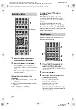
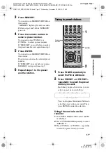
Page 57: ...other station 1 Press TUNER repeatedly to select the FM or AM band 2 Press PRESET or PRESET repeatedly to select the preset station you want Each time you press the button you can select a preset station as follows You can also press the numeric buttons to select the preset station you want Then press ENTER to enter the selection Using the controls on the receiver 1 Turn INPUT SELECTOR to select t...

Page 58: ... an index name Press control button V v to select a character then press control button B b to move the cursor to the next position If you made a mistake Press control button B b until the character you want to change flashes then press control button V v to select the correct character Tip You can select the character type as follows by pressing control button V v Alphabet upper case t Numbers t ...

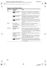
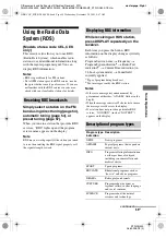
Page 59: ...Y repeatedly on the receiver Each time you press the button RDS information on the display changes cyclically as follows Program Service name t Frequency t Program Type indicationa t Radio Text indicationb t Current Time indication in 24 hour system mode t Sound field currently applied a Type of program being broadcast b Text messages sent by the RDS station Notes If there is an emergency announce...

Page 60: ... modes may not be set up depending on the input VARIED Other types of programs such as celebrity interviews panel games and comedy POP M Popular music programs ROCK M Rock music programs EASY M Easy Listening LIGHT M Instrumental vocal and choral music CLASSICS Performances of major orchestras chamber music opera etc OTHER M Music that does not fit into any categories above such as Rhythm Blues an...

Page 61: ... repeatedly to select the input you want the component video input selected in step 6 to be reassigned to for example VIDEO 1 In this case select DVD VD1 9 Press the control button to enter the setting When you press VIDEO 1 the image from the component connected to the VIDEO 1 jacks will be a component image The input you can reassign to varies for each component video input For details see Assig...

Page 62: ...acter Follow the procedure given in To create an index name page 58 To return to the previous display Press control button B Changing the display You can check the sound field etc by changing the information on the display Be sure to use the buttons on the receiver for this operation Press DISPLAY repeatedly Each time you press the button the display changes cyclically as follows All inputs except...

Page 63: ... onto a MiniDisc or audio tape using the receiver See the operating instructions supplied with your MD deck or tape deck 1 Press one of the input buttons to select the playback component You can also use INPUT SELECTOR on the receiver 2 Prepare the playback component for playing For example insert a CD into the CD player 3 Prepare the recording component Insert a blank MD or tape into the recordin...

Page 64: ...opy guards to prevent recording In this case you may not be able to record from the source The audio signals input to the MULTI CH IN jacks are not output from the analog AUDIO OUT jacks even when MULTI CH IN is selected The analog audio signals of the current or previously used input are output Changing button assignments You can change the factory settings of the input buttons to suit the compon...

Page 65: ...o signal information The luminance signal Y and chrominance signal C are combined and transmitted together x Dolby Digital Digital audio encoding decoding technology developed by Dolby Laboratories Inc It consists of front left right center surround left right and sub woofer channels It is a designated audio standard for DVD video and also known as 5 1ch surround Since surround information is reco...

Page 66: ... of 96kHz 24bit which is the highest possible for DVD video The number of playback channels varies depending on the software x DTS Neo 6 This technology converts 2ch stereo recorded audio for 6 1ch playback There are two modes to select according to the playback source or your preference CINEMA for movies and MUSIC for stereo sources such as music x DTS Digital Surround Digital audio encoding deco...

Page 67: ...usly use this receiver at a large volume the cabinet temperature of the top side and bottom rises considerably To avoid burning yourself do not touch the cabinet On placement Place the receiver in a location with adequate ventilation to prevent heat buildup and prolong the life of the receiver Do not place the receiver near heat sources or in a place subject to direct sunlight excessive dust or me...

Page 68: ...the front speakers Connect a pair of headphones to the PHONES jack to verify that sound is output from the headphones If only one channel is output from the headphones the component may not be connected to the receiver correctly Check that all the cords are fully inserted into the jacks on both the receiver and the component If both channels are output from the headphones the front speaker may not...

Page 69: ... woofer Check that the sub woofer is connected correctly and securely Make sure you have turned on your sub woofer Make sure the sub woofer is set to YES page 37 There is no sound from the sub woofer depending on the sound field The surround effect cannot be obtained Make sure the sound field function is on press MOVIE or MUSIC Sound fields do not function for signals with a sampling frequency of ...

Page 70: ...the appropriate input mode Move your audio components away from the TV Assign the component video input correctly The MULTI CHANNEL DECODING lamp does not light up in blue Check that the playback component is connected to a digital jack and the input is selected properly on this receiver Check whether the input source of the software being played back corresponds to the multi channel format Check ...

Page 71: ...NIC DISTORTION Models of area code U only With 8 ohm loads both channels driven from 20 20 000 Hz rated 100 watts per channel minimum RMS power with no more than 0 09 total harmonic distortion from 250 milliwatts to rated output Amplifier section Models of area code U CA Stereo Power Output1 Reference Power Output1 2 8 ohms 20 Hz 20 kHz THD 0 09 100 W 100 W 110 W ch 8 ohms 1 kHz THD 0 7 110 W 110 ...

Page 72: ...re may be no sound output 3 Measured under the following conditions Frequency response Analog 10 Hz 70 kHz 0 5 2 dB with sound field and tone bypassed Inputs Analog Sensitivity 500 mV 50 kohms S N4 96 dB A 500 mV5 Digital Coaxial Impedance 75 ohms S N 100 dB A 20 kHz LPF Digital Optical S N 100 dB A 20 kHz LPF Outputs Analog AUDIO OUT Voltage 500 mV 10 kohms SUB WOOFER Voltage 2 V 1 kohm Tone Gain...

Page 73: ...n Power consumption during standby mode 0 2 W Dimensions w h d Approx 430 157 5 316 mm 16 7 8 6 2 8 12 4 8 inches including projecting parts and controls Mass Approx 8 0 kg 17 lb 11 oz Supplied accessories FM wire antenna 1 AM loop antenna 1 Remote commander RM AAU005 1 R6 size AA batteries 2 Optimizer microphone ECM AC2 1 Design and specifications are subject to change without notice Area code Tu...

Page 74: ...nitial setup 25 INPUT MODE 60 M MD deck connecting 15 Menu A CAL 47 AUDIO 41 LEVEL 38 SUR 39 SYSTEM 43 TONE 39 TUNER 41 VIDEO 42 Muting 31 N Naming 58 62 R RDS 59 Recording onto a MiniDisc or audio tape 63 onto a recording media 64 S Satellite tuner hooking up 18 Selecting component 31 sound field 49 speaker system 26 Sleep Timer 63 Sound fields resetting 53 selecting 49 Speakers connecting 14 Sup...

Page 75: ...ettings pc13 Desktop Revision2_STR DG500 J9050000_2662258122DG500_GB 2662258122 GB01COV_STR DG500 CELIX fm masterpage Right STR DG500 2 662 258 12 2 GB01COV_STR DG500 CEL book Page 75 Wednesday December 28 2005 9 47 AM ...

Page 76: ...ings pc13 Desktop Revision2_STR DG500 J9050000_2662258122DG500_GB 2662258122 GB06BKC_STR DG500 CEL fm Sony Corporation Printed in Malaysia model name1 STR DG500 2 662 258 12 2 GB01COV_STR DG500 CEL book Page 76 Wednesday December 28 2005 9 47 AM ...

Reviews: