background image

Summary of Contents for STR-DG510

Page 1: ... s Record The model and serial numbers are located on the rear of the unit Record the serial number in the space provided below Refer to them whenever you call upon your Sony dealer regarding this product Model No Serial No STR DG510 2007 Sony Corporation ...

Page 2: ...These limits are designed to provide reasunahle protection against harmfifl interli rence in a residential installation This equipment gmmmtes uses and c m radiate radio frequency energy rod if not installed and used in accordance with the instructions may cause harmlifl interference to radio communications However them is i1o guarantee that interference will not occur in a particular installation...

Page 3: ... wer right corner of the front p meh In this manual models of area code U is used fl r illustration purposes unless stated otherwise Any difl crm ce in operation is clearly indicated in the text for example Models of area code CEL only The instructions in this manual describe the controls on the supplied remote You can also use the controls on the receiver if they have the same or similar names as...

Page 4: ...Note for the supplied remote RM AAU013 Tile VIDEO 3 button on tile remote is not available l _r receiver operation 4 GB ...

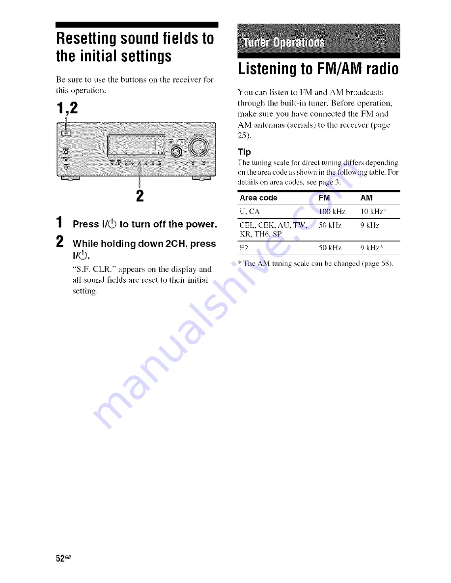
Page 5: ...u 41 Settings for the audio AUDIO menu 41 Settings for the system SYSTEM menu 42 Calibrating the appropriate settings automatically CA CAL menu 46 Enjoying Surround Sound Enjoying Dolby Digital and DTS Surround sound AUTO FORMAT DIRECT 46 Selecting a pre programmed sound field 48 Using only the front speakers 2CH STEREO 51 Listening to the sound withont any adjustment ANALOG DIRECT 51 Resetting so...

Page 6: ... informatiuu displayed on the display page 57 59 INPUT MODE Press to select theinput mode when the same cumpuueuts are connected to both digital and analog jacks page 58 Name Function MASTER Turn tu adjust the vohmm VOLUME level of all speakers at the same time page 32 33 34 35 DIRECT Press to listen to high qualit analog sound page 51 AUTO CAL Press to activate the Auto Calibration luuctiou page ...

Page 7: ...NG MODE TUNING AUTO CAL MIC jack Function Press to operate the tuner FM AM page 52 Connects to the supplied optimizer microphone for the Auto Calibration function page 28 PHONES jack _onneclsto headphones page 64 o 5 r 7 G8 ...

Page 8: ...ights up when the receiver applies Pro Logic processing to 2 channel signals in order to output the center and surround channel signals Flrt PLII lights up when the Pro Logic II Movic Music decoder is activated However these indicators do not light up if both the center aud surrouud speakers are set to NO page 38 and you select a sound field using the A F D button OPT DTS Lights up when VIDEO 2 in...

Page 9: ...vated page 37 COAX Lights up when DVD input is selected However UNLOCK appears on the display if no digital signal is input through the COAXIAL jack Playback The letters L C R etc channel indicate the channels being indicators played back The boxes around the letters vary to show how the receiver dowumixes the source sound based on the speaker settings L Front Lett R Front Right C Center monaural ...

Page 10: ...PUT OUTPUT section Green Y COMPONENT Connects to a DVD VIDE player TV era Blue INPUT satellite tuner Yeu O PdGB OUTPUT carl eltjoy high jacks _ quality image page Red 2 1 21 23 PR CR SPEAKERS section Celnlects to speakers page 15 _ Cenrlects to a sub woeler page 15 VIDEO AUDIO INPUT OUTPUT section White L AUDIO IN OUT jacks Red R Connects to aVCR a DVD player etc page 20 24 Yellow VIDEO IN OUT jac...

Page 11: ...ntenna aerial supplied with this receiver page 25 You can watch the selected inpul image when you connect Ihe MONITOR OUT or HDMI OUT jack to a TV or proiector page 18 20 Yon can use the supplied remote if RM AAU013 to operate the receiver and to control the Sony audio video components that the remote is assigned to operate page 61 I D IN continued 11G8 ...

Page 12: ...alcllile Receiver TV TV SA CD CD Super Audio CD CD player TUNER Built in luner Name Function 2CH Pressto select a sound field A F D MOVIE MUSIC AMP MENU Press to display the mmm of the receiver Then use It _ _ _and _ _ to perl_ rm menu operations FM MODE Press to select the FM monaural or stereo reception D TUNING Press to enter direct tuning mode D SKIP Press to skip a disc when using a multi dis...

Page 13: ... _ and to perform menu uperations Name Function RETURN EXIT G i _ DISPLAY TOOLS Press Io return tu the previous menu 0 exil the menu while the nmuu or on screeu guide of 5 the VCR DVD player satellite turJer or blu ray disc player is displayed on the TV screen D Press RETURN EXIT and TV at the same time tu relurn lu the previous menu or exit Ihe TV s menu while Ihe menu is displayed on the TV scre...

Page 14: ...e the Auto Calibration function a The number 5 MASTER VOL TV VOL and D buttons have tactile dots Use the tactile dots as reti rences when operating the receiver Notes Some functions explained in this section may not work depending on the model The above explanation is intended to serve as an example only Therelore depending on the compoimnt the above operation may not be possible or may operate di...

Page 15: ...e an additional front speaker system connect them to the SPEAKERS FRONT B terminals You can select the h unt speakers you want to use with SPEAKERS OFF A B on the receiver page 27 b When you cunnect a sub wuofcr with an auto standby fimctiun turn oft the flmction when watching movies If the auto standby function is set to on it turns to standby mode automatically based on the level of the input si...

Page 16: ...he following illustration shows how to connect a Super Audio CD CD player After connecting your Super Audio CD CD player proceed to 3b Connecting the video components page 17 Super Audio CD player CD player OAudio cord not supplied 16G8 ...

Page 17: ...the antennas aerials page 25 Component to be connected Component Page With HDMI jack 18 TV 20 DVD player DVD recorder 21 Satellite tuner Set top box 23 VCR 24 The linage quality depends on the connecting jack Refer to the illustration that follows Select the connection according to the jacks oil your components TV etc INPUT jack COMPONENT COMPONENT MONITOR OUT HDMI VIDEO HDMI OUT jack VIDEO Receiv...

Page 18: ... signals in digital format DVD player Audio signals Audio video _c_ _ _signals e Blu ray disc player Audio video Audio signals _ _ signals TV projector etc Audio video signals OCoaxial digital cord not supplied O HDMI cable not supplied We reconnnend that you use a Sony HDMI cable OOptical digital cord not supplied 18 G8 ...

Page 19: ...able This receiver may not be able to transfer video or audio signals with certain types of components Refer to the operating instructions of each component connected for details Notes Be sure to turn on the receiver when the video and audio signals of a playback component are being output to a TV via the receiver Unless the power is turned on neither video nor audio signals will be transmitted Wh...

Page 20: ...the receiver Unless the power is turned on neither vide nor audio signals will be transmitted Tips You c m watch the selected input image when you connect the MONITOR OUT or HDMI OUT jack to a TV or pr_iector To output the sound of the TV from the speakers conuected to the receiver be s ire to connect the audio output jacks of the TV to the TV AUDIO IN jacks of the receiver turn off or mute the TV...

Page 21: ...ied with the DVD phtyer As this receiver dues nut have analog audio inpul jacks lor DVD connecl your DVD player to tile DIGITAL COAXIAL DVD IN jack uu the m receiver To output seuud frun tile front lelt right speakers only press 2CH Tip All the digital radio jacks are compatible with 32 kHz 44 1 kHz 48 kHz and 96 kHz sampling frequencies Connecting a DVD player DVD player Audio signals Video signa...

Page 22: ... _ _ _ _ _ OVideo cord not supplied QAudio cord not supplied Notes Be sure to ch _oge tire f _ctery setting of the VIDEO 1 input button ee the remote so that you can use the button to control your DVD recorder For details see Changing button assignments page 61 You can also rename the VIDE 1 input so that it can be displ_ycd on the receiver s display For details see Naming inputs page 59 22G8 ...

Page 23: ...t top box Audio signals Video signals Notes When c enneciing epiic al digital c eMs insert the plugs straight in until they click ink place De net bend or tie eplical digital ceMs _ _ Tip 5 All the digital audio jacks are compatible with 32 kHz 44 1kHz 48 kHz and 96 kHz sampling _ frequencies OOptical digital cord not supplied OAudio cord not supplied OVideo cord not supplied O Component video cor...

Page 24: ...he cords Connect audio and video cords according to the jacks of your components Video signals VIC EO Ii VCR Audio signals iii iiiii_iii i ii_iiiiiiii iiiiii_i iiiiiiii i i ii_iiiiii iiii _iiiiii ii ii ii ii ii ii ii ii ii ii ii ii ii ii il _ii i_iiiii_iii iiiiiiiiiiiiiiiii ii il i OVideo cord not supplied QAudio cord not supplied 24G8 ...

Page 25: ...tenna aerial supplied 0 0 m tD The shape of Ihe connector variesdepending on the area code of this receiver Notes To prevent noise pickup keep the AM loop antenna aerial away from the receiver and other components Be sure to filly extend the FM wire antenna aerial After connecting the FM wire antenna aerial keep it as horizontal as possible 25 G8 ...

Page 26: ...re to use the buttons on the receiver for this operation 1 2 Connect the AC power cord mains lead to a wall outlet AC power cord mains lead To the wall outlet 1 2 3 3 Press I _ to turn off the receiver Hold down I _ for 5 seconds PUSH and ENTER appears on the display alternately Press MEMORY ENTER After CLEARING appears on the display for a while CLEARED appears The following items are reset to th...

Page 27: ...sign the buttons again page 61 Tip Under normal conditions the batteries should last 1orabout 3 mouths When the rmnote no longer operates the receiver replace all the batteries with uew oues 6 Selectingthe speaker system You can select the front speakers you want to drive Be sure to use the buttons on the receiver for this operation SPEAKERS OFF A B Press SPEAKERS OFF A B repeatedly to select the ...

Page 28: ...r and the microphone During calibration the sound that comes out of the speakers is very loud Pay attention to the presence of children or to the effect on your neighborhood Perform Auto Calibration in a quiet environment to avoid the effect of noise and to get a more accurate nleasurelnent If there are any obstacles in the path between the optimizer microphone and the speakers the calibration can...

Page 29: ...enneclion MEASURE and SP DET appears alternately _ Speaker level MEASURE and IAIN appears alternately _ Speaker distance MEASURE and DISTANCE appears allernalely 3 4 _ The corresponding speaker indicator lights up in the display during measurement Measurement ends COMPLETE appears on the display and the settings are registered Disconnect the optimizer microphone from the AUTO CAL MIC jack Note Aut...

Page 30: ... are detected Make sure that the optimizer microphone is connected properly aud perlk_rm Auto Calibration again ERROR 20 Front speakers are not detected or only one fi out speaker is detected Check the front speaker connection ERROR 21 Only one surround speaker is detected Check the surround speaker connection When warning codes appear During Auto Calibration the warning code provides inl _rmation...

Page 31: ...vuur center speaker a WARN 73 The surround leR speaker dist mce is out of range Repositiun your surround left speaker e WARN 74 The surround right speaker distance is out ul range Repusitiunl yuur surround righl speaker C Fordetails refer From speaker distance page 44 dYFordetails reler Center speaker distance page 44 e For details refer Surround left speaker distance page 44 I For details reli r ...

Page 32: ...me time press MASTER VOL _ You carl also use MASTER VOLUME on the receive_ The ac iusted value is shown on the display during adjustment Repeat steps 1 to 5 to select T TONE N Youcan also press any input buttons The test tone turns oft When a test tone is not output from the speakers The speaker cords may not be connected securely The speaker cords may have the short circuit problem Note Tile test...

Page 33: ...CD SA CD CD player etc counected to the SA CD CD jack TUNER Built in radio tuner FM or AM band VIDEO 2 BD scrolls across the display then VIDEO 2 appears Turn on the component and start playback Press MASTER VOL to adjust the volume You can also use MASTER VOLUME on the receiver To activate the muting function Press MUTING The nmting function will be canceled when you do the following Press MUTING...

Page 34: ... rdetnils Recommended suund fields Classic_d HALL Jazz JAZZ Live concert CONCERT i i i 2 i ii ii i _il Turn on the Super Audio CD player CD player then place the disc on the tray Turn on the receiver Press SA CD CD You can also use INPUT SELECTOR on the receiver to select S A CD CD Play back the disc Adjust to a suitable volume After you have finished listening to the Super Audio CD CD eject the d...

Page 35: ...select the sound field to suit the movie music Reli r to page 46 lor details Recommended sound fields Movie C ST EX Music CONCERT 7 3 1 Turn on the TV and DVD player 2 Turn on the receiver 3 Press DVD You can also use INPUT SELECTOR on this receiver to select DVD 4 Switch the input of the TV so that an image of the DVD is displayed 5 Set up the DVD player Refer to Quick Setup Guide supplied with t...

Page 36: ...ppear dimmed on the display This means that they are either unavailable or fixed and unchangeable 2 6 5 6 1 Press AMP MENU I LEVEL appears on the display 2 Press It repeatedly to select the menu you want 3 Press _ or to enter the menu 4 Press tit repeatedly to select the parameter you want to adjust Press _ or to enter the parameter Press t repeatedly to select the setting you want The setting is ...

Page 37: ...B step Dynamic range compressor a COMP OFF COMP STD D RANGE COMP MAX TONE Front speaker bass level BASS _6 dB to BASS 6 dB 2 TONE BASS LVL I dB step p_ge 40 Front speaker treble level TRE 6 dB to TRE 6 dB TRE LVL I dB step SUR Sound field selection a 2CH ST A F D AUTO DOLBY PL 3 SUR S F SELCT PLII MV PLII MS MULTI ST page 40 C ST EX A C ST EX B C ST EX C HALL JAZZ CONCERT EITcct level a EFFECT EFC...

Page 38: ... ft step Center speaker distance a h DIST ll m IL DIST 3 0 m CNT DIST between lront speaker distance DIST 10 ft and 1 5 m 5 IL 0 1 in l 11 step Surround lell speaker DIST mm m It DIST 3 0 m distance a b between front speaker distance DIST 10 ft SL DIST and 4 5 m 15 ft 0 1 m 1 11 step Surround right speaker DIST mm m It DIST 3 0 m distance a h between lront speaker distance DIST l0 fl SR DIST and 4...

Page 39: ...level SW LVL Sub woofer level D RANGE Dynamic range compressor Lets you compress the dynamic range of the sound track This may be useful when you want to watch movies at low vohnnes late at night Dynamic range compression is possible with Dolby Digital sources only COMP OFF The dynamic range is not compressed COMR STD The dynamic range is compressed as intended by the recording engineer COMP MAX T...

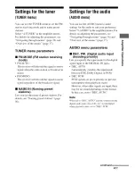
Page 40: ...justing the parameters see Navigating through menus page 36 and Overview of the menus page 37 SUR menu parameters S F SELCT Sound field selection Lets you select the sound fieM you want For details see Enjoying Surround Sound page 46 Note The receiver lets you apply the last selected sound field to an input whenever it is selected Sound Field Link For example if you select HALL for the SA CD CD in...

Page 41: ...56 Settingsfortheaudio AUDIO menu You can use the AUDIO menu to make settings for the audio to suit your preference Select 5 AUDIO in the amplifier menus For details on adjusting the parameters see Navigating through menus page 36 and Overview of the menus page 37 AUDIO menu parameters DEC PRI Digital audio input decoding priority Lets you specify the input mode for the digital signal input to the...

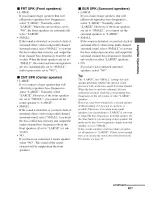
Page 42: ...This parameter is valid onlywhen you use a sound field selected with the 2CHor A F D buttons This parameter is not valid when PCM 96 kHz or DTS 2048 signals are input ANALOG DIRECTlm ction is selected NAME IN Naming inputs Lets you set the name of inputs For details see Naming inputs page 59 Settingsforthesystem SYSTEMmenu You can use the SYSTEM menu to set the size and distance of the speakers co...

Page 43: ... speakers SUR SPK Surround speakers LARGE If you connect large speakers that will effectively reproduce bass frequencies select LARGE Normally select LARGE However if the front speakers are set to SMALL you cannot set the surround speakers to LARGE SMALL If the sound is distorted or you feel a lack of surround effects when using multi channel _ surround sound select SMALL to activate t the bass re...

Page 44: ... not possible to set the center speaker lurther than the front speakers Also the center speaker canuot be set more than 1 5 meter 5 feet closer from the front speakers Likewise the surround speakers can not be set l_Lrther away li om the listeniug position than the lhont speakers And they can be no more than 4 5 meter 15 lhet closer This is because incorrect speaker placement is not conducive to t...

Page 45: ...vertheless each listening euviroumm_t has many variables such as wall reflections and you may obtain better results using BEHD HI if your speakers are located high above the listeniug positiuu even if they are located to the immediate lefl and right Thereli re although it may result in a setting contrary to the above explanatiuu we recommend that yuu playback multi chamlel surround eucuded softwar...

Page 46: ...ge 28 Enjoying DolbyDigital andDTSSurround sound AUTO FORMAT DIRECT The Auto Format Direct A F D mode allows yon to listen to higher fidelity sound and select the decoding mode for listening to a 2 channel stereo sound as nmlti channel sound Press A F D repeatedly to select the sound field you want For details see Types of A F D mode page 47 46 G8 ...

Page 47: ...nel lunnat is decoded into 4 I channels 5 channel Performs Dolby Pro Logic II Movie mode Dolby Pro Logic PRO LOGIC I1 MOVIE lI PLII MV decoding This setting is ideal li r movies encoded in Dolby Surround In addition this mode can reproduce sound in 5 1 channel lbr watching videos of overdubbed or old movies PRO LOGIC I1 MUSIC 5 channel Perlorms Dolby Pro Logic II Music mode PLII MSI decoding This ...

Page 48: ...ls with a sampling frequency of more than 48 kHz is input Selectinga pre programmed sound field You can take advantage of surround sound simply by selecting one of the receiver s pre programmed sound fields They bring the exciting and powerfld sound of movie theaters and concert halls into your home 2CH A ED Press MOVIE repeatedly to select a sound field for movies or press MUSIC repeatedly to sel...

Page 49: ...ndtrack m Music HALL HALL Reproduces the acoustics of a classical concert hall _ O JAZZ CLUB JAZZ Reproduces Ihe acoustics of a jazz club _ LIVE CONCERT Reproduces the acouslics of a 300 seal live house _ CONCERTI Headphone HEADPHONE 2CH This mode is selected automatically if you use headphones __ HP 2CH when 2 channel mode page 5 I A F D lnode page 47 is selected Slandard 2 channel stereo sources...

Page 50: ...ation Reproduces the type of reverberation fonnd in theaters The CINEMA STUDIO EX modes integrate these three elements simultaneously Notes The efli cts provided h_ the virtu 1 speakers may cause increased noise in the playback signah When listening with sound fields that employ the virtual speakers you will not be able to hear any sound coming directly from the surround speakers This limction doe...

Page 51: ...TO page 47 Listening to thesound withoutanyadjustment ANALOG DIRECT You can switch the audio of the selected input to two channel analog input This flmction enables you to enjoy high quality analog sources When using this function only the volume and front speaker balance can be adjusted Soundfield 1 2 buttons 2 Turn INPUT SELECTOR on the receiver to select the input you want to listen to in analo...

Page 52: ...Listeningto FM AMradio You can listen to FM and AM broadcasts through the built in tuner Before operation make sure you have connected the FM and AM antennas aerials to the receiver page 25 Tip The tuning scale lot direct tuning differs depending on the area code as shown irathe lolIowing table For details on area codes see page 3 Area code FM AM U CA 100 kHz IO kHz CEL CEK AU TW 50 kHz 9 kHz KR T...

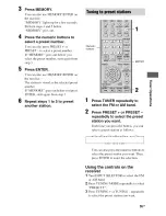
Page 53: ...G to scan from low to high press TUNING to scan from high to low The receiver stops scanning whenever a station is received Using the controls on the receiver 1 Turn INPUT SELECTOR to select tile FM or AM band 2 Press TUNING MODE repeatedly to select AUTO T 3 Press TUNING or TUNING 1 Press TUNER repeatedly to select the FM or AM band You can also use INPUT SELECTOR on the receiver 2 Press D TUNING...

Page 54: ...used in your area Presettingradiostations You can preset up to 30 FM stations and 30 AM stations Then you can easily tune in the stations you often listen to 4 3 5 PRESET 2 Press TUNER repeatedly to select the FM or AM band You c m also lase INPUT SELECTOR m the receiver Tune in the station that you want to preset using Automatic Tuning page 53 or Direct Tuning page 53 Switch the FM reception mode...

Page 55: ...ORY goes out before you press ENTER start again from step 3 Repeat steps 1 to 5 to preset another station Numeric buttons 1 2 Press TUNER repeatedly to select the FM or AM band Press PRESET or PRESET repeatedly to select the preset station you want Each time you press tile button you can select a preset station as follows You can also press the nmneric buttons to select the preset station you want...

Page 56: ...reate an index name 1 Use 141_ 1 to create an index name Press 1 to select a character then press _ 1 _to move the cursor to the next position If you made a mistake Press _ _ until tile character you want to change flashes then press 14 to select the correct character Tip Youcan select the character type as lollows hy pressing _ _ Alphabet upper case _ Numbers _ Symbols 2 Press _ The entered name ...

Page 57: ... repeatedly on the receiver Each time you press the button RDS information on the display changes cyclically as follows Program Service name _ Frequency Program Type indication a _ Radio Text indication b _ Current Time indication in 24 hour system mode _ Sound field currently applied a Type of program being broadcast b Tcxt messages sent by the RDS station Notes If there is an emergency announcem...

Page 58: ...the popular music of the country or region OLDIES Programs featuring oldies music FOLK M Folk music programs DOCUMENT Investigative Ii atures NONE Any programs not defined above Switchingbetween digitalandanalogaudio INPUT MODE When you connect components to both digital and analog audio input jacks SAT on the receiver you can fix the audio input mode 1 Turn INPUT SELECTOR on the receiver to selec...

Page 59: ...tc by changing the information on the display Be sure to use the buttons on the receiver for this operation Press DISPLAY repeatedly Each time yon press the button the display changes cyclically as follows All inputs except the FM and AM band Index name of the input a _ Selected input Sound field currently applied FM and AM band Program Service name b or preset station name a _ Freqnency _ Program...

Page 60: ... is _ pressed Tip To check the remaining time beh_re the receiver turns ofl press SLEEP The rmnaining lime appears on the display If you press SLEEP again the sleep timer will be canceled Recording usingthe receiver 4 Prepare the playback component for playing For example insertthe video tape you want to copy into the VCR Prepare the recording component Insert a bhmk video tape etc into tile recor...

Page 61: ... a 2 DVD player DVD recorder 3 command mode DVD 1 b DVD recorder 4 command mode DVD3 b CD player 5 Euro Digital Satellite Receiver 6 DVR Digital CATV terminal 7 DSS Digital Satellite Receiver 8 Blu ray disc player 9 command mode BDI c Blu ray disc recorder 0110 command mode BD3 c TV 1 Not assigned ENTER MEMORY a Sony VCRs are operaled wifll a VTR 2 or VTR 3 r setting which corresponds to 8 mm and ...

Page 62: ... Logic Audio processing technology developed by Dolby Laboratories Inc Center and mono surround int_rmation is matrixed into two stereo channels When reproduced audio is decoded and output in 4 channel surround sound This is the most connnon audio processing method for DVD video DTS Digital Surround Digital audio encoding decoding technology I_r theaters developed by DTS Inc It compresses audio Je...

Page 63: ...ure of the top side and bottom rises considerably To avoid burning yoursel do not touch the cabinet On placement Place the receiver in a location with adequate ventilation to prevent heat buildup and prolong the life of the receiver Do not place the receiver near heat sources or in a place subject to direct sunlight excessive dust or mechanical shock Do not place anything on top of the cabinet tha...

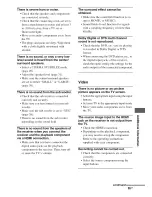
Page 64: ...iver and the component There is no sound from one of the front speakers Connect a pair of headphones to the PHONES jack to verify that sound is output from the headphones If only one channel is output from the headphones the component may not be connected to the receiver correctly Check that all the cords are fully inserted into the jacks on both the receiver and the component If both channels are...

Page 65: ...cted tile digital audio jacks on the playback component to the receiver Then turn off or mute the TV s volume The surround effect cannot be obtained Make sure the sound fieM function is on press MOVIE or MUSIC Sound fieMs do not function for signals with a sampling frequency of more than 48 kHz Dolby Digital or DTS multi channel sound is not reproduced Check that the DVD etc you are playing is rec...

Page 66: ...e sure that you are tuned to an FM RDS station Select a stronger FM station The RDS information that you want does not appear Contact tile radio station and find out whether they actually provide the service in question If so the service may be temporarily Ol ltof order _ Models of area code CEL CEK only Remote commander The remote does not function Point the remote at tile remote sensor on the re...

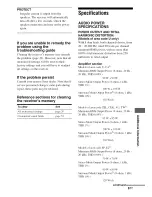
Page 67: ...R SPECIFICATIONS POWER OUTPUT AND TOTAL HARMONIC DISTORTION Models of area code U only With 8 ohm loads both channels dri_ en from 20 20 000 Hz rated 90 watts per channel mininmm RMS power with no more than 0 09 total harmonic distortion from 250 milliwatts to rated output Amplifier section Models of area code U CA Mininmm RMS Output Power 8 ohms 20 Hz 20 kHz THD 0 09r7_ 90 W 90 W Stereo Mode Outp...

Page 68: ...e source there may be no sound output 3 Measured under the following conditions Area code Power requirements KR TH6 220 V AC 50 Hz Frequency response Analog Inputs Analog Digital Coaxial Digital Optical Outputs Analog AUDIO OUT SUB WOOFER Tone Gain levels lC Hz 70 kHz 0 5 2 dB with sound field and tone bypassed Sensitivity 500 mV 50 kohms S N4 96 dB A 500 mV5 hnpedance 75 ohms S N 100dB CA 20 kHz ...

Page 69: ...z AU 240 V AC 5 1Hz KR TH6 220 230 V AC 50160 Hz E2 1201220 240 V AC 5 160Hz TW 110 V AC 60 Hz SP 230 240 V AC 5 60 Hz Power COllStllllptiol Area code Power consumption U EL CEK AU 22 W KR E2 CA 300 VA TH6 SP 200 W TW 500 W Power COllSUIllptiOll Dimensions w h d Mass Approx during standby mode 0 3 W Approx 430 5 x 157 5 x 309 mm 16 718 x 6 218 x 12 118 inches including pr _jecting parts and COlltn...

Page 70: ...Initial setup 26 INPUT MODE 58 M Menu A CAL 46 AUDIO 41 LEVEL 39 SUR 40 SYSTEM 42 TONE 40 TUNER 41 Muting 33 N Naming 56 59 R RDS 57 Recording onto a recording media 60 S Satellite tuner connecting 23 Selecting component 32 sound field 48 speaker system 27 Set top box connecting 23 Sleep Timer 60 Sound fields resetting 52 selecting 48 Speakers connecting 15 Super Audio CD player connecting 16 play...

Page 71: ... 289842911 1 Sony Corporation Printed in Malaysia http www sony net ...

Reviews: