background image

57

GB

C:\Documents and 
Settings\pc13\Desktop\JC060016_2680065111DG700_GB\2680065111\GB06ENJ_STR-DG700-
CEL.fm

masterpage: Right

STR-DG500

2-662-258-

12

 (1)

T

uner O

p

e

ratio

ns

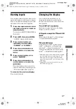
Resetting sound fields to 
the initial settings

Be sure to use the buttons on the receiver for 
this operation.

1

Press 

?

/

1

 to turn off the power.

2

While holding down 2CH, press 

?

/

1

.

“S.F. CLR.” appears on the display and all 
sound fields are reset to their initial 
setting.

Listening to FM/AM radio

You can listen to FM and AM broadcasts 
through the built-in tuner. Before operation, 
make sure you have connected the FM and 
AM antennas to the receiver (page 28).

Tip

The tuning scale for direct tuning differs depending 
on the area code as shown in the following table. For 
details on area codes, see page 2.

?/1

AUTO CAL MIC

SPEAKERS

(OFF/A/B/A+B)

PHONES

MEMORY/ 

ENTER

SUR BACK
DECODING

2CH

SLEEP

DIMMER

A.F.D.

MOVIE

MUSIC

MULTI CHANNEL DECODING

TUNING MODE

DISPLAY

INPUT MODE

INPUT SELECTOR

TUNING

+

MULTI CH IN

DIRECT

MASTER VOLUME

VIDEO 3 IN/PORTABLE AV IN

VIDEO

L  AUDIO   R

DIGITAL(OPT)

1,2

2

Tuner Operations

Area code

FM 

AM

CEL, CEK, AU

50 kHz

9 kHz

GB01COV_STR-DG700-CEL.book  Page 57  Wednesday, February 15, 2006  4:11 PM

Summary of Contents for STR-DG700

Page 1: ...tings pc13 Desktop JC060016_2680065111DG700_GB 2680065111 GB01COV_STR DG700 CEL fm masterpage Right 2006 Sony Corporation 2 680 065 11 1 Multi Channel AV Receiver Operating Instructions STR DG700 GB01COV_STR DG700 CEL book Page 1 Wednesday February 15 2006 4 11 PM ...

Page 2: ...icense from Dolby Laboratories Dolby Pro Logic Surround EX and the double D symbol are trademarks of Dolby Laboratories DTS DTS ES Neo 6 and DTS 96 24 are trademarks of Digital Theater Systems Inc This receiver incorporates High Definition Multimedia Interface HDMITM technology HDMI the HDMI logo and High Definition Multimedia Interface are trademarks or registered trademarks of HDMI Licensing LLC...

Page 3: ...enu 46 Settings for the system SYSTEM menu 47 Calibrating the appropriate settings automatically A CAL menu 50 Enjoying Surround Sound Enjoying Dolby Digital and DTS Surround sound AUTO FORMAT DIRECT 51 Selecting a pre programmed sound field 53 Using only the front speakers 2CH STEREO 56 Listening to the sound without any adjustment ANALOG DIRECT 56 Resetting sound fields to the initial settings 5...

Page 4: ... TUNING MODE DISPLAY INPUT MODE INPUT SELECTOR TUNING MULTI CH IN DIRECT MASTER VOLUME VIDEO 3 IN PORTABLE AV IN VIDEO L AUDIO R DIGITAL OPT PUSH 1 5 2 6 8 q 4 3 9 7 qa qs wd qd qf wa ws qg qh qj qk ql w Name Function A 1 Press to turn the receiver on or off page 29 36 37 57 59 B SPEAKERS OFF A B A B Press to select OFF A B A B of the front speakers page 30 C TUNING MODE Press to select the tuning...

Page 5: ...ULTI CH IN jacks page 35 M INPUT SELECTOR Turn to select the input source to playback page 35 36 37 56 58 62 64 67 68 69 N MOVIE MUSIC Press to select sound fields MOVIE MUSIC page 53 O A F D Press to select A F D mode page 51 P 2CH Press to select 2CH STEREO mode page 56 57 Q SUR BACK DECODING Press to select the surround back decoding mode page 44 R SLEEP Press to activate the Sleep Timer functi...

Page 6: ...rmat disc be sure that you have made digital connections and that INPUT MODE is not set to ANALOG page 64 Name Function E PRO LOGIC II IIx Lights up when the receiver applies Pro Logic processing to 2 channel signals in order to output the center and surround channel signals PRO LOGIC II lights up when the Pro Logic II Movie Music Game decoder is activated PRO LOGIC IIx lights up when the Pro Logi...

Page 7: ...UT MODE is set to AUTO and the source signal is a digital signal being input through the COAXIAL jack or when INPUT MODE is set to COAX IN page 64 P OPT Lights up when INPUT MODE is set to AUTO and the source signal is a digital signal being input through the OPTICAL jack or when INPUT MODE is set to OPT IN page 64 Q SLEEP Lights up when the sleep timer is activated page 68 Name Function R Playbac...

Page 8: ... MONITOR OUT COMPONENT VIDEO Y ASSIGNABLE PB CB B Y PR CR R Y 2 3 4 6 5 1 A DIGITAL INPUT OUTPUT section OPTICAL IN OUT jack Connects to a DVD player etc The COAXIAL jack provides a better quality of loud sound page16 23 25 COAXIAL IN jack HDMI IN MONITOR OUT jack Connects to a DVD player or asatellite tuner The image and the sound are output to a TV or a projector page 26 B VIDEO AUDIO INPUT OUTP...

Page 9: ...hich has an analog audio jack for 5 1 channel sound page 18 PRE OUT jack Connects to an external power amplifier F ANTENNA section FM ANTENNA Connects to the FM wire antenna supplied with this receiver page 28 AM ANTENNA Connects to the AM loop antenna supplied with this receiver page 28 White L Red R White L Red R Black White L Red R Remote commander SYSTEM STANDBY TUNING DISC SKIP MUTING TOP MEN...

Page 10: ... 3 VCR VTR mode 1 DVD DVD player MD TAPE MD deck SA CD CD Super Audio CD CD player TUNER Built in tuner AUX Not assigned Name Function E D TUNING Press to enter direct tuning mode F AUTO CAL Press to activate the Auto Calibration function G Numeric buttons number 5a Press to preset tune to preset stations select track numbers of the CD player VCD player LD player DVD player MD deck DAT deck or tap...

Page 11: ...o adjust the TV volume level MASTER VOL Press to adjust the volume level of all speakers at the same time MUTING Press to mute the sound To mute the sound of the TV press TV Z and then press MUTING Name Function P Press to skip tracks of the VCR CD player VCD player LD player DVD player MD deck DAT deck tape deck Blu ray disc recorder PSX DVD VIDEO COMBO or DVD HDD COMBO REPLAY ADVANCE Press to re...

Page 12: ...mation displayed on the TV screen of the VCR VCD player LD player DVD player CD player MD deck Blu ray disc recorder PSX satellite tuner DVD VIDEO COMBO or DVD HDD COMBO To select information of Sony TV press TV Z and then press DISPLAY T CLEAR Press to clear a mistake when you press the incorrect numeric button return to continuous playback etc of the Blu ray disc recorder PSX satellite tuner DVD...

Page 13: ...ront speaker L BFront speaker R CCenter speaker DSurround speaker L ESurround speaker R GSub woofer You can enjoy high fidelity reproduction of DVD software recorded sound in the Surround EX format if you connect one additional surround back speaker 6 1 channel see Using the surround back decoding mode on page 44 Example of a 6 1 channel speaker system configuration AFront speaker L BFront speaker...

Page 14: ...watching movies If the auto standby function is set to ON it turns to standby mode automatically based on the level of the input signal to a sub woofer then sound may not be output HDMI DVD IN ASSIGNABLE VIDEO 2 IN MONITOR OUT L R AUDIO IN VIDEO IN DVD AUDIO IN S VIDEO IN VIDEO IN VIDEO 2 AUDIO IN S VIDEO IN VIDEO OUT VIDEO 1 AUDIO OUT S VIDEO OUT VIDEO IN S VIDEO IN L R MD TAPE OUT L R IN VIDEO O...

Page 15: ...MULTI CH OUTPUT jacks etc This connection is used to output audio decoded by the component s internal multi channel decoder through this receiver c Model equipped only with AUDIO OUT L R jacks etc The sound quality depends on the connecting jack Refer to the illustration that follows Select the connection according to the jacks of your components How to hook up your components Component With Page ...

Page 16: ...EO 2 AUDIO IN S VIDEO IN VIDEO OUT VIDEO 1 AUDIO OUT S VIDEO OUT VIDEO IN S VIDEO IN L R AUX IN L R VIDEO OUT S VIDEO OUT MONITOR SUB WOOFER SURROUND PRE OUT L R SURROUND SUB WOOFER CENTER FRONT L R MULTI CH IN IN MD TAPE OUT L R IN DIGITAL VIDEO 1 IN VIDEO 2 IN MD TAPE IN MD TAPE OUT DVD IN COAXIAL OPTICAL DVD IN VIDEO 2 IN MONITOR OUT COMPONENT VIDEO Y ASSIGNABLE PB CB B Y PR CR R Y SA CD CD IN ...

Page 17: ...lied with the Super Audio CD player You cannot make digital recordings if you make only analog connections Likewise you cannot make analog recordings if you make only digital connections To make digital recordings make digital connections and to make analog recordings make analog connections You cannot make digital recordings of a Super Audio CD disc Use the analog jack for recording in this case ...

Page 18: ...ing components with multi channel output jacks DIGITAL VIDEO 1 IN VIDEO 2 IN MD TAPE IN MD TAPE OUT DVD IN SA CD CD IN COAXIAL OPTICAL ANTENNA AM HDMI DVD IN ASSIGNABLE VIDEO 2 IN MONITOR OUT L R AUDIO IN VIDEO IN DVD AUDIO IN S VIDEO IN VIDEO IN VIDEO 2 AUDIO IN S VIDEO IN VIDEO OUT VIDEO 1 AUDIO OUT S VIDEO OUT VIDEO IN S VIDEO IN L R SA CD CD MD TAPE OUT L R IN IN AUX IN L R VIDEO OUT S VIDEO O...

Page 19: ... IN SA CD CD IN COAXIAL OPTICAL ANTENNA AM HDMI DVD IN ASSIGNABLE VIDEO 2 IN MONITOR OUT L R AUDIO IN VIDEO IN DVD AUDIO IN S VIDEO IN VIDEO IN VIDEO 2 AUDIO IN S VIDEO IN VIDEO OUT VIDEO 1 AUDIO OUT S VIDEO OUT VIDEO IN S VIDEO IN L R VIDEO OUT S VIDEO OUT MONITOR SURROUND BACK CENTER SURROUND FRONT A R R L L SPEAKERS SUB WOOFER SURROUND PRE OUT L R SURROUND SUB WOOFER CENTER FRONT L R MULTI CH I...

Page 20: ...onnect each component After hooking up all your components proceed to 4 Connecting the antennas page 28 Component to be connected The image quality depends on the connecting jack Refer to the illustration that follows Select the connection according to the jacks on your components How to hook up your components Component Page TV monitor 22 DVD player DVD recorder 23 Satellite tuner 25 With HDMI ja...

Page 21: ...be output from the S video or component video MONITOR OUT jack S video signals can also be output as component video signals and this upconverted video signals can only be output from the component video MONITOR OUT jack Note on converting video signals When video signals from a VCR etc are converted on this receiver and then output to your TV depending on the status of the video signal output the...

Page 22: ...p You can watch the selected input image when you connect the MONITOR OUT jack to a TV monitor Hooking up a TV monitor DIGITAL VIDEO 1 IN VIDEO 2 IN MD TAPE IN MD TAPE OUT DVD IN SA CD CD IN COAXIAL OPTICAL ANTENNA AM HDMI DVD IN ASSIGNABLE VIDEO 2 IN MONITOR OUT L R AUDIO IN VIDEO IN DVD AUDIO IN S VIDEO IN VIDEO IN VIDEO 2 AUDIO IN S VIDEO IN VIDEO OUT VIDEO 1 AUDIO OUT S VIDEO OUT VIDEO IN S VI...

Page 23: ...tal audio jacks are compatible with 32 kHz 44 1 kHz 48 kHz and 96 kHz sampling frequencies Hooking up a DVD player DVD recorder ANTENNA AM HDMI DVD IN ASSIGNABLE VIDEO 2 IN MONITOR OUT L R AUDIO IN VIDEO IN VIDEO 2 AUDIO IN S VIDEO IN VIDEO OUT VIDEO 1 AUDIO OUT S VIDEO OUT VIDEO IN S VIDEO IN L R SA CD CD MD TAPE OUT L R IN IN AUX IN L R VIDEO OUT S VIDEO OUT MONITOR SURROUND BACK CENTER SURROUND...

Page 24: ...IN MD TAPE IN MD TAPE OUT DVD IN SA CD CD IN COAXIAL OPTICAL ANTENNA AM HDMI DVD IN VIDEO 2 IN MONITOR OUT L R AUDIO IN VIDEO 2 AUDIO IN S VIDEO IN VIDEO 1 S VIDEO OUT VIDEO IN SA CD CD MD TAPE OUT L R IN IN AUX IN L R VIDEO OUT MONITOR SURROUND BACK CENTER SURROUND FRONT A R R L L SPEAKERS SUB WOOFER SURROUND PRE OUT L R SUB WOOFER CENTER R VIDEO IN DVD AUDIO IN S VIDEO IN DVD IN VIDEO 2 IN MONIT...

Page 25: ...ner ANTENNA AM DVD IN ASSIGNABLE L R AUDIO IN VIDEO IN DVD AUDIO IN S VIDEO IN VIDEO 1 AUDIO OUT S VIDEO OUT VIDEO IN S VIDEO IN L SA CD CD MD TAPE OUT L R IN IN AUX IN L R VIDEO OUT S VIDEO OUT MONITOR SURROUND BACK CENTER SURROUND FRONT A R R L L SPEAKERS SUB WOOFER SURROUND PRE OUT L R SURROUND SUB WOOFER CENTER FRONT L R MULTI CH IN VIDEO IN S VIDEO IN DIGITAL VIDEO 1 IN VIDEO 2 IN MD TAPE IN ...

Page 26: ... transmitted Audio signals sampling frequency bit length etc transmitted from a HDMI jack may be restricted by the connected component Check the setup of the connected component if the image is poor or the sound does not come out of a component connected via the HDMI cable Refer to the operating instructions of each component connected for details Hooking up components with HDMI jacks DIGITAL VIDE...

Page 27: ...VIDEO IN DVD AUDIO IN S VIDEO IN VIDEO 2 AUDIO IN S VIDEO OUT VIDEO IN S VIDEO IN L R SA CD CD MD TAPE OUT L R IN IN AUX IN L R VIDEO OUT S VIDEO OUT MONITOR SURROUND BACK CENTER SURROUND FRONT A R R L L SPEAKERS SUB WOOFER SURROUND PRE OUT L R SURROUND SUB WOOFER CENTER FRONT L R MULTI CH IN DVD IN VIDEO 2 IN MONITOR OUT COMPONENT VIDEO Y ASSIGNABLE PB CB B Y PR CR R Y VIDEO 3 IN PORTABLE AV IN D...

Page 28: ... as possible DIGITAL VIDEO 1 IN VIDEO 2 IN MD TAPE IN MD TAPE OUT DVD IN SA CD CD IN COAXIAL OPTICAL HDMI DVD IN ASSIGNABLE VIDEO 2 IN MONITOR OUT L R AUDIO IN VIDEO IN DVD AUDIO IN S VIDEO IN VIDEO IN VIDEO 2 AUDIO IN S VIDEO IN VIDEO OUT VIDEO 1 AUDIO OUT S VIDEO OUT VIDEO IN S VIDEO IN L R SA CD CD MD TAPE OUT L R IN IN AUX IN L R VIDEO OUT S VIDEO OUT MONITOR SURROUND BACK CENTER SURROUND FRON...

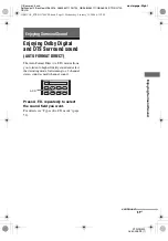
Page 29: ...lowing procedure This procedure can also be used to return settings you have made to their factory defaults Be sure to use the buttons on the receiver for this operation 1 Press 1 to turn off the receiver 2 Hold down 1 for 5 seconds PUSH and ENTER appears on the display alternately 3 Press MEMORY ENTER After CLEARING appears on the display for a while CLEARED appears The following items are reset ...

Page 30: ...eries with new ones 6 Selecting the speaker system You can select the front speakers you want to drive Be sure to use the buttons on the receiver for this operation Press SPEAKERS OFF A B A B repeatedly to select the front speaker system you want to drive To turn off the speaker output press SPEAKERS OFF A B A B repeatedly until the SP A and SP B indicators on the display do not light up Inserting...

Page 31: ...phone to a tripod not supplied and place the tripod at your listening position Be sure to remove any obstacles in the path between the optimizer microphone and the speakers When you face the speaker towards the optimizer microphone you will get a more accurate measurement Before you perform Auto Calibration 1 AUTO CAL MIC SPEAKERS OFF A B A B PHONES MEMORY ENTER SUR BACK DECODING 2CH SLEEP DIMMER ...

Page 32: ...an error is detected during Auto Calibration an error code will appear on the display cyclically after each measurement process as follows Error code t blank display t error code t blank display a t PUSH t blank display t ENTER a Appears when there are more than one error code To rectify the error 1 Record down the error code 2 Press AMP to light up the button then press the control button 3 Press...

Page 33: ...speaker distance page 48 g For details refer Surround back speaker distance page 49 ERROR 23 Surround back speaker is detected but surround speakers are not connected Be sure to connect the surround speakers Error code Explanation Remedies Warning code Explanation Solution WARN 40 The environment is noisy Make sure the environment is quiet during Auto Calibration WARN 60 The front speaker balance ...

Page 34: ...put from each speaker in sequence as follows Front left t Center t Front right t Surround right t Surround back t Surround left t Sub woofer 6 Adjust the speaker levels and balance using the LEVEL menu so that the level of the test tone sounds the same from each speaker For details see Adjusting the level LEVEL menu page 42 Tips To adjust the level of all speakers at the same time press MASTER VOL...

Page 35: ...you turn off the receiver be sure to turn down the volume level Playback SYSTEM STANDBY TUNING DISC SKIP MUTING TOP MENU MENU F1 TV VIDEO WIDE F2 TV VOL MASTER VOL TV CH PRESET TUNING DISPLAY TOOLS RETURN EXIT AMP REPLAY ADVANCE VIDEO 1 VIDEO 2 DVD VIDEO 3 MD TAPE SA CD CD AUX MULTI CH 2CH A F D MOVIE MUSIC SLEEP FM MODE D TUNING AUTO CAL TUNER MEMORY m M x X B B V v MENU H 3 CLEAR 10 DVD 1 2 4 5 ...

Page 36: ...T UP 1 MEMORY m M x X B B V v MENU H 3 CLEAR 10 DVD 1 2 4 5 7 8 6 9 ENTER 0 10 5 5 3 2 3 Notes The operation is described for a Sony Super Audio CD player Refer to the operating instructions supplied with the Super Audio CD player or CD player Tips You can select the sound field to suit the music Refer to page 53 for details Recommended sound fields Classical HALL Jazz JAZZ Live concert CONCERT Yo...

Page 37: ...upplied with the TV and DVD player Check the following if you cannot listen to multi channel sound Be sure the sound source corresponds to the multi channel format the MULTI CHANNEL DECODING lamp on the front panel lights up during playback Be sure this receiver is connected to the DVD player via a digital connection Be sure the digital audio output of the DVD player is set up properly Tips Select...

Page 38: ...he menu 4 Press control button V v repeatedly to select the parameter you want to adjust 5 Press the control button or control button b to enter the parameter 6 Press control button V v repeatedly to select the setting you want The setting is entered automatically To return to the previous display Press control button B To exit the menu Press MENU Note Some parameters and settings may appear dimme...

Page 39: ...R R 10 dB 1 dB step SUR R 0 dB Surround back speaker level SB LVL SB 10 dB to SB 10 dB 1 dB step SB 0 dB Sub woofer level SW LVL SW 10 dB to SW 10 dB 1 dB step SW 0 dB Dynamic range compressora D RANGE COMP OFF COMP STD COMP MAX COMP OFF EQ 43 2 EQ Equalizera EQ EQ ON EQ OFF EQ OFF Front speaker bass level BASS LVL BASS 6 dB to BASS 6 dB 1 dB step BASS 0 dB Front speaker treble level TRE LVL TRE 6...

Page 40: ... 2 3 DEC PCM for DVD MD TAPE SA CD CD Digital broadcast language selectiona DUAL DUAL M S DUAL M DUAL S DUAL M S DUAL M A V Synca A V SYNC A V SYNC 0 A V SYNC 20 A V SYNC 0 Naming inputsa NAME IN VIDEO 46 6 VIDEO Component video assigna COMP V A DVD VD1 DVD VD3 DVD DVD DVD MD DVD CD DVD AUX VD2 VD1 VD2 VD2 VD2 VD3 VD2 MD VD2 CD VD2 AUX DVD DVD for DVD VD2 VD2 for VIDEO 2 HDMI assigna HDMI A DVD VD...

Page 41: ... speaker distancea CNT DIST DIST xx m between front speaker distance and 1 5 m 0 1 m step DIST 3 0 m Surround left speaker distancea SL DIST DIST xx m between front speaker distance and 4 5 m 0 1 m step DIST 3 0 m Surround right speaker distancea SR DIST DIST xx m between front speaker distance and 4 5 m 0 1 m step DIST 3 0 m Surround back speaker distancea SB DIST DIST xx m between front speaker ...

Page 42: ... LVL Surround right speaker level x SB LVL Surround back speaker level x SW LVL Sub woofer level x D RANGE Dynamic range compressor Lets you compress the dynamic range of the sound track This may be useful when you want to watch movies at low volumes late at night Dynamic range compression is possible with Dolby Digital sources only COMP OFF The dynamic range is not compressed COMP STD The dynamic...

Page 43: ... the amplifier menus For details on adjusting the parameters see Navigating through menus page 38 and Overview of the menus page 39 SUR menu parameters x S F SELCT Sound field selection Lets you select the sound field you want For details see Enjoying Surround Sound page 51 Note The receiver lets you apply the last selected sound field to an input whenever it is selected Sound Field Link For examp...

Page 44: ...signals d Software encoded with both 5 1 channel signals and an extension stream designed for returning those signals to 6 1 discrete channels Discrete 6 1 channel signals are DVD specific signals not used in movie theaters Notes There may be no sound from the surround back speaker in Dolby Digital EX mode Some discs have no Dolby Digital Surround EX flag even though the packages have Dolby Digita...

Page 45: ...eset stations For details see Naming preset stations page 62 Settings for the audio AUDIO menu You can use the AUDIO menu to make settings for the audio to suit your preference Select 5 AUDIO in the amplifier menus For details on adjusting the parameters see Navigating through menus page 38 and Overview of the menus page 39 AUDIO menu parameters x DEC PRI Digital audio input decoding priority Lets...

Page 46: ...n the audio output and visual display is minimized You can adjust from 0 0 ms to 20 200 ms in 1 10 ms steps x NAME IN Naming inputs Lets you set the name of inputs For details see Naming inputs page 67 Settings for the video VIDEO menu You can use the VIDEO menu to reassign the component video input to another input and to name inputs Select 6 VIDEO in the amplifier menus For details on adjusting ...

Page 47: ...om the sub woofer When the front speakers are set to SMALL the center surround and surround back speakers are also automatically set to SMALL unless previously set to NO x CNT SPK Center speaker LARGE If you connect a large speaker that will effectively reproduce bass frequencies select LARGE Normally select LARGE However if the front speakers are set to SMALL you cannot set the center speaker to ...

Page 48: ...fer set all speakers to LARGE If there is not enough bass you can use the equalizer to boost the bass levels For details see page 43 x FRT DIST Front speaker distance Lets you set the distance from your listening position to the front speakers A If both front speakers are not placed an equal distance from your listening position set the distance as the average distance between the front speakers x...

Page 49: ...tput of the sound from that speaker In other words the speaker will sound like it is further away For example setting the center speaker distance 1 2 meter closer than the actual speaker position will create a fairly realistic sensation of being inside the screen If you cannot obtain a satisfactory surround effect because the surround speakers are too close setting the surround speaker distance cl...

Page 50: ...ate left and right Therefore although it may result in a setting contrary to the above explanation we recommend that you playback multi channel surround encoded software and select the setting that provides a good sense of spaciousness and that best succeeds in forming a cohesive space between the surround sound from the surround speakers and the sound of the front speakers If you are not sure whi...

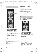
Page 51: ...Auto Format Direct A F D mode allows you to listen to higher fidelity sound and select the decoding mode for listening to a 2 channel stereo sound as multi channel sound Press A F D repeatedly to select the sound field you want For details see Types of A F D mode page 52 Enjoying Surround Sound MULTI CH 2CH A F D MOVIE MUSIC SLEEP FM MODE D TUNING AUTO CAL A F D continued GB01COV_STR DG700 CEL boo...

Page 52: ...MS 5 channel Performs Dolby Pro Logic II Music mode decoding This setting is ideal for normal stereo sources such as CDs PRO LOGIC II GAME PLII GM 5 channel Performs Dolby Pro Logic II Game mode decoding This setting is ideal for game softwares Dolby Pro Logic IIx PRO LOGIC IIx MOVIE PLIIX MV 6 channel Performs Dolby Pro Logic IIx Movie mode decoding This setting expands Dolby Pro Logic II Movie o...

Page 53: ... does not function for DTS format signals or for signals with a sampling frequency of more than 48 kHz Tip When a multi channel signal is input only Dolby Pro Logic IIx decoding is effective When you select decoding modes other than Dolby Pro Logic IIx multi channel sound being encoded is output Selecting a pre programmed sound field You can take advantage of surround sound simply by selecting one...

Page 54: ...featured in the soundtrack Music HALL HALL Reproduces the acoustics of a classical concert hall JAZZ CLUB JAZZ Reproduces the acoustics of a jazz club LIVE CONCERT CONCERT Reproduces the acoustics of a 300 seat live house Headphone HEADPHONE 2CH HP 2CH This mode is selected automatically if you use headphone when 2 channel mode page 56 A F D mode page 52 is selected Standard 2 channel stereo sourc...

Page 55: ...ema Studio Reverberation Reproduces the type of reverberation found in theaters The CINEMA STUDIO EX modes integrate these three elements simultaneously Notes The effects provided by the virtual speakers may cause increased noise in the playback signal When listening with sound fields that employ the virtual speakers you will not be able to hear any sound coming directly from the surround speakers...

Page 56: ...ECT You can switch the audio of the selected input to two channel analog input This function enables you to enjoy high quality analog sources When using this function only the volume and front speaker balance can be adjusted 1 Turn INPUT SELECTOR on the receiver to select the input you want to listen to in analog audio You can also use the input buttons on the remote 2 Press DIRECT on the receiver...

Page 57: ...M broadcasts through the built in tuner Before operation make sure you have connected the FM and AM antennas to the receiver page 28 Tip The tuning scale for direct tuning differs depending on the area code as shown in the following table For details on area codes see page 2 1 AUTO CAL MIC SPEAKERS OFF A B A B PHONES MEMORY ENTER SUR BACK DECODING 2CH SLEEP DIMMER A F D MOVIE MUSIC MULTI CHANNEL D...

Page 58: ...ODE repeatedly until the MONO indicator on the display do not light up Enter the frequency of a station directly by using the numeric buttons 1 Press TUNER repeatedly to select the FM or AM band You can also use INPUT SELECTOR on the receiver 2 Press D TUNING 3 Press the numeric buttons to enter the frequency Example 1 FM 102 50 MHz Select 1 b 0 b 2 b 5 b 0 Example 2 AM 1 350 kHz Select 1 b 3 b 5 ...

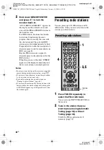
Page 59: ...on lets you store up to 30 FM and FM RDS stations in alphabetical order without redundancy Additionally it only stores the stations with the clearest signals If you want to store FM or AM stations one by one see Presetting radio stations page 60 Be sure to use the buttons on the receiver for this operation 1 Press 1 to turn off the receiver 1 AUTO CAL MIC SPEAKERS OFF A B A B PHONES MEMORY ENTER S...

Page 60: ...remote during autobetical operation except 1 If you move to another area repeat this procedure to store stations in your new area For details on tuning the stored stations see Tuning to preset stations page 61 If you move the antenna after storing stations with this procedure the stored settings may no longer be valid If this happens repeat this procedure to store the stations again Presetting rad...

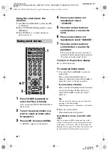
Page 61: ...ORY start again from step 3 6 Repeat steps 1 to 5 to preset another station 1 Press TUNER repeatedly to select the FM or AM band 2 Press PRESET or PRESET repeatedly to select the preset station you want Each time you press the button you can select a preset station as follows You can also press the numeric buttons to select the preset station you want Then press ENTER to enter the selection Tuning...

Page 62: ...o the previous display Press control button B To create an index name 1 Use control button V v B b to create an index name Press control button V v to select a character then press control button B b to move the cursor to the next position If you made a mistake Press control button B b until the character you want to change flashes then press control button V v to select the correct character Tip ...

Page 63: ...ly on the receiver Each time you press the button RDS information on the display changes cyclically as follows Program Service name t Frequency t Program Type indicationa t Radio Text indicationb t Current Time indication in 24 hour system mode t Sound field currently applied a Type of program being broadcast b Text messages sent by the RDS station Notes If there is an emergency announcement by go...

Page 64: ... not be set up depending on the input VARIED Other types of programs such as celebrity interviews panel games and comedy POP M Popular music programs ROCK M Rock music programs EASY M Easy Listening LIGHT M Instrumental vocal and choral music CLASSICS Performances of major orchestras chamber music opera etc OTHER M Music that does not fit into any categories above such as Rhythm Blues and Reggae W...

Page 65: ...ton V v repeatedly to select the input you want the component video input selected in step 6 to be reassigned to for example VIDEO 1 In this case select DVD VD1 When you press VIDEO 1 the image from the component connected to the VIDEO 1 jacks will be a component image The input you can reassign to varies for each component video input For details see Assignable inputs for component video input be...

Page 66: ...t the input you want the HDMI input selected in step 6 to be reassigned to for example VIDEO 1 In this case select DVD VD1 When you press VIDEO 1 the image from the component connected to the VIDEO 1 jacks will be a HDMI image The sound will be output from the TV speaker For details see Hooking up components with HDMI jacks page 26 The input you can reassign to varies for each HDMI input For detai...

Page 67: ... character Follow the procedure given in To create an index name page 62 To return to the previous display Press control button B Changing the display You can check the sound field etc by changing the information on the display Be sure to use the buttons on the receiver for this operation Press DISPLAY repeatedly Each time you press the button the display changes cyclically as follows All inputs e...

Page 68: ...d onto a MiniDisc or audio tape using the receiver See the operating instructions supplied with your MD deck or tape deck 1 Press one of the input buttons to select the playback component You can also use INPUT SELECTOR on the receiver 2 Prepare the playback component for playing For example insert a CD into the CD player 3 Prepare the recording component Insert a blank MD or tape into the recordi...

Page 69: ...eviously used input are output Programming the remote You can program the remote to control non Sony components by changing the code Once the control signals have been memorized you can use those components as part of your system Furthermore you can also program the remote for Sony components that the remote is unable to control Note that the remote can only control components that accept infrared...

Page 70: ...step 1 Notes The indicator turns off while a valid button is pressed In step 2 if several input buttons are pressed only the last pressed button is valid In step 2 if you press TUNER you can only program the button to control a tuner page 74 In step 3 if an input button is pressed the new input is selected and the programming procedure returns to the beginning of step 3 For the numeric codes only ...

Page 71: ... SONY 301 DENON 302 JVC 303 KENWOOD 304 Maker Code s SONY 201 202 DENON 204 205 KENWOOD 206 207 208 209 NAKAMICHI 210 PANASONIC 216 PHILIPS 211 212 PIONEER 213 214 TECHNICS 215 216 YAMAHA 217 218 Maker Code s SONY 601 602 603 PIONEER 606 Maker Code s SONY 605 Maker Code s SONY 701 702 703 704 705 706 AIWA 710 750 757 758 AKAI 707 708 709 759 BLAUPUNKT 740 EMERSON 711 712 713 714 715 716 750 FISHER...

Page 72: ...503 AOC 503 CENTURION 566 CORONADO 517 CURTIS MATHES 503 551 566 567 DAYTRON 517 566 DAEWOO 504 505 506 507 515 544 FISHER 508 545 FUNAI 548 FUJITSU 528 GOLDSTAR LG 503 512 515 517 534 544 556 568 GRUNDIG 511 533 534 HITACHI 513 514 515 544 557 503 519 517 571 ITT NOKIA 521 522 J C PENNY 503 510 566 JVC 516 552 KMC 517 MAGNAVOX 503 518 544 515 517 566 MARANTZ 527 MITSUBISHI MGA 503 519 527 544 566...

Page 73: ...566 ZENITH 542 543 567 GE 509 510 503 544 LOEWE 515 534 556 Maker Code s Maker Code s SONY 801 802 803 804 824 825 865 AMSTRAD 845 846 BskyB 862 GENERAL ELECTRIC GE 866 GRUNDIG 859 860 HUMAX 846 847 THOMSON 857 861 864 PACE 848 849 850 852 862 863 864 PANASONIC 818 855 PHILIPS 856 857 858 859 860 864 874 NOKIA 851 853 854 864 RCA PROSCAN 866 871 BITA HITACHI 868 HUGHES 867 JVC Echostar Dish Networ...

Page 74: ...together x Dolby Digital Digital audio encoding decoding technology developed by Dolby Laboratories Inc It consists of front left right center surround left right and sub woofer channels It is a designated audio standard for DVD video and also known as 5 1ch surround Since surround information is recorded and reproduced in stereo more realistic sound with fuller presence is delivered than with Dol...

Page 75: ...software x DTS Neo 6 This technology converts 2ch stereo recorded audio for 6 1ch playback There are two modes to select according to the playback source or your preference CINEMA for movies and MUSIC for stereo sources such as music x DTS Digital Surround Digital audio encoding decoding technology for theaters developed by Digital Theater Systems Inc It compresses audio less than Dolby Digital de...

Page 76: ... do not touch the cabinet On placement Place the receiver in a location with adequate ventilation to prevent heat buildup and prolong the life of the receiver Do not place the receiver near heat sources or in a place subject to direct sunlight excessive dust or mechanical shock Do not place anything on top of the cabinet that might block the ventilation holes and cause malfunctions Do not place th...

Page 77: ...ed into the jacks on both the receiver and the component There is no sound from one of the front speakers Connect a pair of headphones to the PHONES jack to verify that sound is output from the headphones If only one channel is output from the headphones the component may not be connected to the receiver correctly Check that all the cords are fully inserted into the jacks on both the receiver and ...

Page 78: ...ge 54 Adjust the speaker level page 34 Make sure the center surround speakers are set to either SMALL or LARGE page 41 Make sure the surround back speaker is set to YES page 41 There is no sound from the surround back speaker Some discs have no Dolby Digital Surround EX flag even though the packages have Dolby Digital Surround EX logos In this case select SB ON page 39 There is no sound from the s...

Page 79: ...tion Select a stronger FM station The RDS information that you want does not appear Contact the radio station and find out whether they actually provide the service in question If so the service may be temporarily out of order There is no picture or an unclear picture appears on the TV screen or monitor Select the appropriate input using the input buttons Set your TV to the appropriate input mode ...

Page 80: ...rning codes page 32 to solve the problem DEC EROR Appears when a signal the receiver cannot decode ex DTS CD is input and DEC PRI on the AUDIO menu is set to DEC PCM Set it to DEC AUTO page 40 PROTECT Irregular current is output from the speakers The receiver will automatically turn off after a few seconds Check the speaker connection and turn on the power again If you are unable to remedy the pro...

Page 81: ...N 100 dB A 20 kHz LPF Outputs Analog AUDIO OUT Voltage 500 mV 10 kohms SUB WOOFER SURROUND Voltage 2 V 1 kohm Equalizer Gain levels 6 dB 1 dB step 3 INPUT SHORT with sound field and equalizer bypassed 4 Weighted network input level FM tuner section Tuning range 87 5 108 0 MHz Intermediate frequency 10 7 MHz Useable sensitivity 11 2 dBf 1 µV 75 ohms S N Mono Stereo 76 dB 70 dB Harmonic distortion a...

Page 82: ... Approx 8 5 kg Supplied accessories FM wire antenna 1 AM loop antenna 1 Remote commander RM AAP011 1 R6 size AA batteries 2 Optimizer microphone ECM AC2 1 Design and specifications are subject to change without notice Area code Power requirements CEL CEK 230 V AC 50 60 Hz AU 240 V AC 50 Hz Area code Power consumption CEL CEK AU 220 W Area code AC outlets CEL CEK AU 1 switched 100 W 0 4 A MAX For d...

Page 83: ...20 HDMI ASSIGN 66 I Initial setup 29 INPUT MODE 64 M MD deck connecting 15 Menu A CAL 50 AUDIO 45 EQ 43 LEVEL 42 SUR 43 SYSTEM 47 TUNER 45 VIDEO 46 Muting 35 N Naming 62 67 R RDS 63 Recording onto a MiniDisc or audio tape 68 onto a recording media 69 S Satellite tuner hooking up 20 Selecting component 35 sound field 53 speaker system 30 Sleep Timer 68 Sound fields resetting 57 selecting 53 Speaker...

Page 84: ...s and Settings pc13 Desktop JC060016_2680065111DG700_GB 2680065111 GB08BKC_STR DG700 CEL fm Sony Corporation Printed in Malaysia model name1 STR DG500 2 662 258 12 1 GB01COV_STR DG700 CEL book Page 84 Wednesday February 15 2006 4 11 PM ...

Reviews: