background image

44

GB

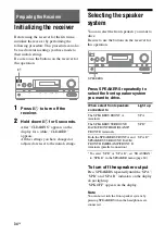
You can enter a name of up to 8 characters for 
inputs (except TUNER) and display it on the 
receiver’s display.
This is convenient for labeling the jacks with 
the names of the connected components.

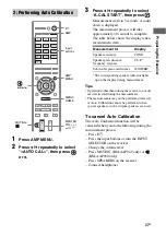
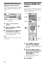
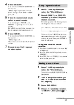
1

Press one of the input buttons 
to select the input you want to 
create an index name for.

You can also use INPUT SELECTOR on 
the receiver.

2

Press AMP MENU.

3

Press 

V

/

v

 repeatedly to select 

“<SYSTEM>”, then press 

 or 

b

.

4

Press 

V

/

v

 repeatedly


to select 

“NAME IN”, then press 

 or 

b

.

The cursor flashes and you can select a 
character.

5

Press 

V

/

v

 to select a character, 

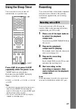
then press

 B

/

b

 to move the 

cursor to the next position. 

If you made a mistake

Press 

B

/

b

 until the character you want to 

change flashes, then press 

V

/

v

 to select 

the correct character.

Tips

• You can select the character type as follows 

by pressing 

V

/

v

.


Alphabet (upper case) 

t

 Numbers 

t


Symbols

• To enter a blank space, press 

b

 without 

selecting a character.

6

Press .

The name you entered is registered.

Viewing information on 
the display

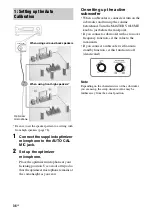
You can check the sound field, etc., by 
changing the information on the display.

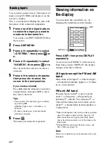
Press AMP, then press DISPLAY 
repeatedly.

You can also use DISPLAY on the receiver.
Each time you press DISPLAY, the display 
changes cyclically as follows:

All inputs except the FM and AM 
band

Index name of the input

a)


t

 Selected input 

t

 Sound field currently applied 

t

 Volume 

level 

t

 Stream info

FM and AM band

Program Service name

b)

 or preset station 

name

a)


t

 Frequency 

t

 Program Type 

indication

b)


t

 Radio Text indication

b)


t


Current Time indication (in 24-hour system 
mode)

b)


t

 Sound field currently applied 

t


Volume level

a)

Index name appears only when you have assigned 
one to the input or preset station (page 44, 49). 
Index name does not appear when only blank  
spaces have been entered, or it is the same as the 
input name.

b)

During 

RDS reception only (Models of area code 

CEL, CEK only) (page 50).

Note

Character or marks may not be displayed for some 
languages.

Naming inputs

DVD

VIDEO 1

HDMI 2

DMPORT

BD

SAT/

CATV

VIDEO 2

HDMI 3

HDMI 1

SA-CD/

CD

TUNER

TV

HDMI 4

DISPLAY

AMP

Summary of Contents for STR-DH810 - Audio Video Receiver

Page 1: ... 2010 Sony Corporation 4 168 075 11 1 Multi Channel AV Receiver Operating Instructions STR DH810 ...

Page 2: ...ing this product Model No Serial No This symbol is intended to alert the user to the presence of uninsulated dangerous voltage within the product s enclosure that may be of sufficient magnitude to constitute a risk of electric shock to persons This symbol is intended to alert the user to the presence of important operating and maintenance servicing instructions in the literature accompanying the a...

Page 3: ... into an outlet on a circuit different from that to which the receiver is connected Consult the dealer or an experienced radio TV technician for help CAUTION You are cautioned that any changes or modifications not expressly approved in this manual could void your authority to operate this equipment To reduce the risk of electric shock the speaker cord should be connected to the apparatus and the s...

Page 4: ...ttery this battery should be replaced by qualified service staff only To ensure that the battery will be treated properly hand over the product at end of life to the applicable collection point for the recycling of electrical and electronic equipment For all other batteries please view the section on how to remove the battery from the product safely Hand the battery over to the applicable collecti...

Page 5: ... 7 333 929 7 392 195 7 272 567 other U S and worldwide patents issued pending DTS is a registered trademark and the DTS logos Symbol DTS HD and DTS HD Master Audio are trademarks of DTS Inc 1996 2008 DTS Inc All Rights Reserved This receiver incorporates High Definition Multimedia Interface HDMITM technology HDMI the HDMI Logo and High Definition Multimedia Interface are trademarks or registered t...

Page 6: ...g FM AM radio stations 48 Using the Radio Data System RDS 50 Models of area code CEL CEK only Enjoying Surround Sound Selecting the sound field 51 Enjoying the surround effect at low volume levels NIGHT MODE 55 Resetting sound fields to the initial settings 55 BRAVIA Sync Features What is BRAVIA Sync 56 Preparing for the BRAVIA Sync 56 Playing back components with one touch operation One Touch Pla...

Page 7: ... Using the Remote Programming the remote 85 Clearing all the contents of the remote s memory 90 Additional Information Glossary 90 Precautions 93 Troubleshooting 95 Specifications 101 Index 103 Supplied accessories Operating instructions this manual Quick Setup Guide FM wire antenna aerial 1 AM loop antenna aerial 1 Remote commander 1 RM AAP049 Models of area code U2 only RM AAP050 Models of area ...

Page 8: ...signals from remote commander F DIMMER page 85 G MASTER VOLUME page 42 43 H MUTING page 43 I VIDEO 2 IN jacks page 30 J AUTO CAL MIC jack page 36 K DISPLAY page 44 L 2CH A DIRECT A F D MOVIE MUSIC page 51 M TUNING MODE TUNING MEMORY ENTER page 46 N INPUT MODE page 69 O PHONES jack page 95 P SPEAKERS page 34 Front panel 1 qg qa q 9 qs qd qf 6 5 7 8 4 1 3 2 qh ...

Page 9: ...l signal being input through the COAXIAL jack page 69 OPT Lights up when INPUT MODE is set to AUTO and the source signal is a digital signal being input through the OPTICAL jack page 69 Indicator and explanation D ARC Lights up when TV input is selected and the Audio Return Channel ARC signals are detected page 60 E Dolby Digital Surround indicators Lights up one of the respective indicators when ...

Page 10: ... Stereo broadcast O EQ Lights up when the equalizer is activated P D RANGE Lights up when dynamic range compression is activated page 77 Q Lights up when the disc being played back contains an LFE Low Frequency Effect channel and the LFE channel signal is actually being reproduced LFE Indicator and explanation R Playback channel indicators The letters L C R etc indicate the channels being played b...

Page 11: ...DEO 1 MONITOR HDMI ASSIGNABLE INPUT ONLY COMPONENT VIDEO ASSIGNABLE INPUT ONLY TV TV DIGITAL ASSIGNABLE L R L R L R SPEAKERS CENTER SURROUND FRONT A SURROUND BACK FRONT HIGH BI AMP FRONT B 6 4 5 4 5 3 4 2 1 A S AIR section page 32 EZW T100 slot B DMPORT section page 23 DMPORT jack C ANTENNA section page 32 FM ANTENNA jack AM ANTENNA terminals D Audio signal section DIGITAL INPUT OUTPUT jacks page ...

Page 12: ...odels of area code U2 only RM AAP050 Models of area code CEL CEK only E Video signal section The image quality depends on the connecting jack DIGITAL INPUT OUTPUT jacks page 21 24 HDMI IN OUT COMPONENT VIDEO INPUT OUTPUT jacks page 21 27 28 29 Y PB CB PR CR IN OUT COMPOSITE VIDEO INPUT OUTPUT jacks page 21 27 29 30 VIDEO IN OUT F SPEAKERS section page 19 Green Y Blue PB CB Red PR CR Yellow Remote ...

Page 13: ... assigned to control Sony components Numeric buttonsc number 5a Presets or tunes to preset stations ENTERc Enters the selection during tuner operation MEMORYc Stores a station during tuner operation E SOUND FIELD Selects a sound field page 51 G AMP MENU Displays the menu to operate the receiver I MENU HOME Displays the receiver menus J TUNING Scans a station D TUNING Enters direct tuning mode K PR...

Page 14: ...U HOME Displays the TV menus K TV CH a RM AAP049 only PROG a RM AAP050 only Selects the preset TV channels ca C RM AAP050 only In text mode Selects the next or previous page M TV INPUT RM AAP049 only Input select RM AAP050 only Selects the input signal TV or video Text hold RM AAP050 only In text mode Holds the current page WIDE RM AAP049 only Wide mode RM AAP050 only Selects the wide picture mode...

Page 15: ...ack Replay Fast forward scene Replay Fast forward scene m Mk Search forward backward Fast forward rewind Search forward backward Search forward backward Search forward backward Search forward backward Na k Play Play Play Play Play Play Xk Pause Pause Pause Pause Pause Pause xk Stop Stop Stop Stop Stop Stop K PRESET a Preset channel Preset channel Preset channel Preset channel Side A Bg L F1 HDD mo...

Page 16: ...ending on the model The above explanation is intended to serve as an example only Therefore depending on the component the above operation may not be possible or may operate differently than described Inserting batteries into the remote Insert two R6 size AA batteries in the RM AAP049 Models of area code U2 only or RM AAP050 Models of area code CEL CEK only Remote Commander Observe the correct pol...

Page 17: ...annel or two surround back speakers 7 1 channel You can enjoy vertical sound effects if you connect additional two front high speakers 7 1 channel in PLIIz mode page 52 Example of speaker system configuration AFront speaker Left BFront speaker Right CCenter speaker DSurround speaker Left ESurround speaker Right FSurround back speaker Left GSurround back speaker Right HFront high speaker Left IFron...

Page 18: ... speakers at an angle between 22 to 45 at least 1 meter 3 3 feet directly above the front speakers When you connect a 6 1 channel speaker system place the surround back speaker behind the listening position Since the subwoofer does not emit highly directional signals you can place it wherever you want ...

Page 19: ...EO IN BD AUDIO OUT VIDEO OUT AUDIO IN VIDEO IN VIDEO 1 MONITOR HDMI ASSIGNABLE INPUT ONLY TV DIGITAL ASSIGNABLE L R L R R FRONT A SURROUND BACK FRONT HIGH BI AMP FRONT B AUDIO OUT SUBWOOFER 10 mm 13 32 in SPEAKERS L CENTER SURROUND Right A B Left Right AMonaural audio cord not supplied BSpeaker cord not supplied Left Right Center speaker B Left B B Surround speaker Subwoofer b Surround back Front ...

Page 20: ...PEAKER menu page 78 If you are not using surround back speakers or front high speakers you can connect the front speakers to the SPEAKERS SURROUND BACK FRONT HIGH BI AMP FRONT B terminals using a bi amplifier connection Connect the jacks on the Lo or Hi side of the front speakers to the SPEAKERS FRONT A terminals and connect the jacks on the Hi or Lo side of the front speakers to the SPEAKERS SURR...

Page 21: ...he Audio Return Channel ARC function the TV sound will output from the speakers connected to the receiver via HDMI TV OUT connection In this case set ARC to ARC ON in HDMI menu page 60 AM EZW T100 ANTENNA DMPORT DC5V 0 7A MAX AUDIO OUT AUDIO IN AUDIO OUT AUDIO IN VIDEO IN L R OPTICAL SAT CATV IN BD IN DVD IN COAXIAL SA CD CD CD R SAT CATV SUBWOOFER AUDIO IN VIDEO IN BD AUDIO OUT VIDEO OUT AUDIO IN...

Page 22: ... if you connect recording components Depending on the status of the connection between the TV and the antenna aerial the image on the TV screen may be distorted In this case place the antenna aerial farther away from the receiver When connecting optical digital cords insert the plugs straight in until they click into place Do not bend or tie optical digital cords Tips All the digital audio jacks a...

Page 23: ...PORT adapter is fragile be sure to handle with care when placing or moving the receiver Do not connect an adapter other than the DIGITAL MEDIA PORT adapter Do not connect or disconnect the DIGITAL MEDIA PORT adapter while the receiver is turned on To detach the DIGITAL MEDIA PORT adapter from DMPORT jack Press and hold both sides of the connector and then pull out the connector AM EZW T100 ANTENNA...

Page 24: ...ick into place Do not bend or tie optical digital cords Tip All the digital audio jacks are compatible with 32 kHz 44 1 kHz 48 kHz and 96 kHz sampling frequencies HDMI is the abbreviated name for High Definition Multimedia Interface It is an interface which transmits video and audio signals in digital format HDMI features A digital audio signals transmitted by HDMI can be output from the speakers ...

Page 25: ... OUT AUDIO IN AUDIO IN VIDEO IN VIDEO OUT Y PB CB PR CR L R OPTICAL SAT CATV IN BD IN DVD IN COAXIAL SA CD CD CD R SAT CATV SUBWOOFER AUDIO IN VIDEO IN BD AUDIO OUT VIDEO OUT AUDIO IN VIDEO IN VIDEO 1 MONITOR COMPONENT VIDEO ASSIGNABLE INPUT ONLY TV TV DIGITAL ASSIGNABLE L R L R L R SPEAKERS CENTER SURROUND FRONT A SURROUND BACK FRONT HIGH BI AMP FRONT B IN 4 IN 3 IN 2 IN 1 TV OUT HDMI ASSIGNABLE ...

Page 26: ...Audio signals sampling frequency bit length etc transmitted from an HDMI jack may be suppressed by the connected component Check the setup of the connected component if the image is poor or the sound does not come out of a component connected via the HDMI cable Sound may be interrupted when the sampling frequency the number of channels or audio output signals from the playback component is switche...

Page 27: ...ut multi channel digital audio from the Blu ray disc player set the digital audio output setting on the Blu ray disc player Refer to the operating instructions supplied with the Blu ray disc player Connecting a Blu ray disc player AM EZW T100 ANTENNA DMPORT IN 4 IN 3 IN 2 IN 1 TV OUT ARC DC5V 0 7A MAX IN OPTICAL AUDIO OUT AUDIO IN AUDIO OUT AUDIO IN AUDIO IN VIDEO IN VIDEO OUT L R SA CD CD CD R SA...

Page 28: ...r DVD recorder If you want to connect your DVD player or DVD recorder to the COMPONENT VIDEO IN 1 or IN 3 jacks set V ASSIGN in the VIDEO menu page 69 To input multi channel digital audio from the DVD player or DVD recorder set the digital audio output setting on the DVD player or DVD recorder Refer to the operating instructions supplied with the DVD player or DVD recorder Connecting a DVD player ...

Page 29: ... set V ASSIGN in the VIDEO menu page 69 Connecting a satellite tuner cable TV tuner AM EZW T100 ANTENNA DMPORT IN 4 IN 3 IN 2 IN 1 TV OUT ARC DC5V 0 7A MAX IN OPTICAL AUDIO OUT AUDIO IN AUDIO OUT AUDIO IN VIDEO OUT L R SA CD CD CD R SUBWOOFER AUDIO IN VIDEO IN BD AUDIO OUT VIDEO OUT AUDIO IN VIDEO IN VIDEO 1 MONITOR HDMI ASSIGNABLE INPUT ONLY TV TV L R L R L R SPEAKERS CENTER SURROUND FRONT A SURR...

Page 30: ...DEO 2 IN VIDEO L AUDIO R AM EZW T100 ANTENNA DMPORT IN 4 IN 3 IN 2 IN 1 TV OUT ARC DC5V 0 7A MAX IN 3 IN 2 IN 1 IN OPTICAL MONITOR OUT AUDIO OUT AUDIO IN AUDIO OUT AUDIO IN AUDIO IN VIDEO IN VIDEO OUT Y PB CB PR CR L R OPTICAL SAT CATV IN BD IN DVD IN COAXIAL SA CD CD CD R SAT CATV SUBWOOFER AUDIO IN VIDEO IN BD MONITOR HDMI ASSIGNABLE INPUT ONLY COMPONENT VIDEO ASSIGNABLE INPUT ONLY TV TV DIGITAL...

Page 31: ... output In this case set the image improvement circuit function to off Converted HDMI image output do not support x v Colour x v Color and Deep Colour Deep Color The resolution of signals that can be converted by the receiver is 480i only Refer to the operating instructions of each connected component for details on video output setting HDMI video signals cannot be converted to component video sig...

Page 32: ...s transmitter transceiver To insert the wireless transmitter into the S AIR main unit 1 Remove the screws Note Remove the screws pointed with mark Do not remove other screws EZW T100 DMPORT DC5V 0 7A MAX IN 3 IN 2 IN 1 IN OPTICAL MONITOR OUT AUDIO OUT AUDIO IN AUDIO OUT AUDIO IN AUDIO IN VIDEO IN VIDEO OUT Y PB CB PR CR L R OPTICAL SAT CATV IN SA CD CD CD R SAT CATV SUBWOOFER AUDIO IN VIDEO IN BD ...

Page 33: ... to fasten the wireless transmitter To insert the wireless transceiver into the S AIR sub unit Refer to the operating instructions supplied with the surround amplifier and S AIR receiver 7 Connecting the AC power cord mains lead Connect the AC power cord mains lead to a wall outlet Note Before connecting the AC power cord mains lead make sure that metallic wires of the speaker cords are not touchi...

Page 34: ... sure to use the buttons on the receiver for this operation Press SPEAKERS repeatedly to select the front speaker system you want to drive To select SP B or SP A B set SB ASSIGN to SPK B in the SPEAKER menu page 80 To turn off the speaker output Press SPEAKERS repeatedly until the SP A SP B and SP A B indicators on the display do not light up SPK OFF appears on the display Note You cannot switch t...

Page 35: ... perform Auto Calibration check the following items Set up and connect the speakers page 17 19 Connect only the supplied optimizer microphone to the AUTO CAL MIC jack Do not connect other microphones to this jack Set SB ASSIGN to BI AMP in SPEAKER menu if you use bi amplifier connection page 71 Set SB ASSIGN to SPK B in SPEAKER menu if you use speakers front B connection page 80 Pair the surround ...

Page 36: ...ofer is connected turn on the subwoofer and turn up the volume beforehand Turn the MASTER VOLUME knob to just before the mid point If you connect a subwoofer with a crossover frequency function set the value to the maximum If you connect a subwoofer with an auto standby function set this function to off deactivated Note Depending on the characteristics of the subwoofer you are using the setup dist...

Page 37: ...med correctly or Auto Calibration cannot be performed when special speakers such as dipole speakers are used To cancel Auto Calibration The Auto Calibration function will be canceled when you do the following during the measurement process Press 1 Press the input buttons or turn the INPUT SELECTOR on the receiver Change the volume level Press MUTING RM AAP049 only or RM AAP050 only Press SPEAKERS ...

Page 38: ...R menu page 74 Save the measurement results first then try to change the settings if you want 3 Confirming saving the measurement results Measurement process Display Explanation Completes properly SAVE EXIT Proceed to step 2 Fails E xxx xx See When error codes appear page 39 Item and explanation EXIT Exits the setting process without saving the measurement results LEVEL INFO Displays the measureme...

Page 39: ...r the left or right surround speakers is not connected Surround back speakers or front high speakers are connected even though surround speakers are not connected Connect the surround speaker s to the SPEAKERS SURROUND terminals The surround back speaker is connected only to the SPEAKERS SURROUND BACK FRONT HIGH BI AMP FRONT B R terminals When you connect only one surround back speaker connect it ...

Page 40: ...performed the Auto Calibration and saved the settings x POSITION You can register three patterns as position 1 2 and 3 depending on the seating positions listening environment and measurement conditions If you do not select the position number the Auto Calibration result will automatically save as POS 1 initial setting To register settings for the listening environment You can select the seating p...

Page 41: ...on is selected To exit the menu Press MENU HOME or AMP MENU x NAME IN Naming position You can rename the position name 1 Perform steps of To select the registered seating position to select the position you want to name 2 Press V v repeatedly to select NAME IN then press or b The cursor flashes and you can select a character 3 Press V v to select a character then press B b to move the cursor to th...

Page 42: ...ll speakers at the same time press MASTER VOL RM AAP049 only or 2 RM AAP050 only You can also use MASTER VOLUME on the receiver The adjusted value are shown on the display during adjustment 6 Repeat steps 1 to 4 to select OFF You can also press any input buttons The test tone turns off When a test tone is not output from the speakers The speaker cords may not be connected securely The speaker cord...

Page 43: ...6 Press SOUND FIELD to enjoy the surround sound You can also use 2CH A DIRECT A F D MOVIE or MUSIC on the receiver For details see page 51 To activate the muting function Press MUTING RM AAP049 only or RM AAP050 only on the remote The muting function will be canceled when you do the following Press MUTING RM AAP049 only or RM AAP050 only again Increase the volume Turn off the receiver Perform Auto...

Page 44: ...s The name you entered is registered Viewing information on the display You can check the sound field etc by changing the information on the display Press AMP then press DISPLAY repeatedly You can also use DISPLAY on the receiver Each time you press DISPLAY the display changes cyclically as follows All inputs except the FM and AM band Index name of the inputa t Selected input t Sound field current...

Page 45: ...Refer to the operating instructions supplied with your recording component You can record onto a CD R using the receiver Refer to the operating instructions supplied with your CD recorder 1 Press one of the input buttons to select the playback component You can also use INPUT SELECTOR on the receiver 2 Prepare the playback component for playing For example tune to the radio station you want to rec...

Page 46: ...e Only analog signals are output from the analog output jack for recording HDMI sound cannot be recorded Listening to FM AM radio You can listen to FM and AM broadcasts through the built in tuner Before operation make sure you have connected the FM and AM antennas aerials to the receiver page 32 Tip The tuning scale for direct tuning differs depending on the area code as shown in the following tab...

Page 47: ...To return to stereo mode repeat steps 1 to 4 and select STEREO in step 4 You can enter the frequency of a station directly by using the numeric buttons 1 Press TUNER repeatedly to select the FM or AM band You can also use INPUT SELECTOR on the receiver 2 Press D TUNING 3 Press SHIFT 4 Press the numeric buttons to enter the frequency Example 1 FM 102 50 MHz Select 1 b 0 b 2 b 5 b 0 Example 2 AM 1 3...

Page 48: ...M AM radio stations You can preset up to 30 FM stations and 30 AM stations Then you can easily tune in the stations you often listen to 1 Press TUNER repeatedly to select the FM or AM band You can also use INPUT SELECTOR on the receiver 2 Tune in the station that you want to preset using Automatic Tuning page 47 or Direct Tuning page 47 Switch the FM reception mode if necessary page 47 3 Press SHI...

Page 49: ...ESET or PRESET repeatedly to select the preset station you want Each time you press the button you can select a preset station as follows You can also press SHIFT and then press the numeric buttons to select the preset station you want Then press ENTER to enter the selection Using the controls on the receiver 1 Turn INPUT SELECTOR to select the FM or AM band 2 Press TUNING MODE repeatedly to selec...

Page 50: ...a System RDS Models of area code CEL CEK only This receiver allows you to use Radio Data System RDS which enables radio stations to send additional information along with the regular program signal This receiver offers convenient RDS features such as Program Service name display Notes RDS is operable only for FM stations Not all FM stations provide RDS service nor do they provide the same type of ...

Page 51: ...ote You cannot select Analog Direct when you select DVD DMPORT and HDMI 1 4 as input The Auto Format Direct A F D mode allows you to listen to high fidelity sound and select the decoding mode for listening to a 2 channel stereo sound as multi channel sound x A F D AUTO A F D Auto Presets the sound as it was recorded encoded without adding any surround effects x MULTI ST Multi Stereo Outputs 2 chan...

Page 52: ...ing A source recorded in 2 channel format is decoded into 7 channels You can take advantage of surround sound simply by selecting one of the receiver s preprogrammed sound fields They bring the exciting and powerful sound of concert halls into your home x HALL Hall Reproduces the acoustics of a classical concert hall x JAZZ Jazz Club Reproduces the acoustics of a jazz club x CONCERT Concert Reprod...

Page 53: ...ncy as high as possible Notes on sound fields Depending on the speaker pattern settings some sound fields may not be available The sound fields for music and movie do not work in the following cases Signals with a sampling frequency of more than 48 kHz are being received Signals with more than 5 1 channel are being received except PLIIz You cannot select PLIIx and PLIIz at the same time PLIIx is a...

Page 54: ...rmat if the playback component does not correspond to the format For details refer to the operating instructions of the playback component b Signals with a sampling frequency of more than 96 kHz are played back at 96 kHz or 88 2 kHz When connecting Blu ray disc players and other next generation HD players Audio format Maximumnumber of channels Connection of the playback component and the receiver ...

Page 55: ...vated Note This function does not work in the following cases Signals with a sampling frequency of more than 48 kHz are being received Analog Direct is selected Tips While the NIGHT MODE is turned on D RANGE is automatically set to COMP MAX You can also set NIGHT MODE to NIGHT ON in AUDIO menu page 75 Resetting sound fields to the initial settings Be sure to use the buttons on the receiver for thi...

Page 56: ...on If your TV is compatible with the Control for HDMI Easy Setting function you can set the Control for HDMI function of the receiver and playback components automatically by setting the TV page 56 If your TV is not compatible with the Control for HDMI Easy Setting function set the Control for HDMI function of the receiver playback components and TV individually page 57 If your TV is compatible wi...

Page 57: ...g check the Control for HDMI setting on your TV If the connected components do not support Control for HDMI Easy Setting you need to set the Control for HDMI function for the connected components to on before you perform the Control for HDMI Easy Setting from the TV Playing back components with one touch operation One Touch Play By a simple operation one touch components connected to the receiver ...

Page 58: ... However if you turn off the receiver the sound will output from the TV speakers When you adjust the TV volume the receiver s volume is adjusted simultaneously Notes If System Audio Control does not function according to your TV setting refer to the operating instructions of the TV When CTRL HDMI is set to CTRL ON the AUDIO OUT settings in the HDMI menu will set automatically depending on the Syst...

Page 59: ...fer to the operating instructions of the TV Depending on the status the connected components may not be turned off For details refer to the operating instructions of the connected components Enjoying movies with the optimum sound field Theatre Theater Mode Sync Press THEATER or THEATRE on the remote of the receiver TV or the Blu ray disc player while pointing the remote toward the TV The sound fie...

Page 60: ... There are two types of S AIR product S AIR main unit this receiver The S AIR main unit is for transmitting sound You can use up to 3 S AIR main units The number of usable S AIR main unit depends on the use environment S AIR sub unit not supplied The S AIR sub unit is for receiving sound Surround amplifier You can enjoy surround and surround back speakers sound wirelessly For details refer to the ...

Page 61: ...rs Game machines using radio signals Microwave ovens Other factors The following may cause poor reception Materials or structures such as walls and floors The location where an S AIR product is placed When using S AIR products place them as far as possible from the above electronic equipment or place where S AIR reception is stable About environments where S AIR products S AIR main unit and sub un...

Page 62: ...select S AIR ID then press or b 4 Press V v repeatedly to select the ID A B or C you want then press To exit the menu Press MENU HOME or AMP MENU To set the ID of the S AIR sub unit Be sure to match the ID on S AIR sub unit you want to the S AIR main unit For details on setting the ID of the surround amplifier and S AIR receiver refer to the operating instructions supplied with the surround amplif...

Page 63: ...unit s only 1 Place the S AIR sub unit that you want to pair near the S AIR main unit 2 Match the IDs of the S AIR main unit and the S AIR sub unit To set the ID of the S AIR main unit see To set the ID of the S AIR main unit page 62 To set the ID of the S AIR sub unit refer to the operating instructions supplied with the S AIR sub unit 3 Press AMP MENU 4 Press V v repeatedly to select S AIR then ...

Page 64: ...r the S AIR receiver only not supplied You can enjoy the system s sound in another room by using the S AIR receiver The S AIR receiver can be placed in another room for enjoying the system s sound there For details of the S AIR receiver refer to the operating instructions supplied with the S AIR receiver 1 Set the ID of the S AIR receiver to match the ID of the S AIR main unit To set the ID of the...

Page 65: ... selected on the S AIR main unit you can only select the same band for the tuner on the S AIR receiver However you can select input other than TUNER on the S AIR receiver 6 Adjust the volume on the S AIR receiver Notes The sound of the S AIR receiver may be cut off by operation of the S AIR main unit When the sound is other than 2 channel stereo multi channel sound is downmixed to 2 channel Signal...

Page 66: ...lly RF ON The system transmits sound by searching the better channel for transmitting RF OFF The system transmits sound by fixing the channel for transmitting To exit the menu Press MENU HOME or AMP MENU Notes In most cases you will not need to change this setting If RF CHANGE is set to RF OFF transmission between the S AIR main unit and S AIR sub unit can be performed using one of the following c...

Page 67: ...ducts Avoid placing S AIR products on top of or directly below other electronic equipment Avoid placing S AIR products in a closed rack metal rack or under a table Adjust the location height orientation and place in the room of S AIR products until reception is the most stable Place so that the wireless adapters of the S AIR main unit and sub unit are closer Place so that S AIR products are separa...

Page 68: ...it is in standby mode or turned on To exit the menu Press MENU HOME or AMP MENU Notes When you set S AIR STBY to STBY ON the power consumption increases during the standby mode When the wireless transmitter is removed from the S AIR main unit S AIR STBY is set to STBY OFF automatically If you have selected FM TUNER or AM TUNER on the S AIR main unit before you turn it off and S AIR STBY is set to ...

Page 69: ...tion is selected audio input is set to ANALOG automatically and you cannot select other modes When HDMI 1 4 or DMPORT input is selected appears on the display and you cannot select other modes Select an input mode other than the HDMI 1 4 and DMPORT input then set the audio input mode Enjoying the sound images from other inputs You can reassign audio and or video signals to another input when they ...

Page 70: ...o the same input You cannot reassign more than one digital audio input to the same input You cannot reassign more than one component video input to the same input Assignable input jacks Input name VIDEO 1 VIDEO 2 BD DVD SAT CATV SA CD CD Video COMPONENT1 a a a a a a COMPONENT2 a a a a a a COMPONENT3 a a a a a a HDMI1 a a a a a a HDMI2 a a a a a a HDMI3 a a a a a a HDMI4 a a a a a a COMPOSITE a a a...

Page 71: ...een For details refer to the operating instructions supplied with the DIGITAL MEDIA PORT adapter Tip When listening to MP3 or other compressed music using a portable audio source you can enhance the sound Press SOUND FIELD repeatedly to select PORTABLE page 52 Using a bi amplifier connection 1 Press AMP MENU 2 Press V v repeatedly to select SPEAKER then press or b 3 Press V v repeatedly to select ...

Page 72: ...the parameter you want to adjust 5 Press or b to enter the parameter 6 Press V v repeatedly to select the setting you want The setting is entered automatically To return to the previous display Press B or RETURN EXIT O To exit the menu Press MENU HOME or AMP MENU Note Some parameters and settings may appear dimmed on the display This means that they are either unavailable or fixed and unchangeable...

Page 73: ... FR 0 dB Center speaker levelc CNT LEVEL CNT 20 0 dB to CNT 10 0 dB 0 5 dB step CNT 0 dB Surround left speaker levelc SL LEVEL SL 20 0 dB to SL 10 0 dB 0 5 dB step SL 0 dB Surround right speaker levelc SR LEVEL SR 20 0 dB to SR 10 0 dB 0 5 dB step SR 0 dB Surround back speaker levelc SB LEVEL SB 20 0 dB to SB 10 0 dB 0 5 dB step SB 0 dB Surround back left speaker levelc SBL LEVEL SBL 20 0 dB to SB...

Page 74: ...rround left speaker distancec SL DIST SL 1 00 m to SL 10 00 m SL 3 3 to SL 32 9 0 01 m 1 in step SL 3 00 m SL 9 10 Surround right speaker distancec SR DIST SR 1 00 m to SR 10 00 m SR 3 3 to SR 32 9 0 01 m 1 in step SR 3 00 m SR 9 10 Surround back speaker distancec SB DIST SB 1 00 m to SB 10 00 m SB 3 3 to SB 32 9 0 01 m 1 in step SB 3 00 m SB 9 10 Surround back left speaker distancec SBL DIST SBL ...

Page 75: ...e 81 Front speakers bass level BASS BASS 10 dB to BASS 10 dB 1 dB step BASS 0 dB Front speakers treble level TREBLE TREBLE 10 dB to TREBLE 10 dB 1 dB step TREBLE 0 dB TUNER TUNER page 81 FM station receiving mode FM MODE STEREO MONO STEREO Naming preset stations NAME IN For details see Naming preset stations page 49 AUDIO AUDIO page 82 Synchronizes audio with video output A V SYNC 0 ms to 300 ms 1...

Page 76: ...age 83 Control for HDMI CTRL HDMI CTRL ON CTRL OFF CTRL ON HDMI Pass through PASS THRU ON AUTO OFF OFF Setting HDMI audio input AUDIO OUT AMP TV AMP AMP Subwoofer level for HDMIe SW LEVEL SW AUTO SW 10 dB SW 0 dB SW AUTO Subwoofer Low Pass Filter for HDMIe SW L P F L P F ON L P F OFF L P F ON Audio Return Channel ARC ARC ON ARC OFF ARC ON SYSTEM SYSTEM page 85 Brightness of the display DIMMER DIM ...

Page 77: ...r pattern setting some parameters may not be available x D RANGE Lets you compress the dynamic range of the soundtrack This may be useful when you want to watch movies at low volumes late at night Dynamic range compression is possible with Dolby Digital sources only COMP MAX The dynamic range is compressed dramatically COMP STD The dynamic range is compressed as intended by the recording engineer ...

Page 78: ...enu Speaker pattern Front left right Front left right high Center Surround left right Surround back left Surround back right Subwoofer 5 2 1 a a a a a 5 2 a a a a 4 2 1 a a a a 4 2 a a a 3 4 1 a a a a a a 3 4 a a a a a 2 4 1 a a a a a 2 4 a a a a 3 3 1 a a a a a 3 3 a a a a 2 3 1 a a a a 2 3 a a a 3 2 1 a a a a 3 2 a a a 2 2 1 a a a 2 2 a a 3 0 1 a a a 3 0 a a 2 0 1 a a 2 0 a 5 2 1 2 front 2 front...

Page 79: ...bass redirection circuitry and output the center channel bass frequencies from the front speakers if set to LARGE or subwoofer x SUR SIZE The surround back speakers will be set to the same setting LARGE If you connect large speakers that will effectively reproduce bass frequencies select LARGE Normally select LARGE However if the front speakers are set to SMALL you cannot set the surround speakers...

Page 80: ...ier connection select BI AMP OFF If you connect surround back speakers or front high speakers to the SPEAKERS SURROUND BACK FRONT HIGH BI AMP FRONT B terminals select OFF Note When you change the connection from bi amplifier or speaker front B to surround back or front high speakers connection set SB ASSIGN to OFF then perform the Auto Calibration again page 37 x FL DIST x FR DIST Lets you set the...

Page 81: ...last selected sound field to an input whenever it is selected Sound Field Link For example if you select HALL for the DVD input then change to a different input and then return to DVD HALL will automatically be applied again x EFFECT Lets you adjust the presence of the surround effect for the Cinema Studio EX A B C sound fields You can adjust the tonal quality bass treble level of the front speake...

Page 82: ...t mode for the digital signal input to the DIGITAL IN or HDMI IN jacks DEC AUTO Automatically switches the input mode between DTS Dolby Digital or PCM DEC PCM When signals from the DIGITAL IN jack are selected PCM signals are given priority to prevent interruption when playback starts However when other signals are input there may be no sound depending on the format In this case set this item to D...

Page 83: ...DMI function on or off For details see BRAVIA Sync Features page 56 x PASS THRU Lets you output the HDMI signals to the TV even when the receiver is in standby mode ON When the receiver is in the standby mode the receiver continuously outputs HDMI signals from the receiver s HDMI TV OUT jack AUTO When the TV is turned on while the receiver is in the standby mode the receiver outputs HDMI signals f...

Page 84: ...m the receiver In this case select AMP x SW LEVEL Lets you set the level of the subwoofer to 0 dB or 10 dB when multi channel Linear PCM signals are input via an HDMI connection You can set the level for each HDMI input independently SW AUTO Automatically sets the level to 0 dB or 10 dB depending on the frequency SW 10 dB SW 0 dB x SW L P F Lets you set the low pass filter of the subwoofer when mu...

Page 85: ...ority x NAME IN Lets you set the name of inputs For details see Naming inputs page 44 For details on S AIR see S AIR Operations page 60 Programming the remote You can program the remote to control non Sony components by changing the code Once the control signals have been memorized you can use those components as part of your system Furthermore you can also program the remote for Sony components t...

Page 86: ...lashes 5 times in quick succession The remote automatically exits the programming mode To activate the input after programming Press the programmed button to activate the input you want If programming is unsuccessful check the following If the indicator does not light up in step 1 the batteries are weak Replace both batteries If the indicator flashes 5 times in quick succession while entering the ...

Page 87: ... YAMAHA 120 121 122 Maker Code s SONY 203 PIONEER 219 Maker Code s SONY 201 202 DENON 204 205 KENWOOD 206 207 208 209 NAKAMICHI 210 PANASONIC 216 PHILIPS 211 212 PIONEER 213 214 TECHNICS 215 216 YAMAHA 217 218 Maker Code s SONY 301 DENON 302 JVC 303 KENWOOD 304 Maker Code s SONY 307 308 309 Maker Code s SONY 310 311 312 PANASONIC 335 SAMSUNG 336 LG 337 Maker Code s SONY 313 314 315 Maker Code s SO...

Page 88: ...BISHI MGA 503 519 527 544 566 568 NEC 503 517 520 540 544 554 566 NORDMENDE 530 558 NOKIA 521 522 573 575 PANASONIC 509 524 553 559 572 PHILIPS 515 518 557 570 571 PHILCO 503 504 514 517 518 PIONEER 509 525 526 540 551 555 PORTLAND 503 QUASAR 509 535 RADIO SHACK 503 510 527 565 567 RCA PROSCAN 503 510 523 529 544 SAMSUNG 503 515 517 531 532 534 544 556 557 562 563 566 569 SAMPO 566 SABA 530 537 54...

Page 89: ... 730 731 PIONEER 729 RCA PROSCAN 722 729 730 731 741 747 SAMSUNG 742 743 744 745 SANYO 717 720 746 SHARP 748 749 TOSHIBA 747 756 ZENITH 754 Maker Code s SONY 801 802 803 804 824 825 865 AMSTRAD 845 846 BskyB 862 GENERAL ELECTRIC GE 866 GRUNDIG 859 860 HUMAX 846 847 THOMSON 857 861 864 876 PACE 848 849 850 852 862 863 864 PANASONIC 818 855 PHILIPS 856 857 858 859 860 864 874 NOKIA 851 853 854 864 R...

Page 90: ...e latest facilities into your home Screen Depth Matching reproduces treble attenuation fullness and depth of sound usually created in a theater using sound emission from behind the screen This is then added to the front and center channels Cinema Studio Reverberation reproduces the sound characteristics of state of the art dubbing theaters and recording studios including Sony Pictures Entertainmen...

Page 91: ...Its superior coding efficiencies enable up to 7 1 channel of high quality multichannel audio without negatively impacting bit budgets allocated for video performance or additional feature sets x Dolby Digital Surround EX Acoustic technology developed by Dolby Laboratories Inc Surround back information is matrixed into regular left and right surround channels so that the sound can be reproduced in ...

Page 92: ...und format This format consists of a core and an extension and the core part has DTS Digital Surround compatibility There are two kinds of DTS HD DTS HD High Resolution Audio and DTS HD Master Audio DTS HD High Resolution Audio has a maximum transmission rate of 6 Mbps with lossy compression Lossy and DTS HD High Resolution Audio corresponds to a maximum sampling frequency of 96 kHz and a maximum ...

Page 93: ...onal standard for color space in video This standard can express a wider colour range than the currently used broadcast standard Precautions On safety Should any solid object or liquid fall into the cabinet unplug the receiver and have it checked by qualified personnel before operating it any further On power sources Before operating the receiver check that the operating voltage is identical with ...

Page 94: ...e obstructed This is a characteristic of radio waves and is not malfunction As the S AIR product s transmits sound by radio waves equipment that generates electromagnetic energy such as a microwave oven may prevent sound transmission As the S AIR function uses the radio waves that share the same frequency as other wireless systems such as wireless LAN or Bluetooth devices interference or poor tran...

Page 95: ...t There is no sound from one of the front speakers Connect a pair of headphones to the PHONES jack to verify that sound is output from the headphones If only one channel is output from the headphones the component may not be connected to the receiver correctly Check that all the cords are fully inserted into the jacks on both the receiver and the component If both channels are output from the head...

Page 96: ...the subwoofer When all speakers are set to LARGE and NEO6 CIN or NEO6 MUS is selected there is no sound from the subwoofer Check SP PATTERN setting page 78 The surround effect cannot be obtained Make sure you have selected the sound field for movie or music page 51 or 52 Sound fields do not function for signals with a sampling frequency of more than 48 kHz Dolby Digital or DTS multi channel sound ...

Page 97: ...ations cannot be tuned in Check that the antennas aerials are connected securely Adjust the antennas aerials and connect an external antenna aerial if necessary The signal strength of the stations is too weak when tuning in with automatic tuning Use direct tuning Make sure you set the tuning interval correctly when tuning in AM stations with direct tuning No stations have been preset or the preset...

Page 98: ...ilure page 56 No sound is output from the receiver and TV speaker while using the System Audio Control function Make sure the TV is compatible with the System Audio Control function If the TV does not have System Audio Control function set the AUDIO OUT settings in HDMI menu to TV AMP if you want to listen to the sound from the TV speaker and receiver AMP if you want to listen to the sound from th...

Page 99: ...nfirm the S AIR IDs of the S AIR main unit and S AIR sub unit page 62 Confirm the pairing setting page 63 Place the S AIR main unit and S AIR sub unit closer to each other Avoid use of equipment that generates electromagnetic energy such as a microwave oven Place the S AIR main unit and S AIR sub unit separately from other wireless devices Avoid using any other wireless devices Change the RF CHANG...

Page 100: ...an check the condition of the system by the message See the following table to solve the problem If any problem persists consult your nearest Sony dealer If an error message appears while you perform Auto Calibration see When error codes appear page 39 to solve the problem PROTECTOR Irregular current is output to the speakers or the upper panel of the receiver is covered with something The receive...

Page 101: ... 1 kHz THD 10 140 W per channel Models of area code U21 Minimum RMS Output Power 8 ohms 20 Hz 20 kHz THD 0 09 100 W 100 W Stereo Mode Output Power 8 ohms 1 kHz THD 1 110 W 110 W Surround Mode Output Power2 8 ohms 1 kHz THD 10 150 W per channel 1 Measured under the following conditions 2 Reference power output for front center surround surround back and front high speakers Depending on the sound fi...

Page 102: ...puts Outputs Video 1 Vp p 75 ohms COMPONENT VIDEO Y 1 Vp p 75 ohms PB CB 0 7 Vp p 75 ohms PR CR 0 7 Vp p 75 ohms 80 MHz HD Pass Through General Power requirements Power output DIGITAL MEDIA PORT DC OUT 5V 0 7 A MAX Power consumption Dimensions width height depth Approx 430 mm 157 5 mm 322 mm 17 in 6 1 4 in 12 3 4 in including projecting parts and controls Mass Approx Models of area code CEL CEK 8 ...

Page 103: ... 34 INPUT MODE 69 M Menu AUDIO 82 AUTO CAL 40 EQ 81 HDMI 83 LEVEL 77 S AIR 85 SPEAKER 78 SURROUND 81 SYSTEM 85 TUNER 81 VIDEO 83 Movie mode 51 Music mode 52 Muting 43 N Naming 41 44 49 NIGHT MODE 55 O One Touch Play 57 P PAIRING 63 PlayStation 3 connecting 25 R RDS 50 Recording onto a CD R 45 onto a recording media 46 Remote commander 12 S S AIR 60 Satellite tuner connecting 29 Selecting speaker s...

Page 104: ...Sony Corporation Printed in Malaysia 1 ...

Reviews: