background image

83

US


A

m

p

lif

ie

r O

p

e

ra

tio

n

s

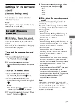
5

Press 

V

/

v

 repeatedly to select 

the parameter you want to 
adjust.

6

Press  

or 

b

 to enter the 

parameter.

7

Press 

V

/

v

 repeatedly to select 

the setting you want.

8

Press 

 to enter the setting.

To return to the previous 
display

Press 

B

 or RETURN/EXIT 

O

.

To exit the menu

Press MENU.

Note

Some parameters and settings may appear dimmed 
on the display. This means that they are either 
unavailable or fixed and unchangeable.

Summary of Contents for STR-DN1000

Page 1: ... 2009 Sony Corporation 4 136 735 11 1 Multi Channel AV Receiver Operating Instructions STR DN1000 ...

Page 2: ...serial numbers are located on the rear of the unit Record these numbers in the space provided below Refer to them whenever you call upon your Sony dealer regarding this product Model No _____________________________________ ________________ Serial No ______________________________________ ________________ This symbol is intended to alert the user to the presence of uninsulated dangerous voltage wi...

Page 3: ...used in accordance with the instructions may cause harmful interference to radio communications However there is no guarantee that interference will not occur in a particular installation If this equipment does cause harmful interference to radio or television reception which can be determined by turning the equipment off and on the user is encouraged to try to correct the interference by one or m...

Page 4: ...nology HDMI the HDMI logo and High Definition Multimedia Interface are trademarks or registered trademarks of HDMI Licensing LLC SIRIUS XM and all related marks and logos are trademarks of Sirius XM Radio Inc and its subsidiaries All rights reserved The font type Shin Go R installed in this receiver is provided by MORISAWA COMPANY LTD These names are the trademarks of MORISAWA COMPANY LTD and the ...

Page 5: ... Living Network Alliance The receiver is compatible with the S AIR function which allows transmission of sound between S AIR products wirelessly The following S AIR products can be used with the receiver Surround amplifier You can enjoy surround speaker sound wirelessly S AIR receiver You can enjoy receiver sound in another room These S AIR products can be purchased as an option the S AIR product ...

Page 6: ...nel of the SIRIUS Satellite Radio 58 Presetting SIRIUS Satellite Radio channels 59 Restricting access to specific channels Parental Lock 60 Enjoying Surround Sound Playing back with 2 channel sound 63 Playing back with multi channel surround 64 Enjoying a surround effect for music movie 67 Resetting sound fields to the initial settings 70 Amplifier Operations Using the setting menu 70 Settings for...

Page 7: ...alog audio INPUT MODE 108 Enjoying the sound images from other inputs 109 Using the Sleep Timer 111 Changing the brightness of the front panel display DIMMER 111 Enjoying the surround effect at low volume levels NIGHT MODE 112 Recording using the receiver 112 Using a bi amplifier connection 113 Using the Remote Operating each component using the remote 115 Programming the remote 117 Clearing all t...

Page 8: ...when the receiver is off or the DIMMER is set to 70 DOWN D MULTI CHANNEL DECODING lamp Lights up when multi channel audio signals are decoded page 128 E Display The current status of the selected componentor a list of selectable items appears here page 10 Name Function F MUTING Press to turn off the sound temporarily Press MUTING again to restore the sound page 48 126 G INPUT SELECTOR Press repeat...

Page 9: ...lay page 88 132 L DIMMER Press repeatedly to adjust the brightness of the display page 111 M INPUT MODE Press to select the input mode when the same components are connected to both digital and analog jacks page 108 N 2CH A DIRECT Press to select a sound field page 63 64 67 A F D MOVIE MUSIC O SPEAKERS Press to select the front speaker system page 38 P PHONES jack Connects to headphones page 127 ...

Page 10: ...The DIGITAL MEDIA PORT adapter is connected and DMPORT is selected No digital signal is being input When INPUT MODE is set to ANALOG or when the Analog Direct is being selected it also lights up Name Function D Dolby Digital Surround indicators D D EX D TrueHD Lights up one of the respective indicators when the receiver is decoding the corresponding Dolby Digital format signals Dolby Digital Dolby...

Page 11: ... surround channel signals Dolby Pro Logic Dolby Pro Logic II Dolby Pro Logic IIx Note These indicators do not light up when either the center speaker and surround speaker is not connected N BI AMP Lights up when SB Assign is set to BI AMP page 113 O EQ Lights up when the equalizer is activated Name Function P DTS HD indicators DTS HD MSTR DTS HD HI RES Lights up one of the respective indicators wh...

Page 12: ... ASSIGNABLE INPUT ONLY SURROUND BACK FRONT B BI AMP TV SIRIUS L R SURROUND for AUDIO EZW T100 A S AIR EZW T100 CAUTION Please do not remove the slot cover until you want to install the wireless transmitter Connects to a wireless transmitter not supplied page 99 B DMPORT DMPORT jack Connects to a Sony DIGITAL MEDIA PORT adapter page 23 With slot cover slot C ANTENNA section FM ANTENNA jack Connects...

Page 13: ...e image is output to a TV or a projector while the sound can be output from a TV or and speakers connected to this receiver page 21 26 E SPEAKERS section Connects to speakers page 19 F AUDIO INPUT OUTPUT section AUDIO IN OUT jacks Connects to a Super Audio CD player etc page 21 23 26 AUDIO OUT jack Connects to subwoofer page 19 G VIDEO AUDIO INPUT OUTPUT section AUDIO IN OUT jacks Connects to a VC...

Page 14: ...V on or off press TV D and then press AV 1 If you press 1 B at the same time it will turn off the receiver and other components SYSTEM STANDBY Note The function of the AV 1 switch changes automatically each time you press the input buttons E B 1 on standby Press to turn the receiver on or set it to the standby mode To turn off all components press 1 and AV 1 A at the same time SYSTEM STANDBY Savin...

Page 15: ...T Press to select a sound field page 63 64 67 A F D MOVIE MUSIC Name Function G SLEEP Press to activate the Sleep Timer function and the duration which the receiver turns off automatically page 111 H NIGHT MODE Press to activate the NIGHT MODE function page 112 I GUI MODE Press to display the GUI menu on the TV screen J V v B ba Press V v B b to select the menu items Then press to enter the select...

Page 16: ...al TV input or video input WIDEa Press TV D and then press WIDE repeatedly to select the wide picture mode Q MUTINGa Press to turn off the sound temporarily Press the button again to restore the sound To mute the sound of the TV press TV D and then press MUTING R TV VOL a Press TV D and then press TV VOL to adjust the TV volume level MASTER VOL a Press to adjust the volume level of all speakers at...

Page 17: ...Center speaker DSurround speaker left ESurround speaker right HSubwoofer You can enjoy high fidelity reproduction of DVD or Blu ray disc software recorded sound in the Surround EX format if you connect one additional surround back speaker 6 1 channel system or two surround back speakers 7 1 channel system Example of a 7 1 channel speaker system configuration AFront speaker left BFront speaker righ...

Page 18: ...aker system the angle A should be the same When you connect a 6 1 channel speaker system place the surround back speaker behind the listening position Since the subwoofer does not emit highly directional signals you can place it wherever you want ...

Page 19: ...er right a b c HSubwooferd VIDEO OUT MONITOR DIGITAL ASSIGNABLE C5V 7A MAX HDMI ANTENNA MPORT IN 4 IN 2 IN 3 AM VIDEO 1 AUDIO OUT VIDEO OUT OPTICAL IN AUDIO IN VIDEO IN AUDIO IN VIDEO IN BD L R SAT IN BD IN DVD IN OPTICAL COAXIAL TV SIRIUS AUDIO OUT SUBWOOFER L R L R FRONT A SURROUND BACK FRONT B BI AMP R 13 32 in 10 mm CENTER L SURROUND SPEAKERS ASSIGNABLE INPUT ONLY IN 1 OUT for AUDIO H A B B F ...

Page 20: ... 38 c If you are not using surround back speakers you can connect the front speakers to the SPEAKERS SURROUND BACK FRONT B BI AMP terminals using a bi amplifier connection page 113 Set SB Assign to BI AMP in the Speaker Settings menu page 73 d When you connect a subwoofer with an auto standby function turn off the function when watching movies If the auto standby function is set to on it turns to ...

Page 21: ...T AM OUT IN SA CD CD CD R VIDEO 1 TV AUDIO IN VIDEO IN SAT AUDIO OUT AUDIO OUT VIDEO OUT OPTICAL IN AUDIO IN VIDEO IN SUBWOOFER AUDIO IN VIDEO IN BD L R L R SPEAKERS SAT IN BD IN DVD IN OPTICAL CENTER FRONT A COAXIAL SURROUND BACK FRONT B BI AMP TV SIRIUS L R SURROUND VIDEO OUT MONITOR IN for AUDIO EZW T100 Y PB CB PR CR IN 2 IN 1 MONITOR OUT ASSIGNABLE INPUT ONLY HDMI IN 4 ASSIGNABLE INPUT ONLY I...

Page 22: ...he TV and the antenna aerial the image on the TV screen may be distorted In this case place the antenna aerial farther away from the receiver When connecting optical digital cords insert the plugs straight in until they click into place Do not bend or tie optical digital cords Tips The receiver has a video conversion function For details see Function for conversion of video signals page 33 The sou...

Page 23: ...components L R VIDEO OUT MONITOR DIGITAL ASSIGNABLE HDMI ANTENNA IN 4 ASSIGNABLE INPUT ONLY IN 3 IN 2 IN 3 IN 1 OUT AM Y PB CB COMPONENT VIDEO PR CR IN 2 IN 1 MONITOR OUT VIDEO 1 IN TV AUDIO IN VIDEO IN SAT AUDIO OUT AUDIO OUT VIDEO OUT OPTICAL IN AUDIO IN VIDEO IN SUBWOOFER AUDIO IN VIDEO IN BD L R L R SPEAKERS SAT IN BD IN DVD IN OPTICAL CENTER FRONT A COAXIAL ASSIGNABLE INPUT ONLY SURROUND BACK...

Page 24: ... the connector straight in As the connector of the DIGITAL MEDIA PORT adapter is fragile be sure to handle with care when placing or moving the receiver When connecting the DIGITAL MEDIA PORT adapter be sure the connector is inserted with the arrow mark facing towards the arrow mark on the DMPORT jack To detach the DIGITAL MEDIA PORT adapter press and hold A and then pull out the connector A ...

Page 25: ... the connecting jack See the illustration that follows Select the connection according to the jacks on your components Note Be sure to turn on the receiver when the video and audio of a playback component are being output to a TV via the receiver If the power supply of the receiver is not turned on neither video nor audio is transmitted Converting video signals This receiver is equipped with a fun...

Page 26: ...o rename the HDMI input so that it can be displayed on the receiver s display For details see Naming the input Name Input page 49 HDMI features A digital audio signals transmitted by HDMI can be output from the speakers connected to the receiver This signal supports Dolby Digital DTS and Linear PCM The receiver can receive Multi Linear PCM up to 8 channels with a sampling frequency of 192 kHz or l...

Page 27: ...N VIDEO IN BD L R L R SPEAKERS SAT IN BD IN DVD IN OPTICAL CENTER FRONT A COAXIAL ASSIGNABLE INPUT ONLY SURROUND BACK FRONT B BI AMP TV SIRIUS L R SURROUND IN EZW T100 TV OPTICAL IN SA CD CD CD R for AUDIO A AHDMI cable not supplied Sony recommends that you use an HDMI authorized cable or Sony HDMI cable BAudio cord not supplied a COptical digital cord not supplied a DVD player Audio video signals...

Page 28: ...e sure to turn on the receiver when the video and audio of a playback component are being output to a TV via the receiver If the power supply of the receiver is not turned on neither video nor audio is transmitted Audio signals sampling frequency bit length etc transmitted from an HDMI jack may be suppressed by the connected component Check the setup of the connected component if the image is poor...

Page 29: ...al digital cords Tip All the digital audio jacks are compatible with 32 kHz 44 1 kHz 48 kHz and 96 kHz sampling frequencies When you connect a component equipped with an OPTICAL jack set Input Assign in the Input Option menu Connecting a DVD player L R VIDEO OUT MONITOR L R DC5V 0 7A MAX HDMI ANTENNA DMPORT IN 4 ASSIGNABLE INPUT ONLY IN 2 IN 3 IN 1 OUT AM OUT IN SA CD CD CD R VIDEO 1 IN TV AUDIO I...

Page 30: ...s Tip All the digital audio jacks are compatible with 32 kHz 44 1 kHz 48 kHz and 96 kHz sampling frequencies When you connect a component equipped with an COAXIAL jack set Input Assign in the Input Option menu Connecting a Blu ray disc player L R VIDEO OUT MONITOR L R DC5V 0 7A MAX ANTENNA DMPORT IN 4 IN 2 IN 3 IN 1 OUT AM OUT IN SA CD CD CD R VIDEO 1 IN TV AUDIO IN VIDEO IN SAT AUDIO OUT AUDIO OU...

Page 31: ...s are compatible with 32 kHz 44 1 kHz 48 kHz and 96 kHz sampling frequencies Connecting a satellite tuner set top box L R VIDEO OUT MONITOR L R DC5V 0 7A MAX HDMI ANTENNA DMPORT IN 4 ASSIGNABLE INPUT ONLY IN 2 IN 3 IN 1 OUT AM OUT IN OUT SA CD CD CD R VIDEO 1 IN TV AUDIO OUT AUDIO OUT VIDEO OUT OPTICAL IN AUDIO IN VIDEO IN SUBWOOFER AUDIO IN VIDEO IN BD L R L R SPEAKERS CENTER FRONT A SURROUND BAC...

Page 32: ...Connecting components with analog video and audio jack L R VIDEO OUT MONITOR L R DIGITAL ASSIGNABLE DC5V 0 7A MAX HDMI ANTENNA DMPORT IN 4 ASSIGNABLE INPUT ONLY IN 3 IN 2 IN 3 IN 1 OUT AM Y PB CB COMPONENT VIDEO OUT IN PR CR IN 2 IN 1 MONITOR OUT SA CD CD CD R IN TV AUDIO IN VIDEO IN SAT AUDIO OUT OPTICAL IN AUDIO IN VIDEO IN BD L R SPEAKERS SAT IN BD IN DVD IN OPTICAL CENTER FRONT A COAXIAL ASSIG...

Page 33: ...ideo Video Settings menu page 79 a Video signals are up converted and output through the video converter f The same type of signal as that of the input signal is output Video signals are not converted X Video signals are not output L R L R DIGITAL ASSIGNABLE DC5V 0 7A MAX ANTENNA DMPORT AM OUT IN SA CD CD CD R IN TV AUDIO OUT OPTICAL IN SUBWOOFER L R SPEAKERS SAT IN BD IN DVD IN OPTICAL CENTER FRO...

Page 34: ...tion of video signals protected by copyright technology is converted Resolution of up to 480p can be output to the COMPONENT VIDEO MONITOR OUT jacks The HDMI OUT jack has no restriction on resolution Video signals for which the resolution has been converted cannot be output from either the COMPONENT VIDEO MONITOR OUT jacks or the HDMI OUT jack The video signals are output from the HDMI OUT jack wh...

Page 35: ...a aerial After connecting the FM wire antenna aerial keep it as horizontal as possible L R VIDEO OUT MONITOR L R DIGITAL ASSIGNABLE DC5V 0 7A MAX HDMI ANTENNA DMPORT IN 4 ASSIGNABLE INPUT ONLY IN 3 IN 2 IN 3 IN 1 OUT AM Y PB CB COMPONENT VIDEO OUT IN PR CR IN 2 IN 1 MONITOR OUT SA CD CD CD R VIDEO 1 IN TV AUDIO IN VIDEO IN SAT AUDIO OUT AUDIO OUT VIDEO OUT OPTICAL IN AUDIO IN VIDEO IN SUBWOOFER AU...

Page 36: ...orming the following procedure This procedure can also be used to return settings you have made to their factory defaults Be sure to use the buttons on the receiver for this operation 1 Press 1 to turn off the receiver 2 Hold down 1 for 5 seconds After CLEARING appears on the display for a while CLEARED appears All the settings you have changed or adjusted are reset to the initial settings Connect...

Page 37: ...teries with new ones 7 Displaying the GUI menu on the TV screen You can select the functions or change the settings of the receiver by using the GUI menu on the TV screen Follow the procedure below to make the settings so that the GUI menu appears on the TV screen Note GUI menu does not appear on the TV screen when you have connected your TV to the MONITOR VIDEO OUT jack Tip See Operating without ...

Page 38: ...PEAKERS repeatedly until the SP A SP B or SP A B indicators on the display does not light up ALL OFF appears on the display for a while Note You cannot switch the front speaker system by pressing SPEAKERS when the headphones are connected Input Music Video VIDEO 1 VIDEO 2 BD DVD SAT To select Light up The front speakers connected to the SPEAKERS FRONT A terminals SP A The front speakers connected ...

Page 39: ...n press 6 Press V v repeatedly to select SB Assign then press or b 7 Press V v repeatedly to select Speaker B then press The same signals output from the SPEAKERS FRONT A terminals can be output from the SPEAKERS SURROUND BACK FRONT B BI AMP terminals To exit the menu Press MENU Notes Set SB Assign to Speaker B before you perform Auto Calibration If you set SB Assign to Speaker B the speaker level...

Page 40: ... microphone During the measurement the sound that comes out of the speakers is very loud The volume of the sound cannot be adjusted Pay attention to the presence of children or to the effect on your neighborhood Perform the measurement in a quiet environment to avoid the effect of noise and get a more accurate measurement If there are any obstacles in the path between the optimizer microphone and ...

Page 41: ... After MENU ON appears on the display for a while GUI appears and the GUI menu appears on the TV screen Press MENU if the GUI menu does not appear on the TV screen 2 Press V v repeatedly to select Settings then press or b The Settings menu list appears on the TV screen 1 MASTER VOLUME SPEAKERS PHONES 2 CH A DIRECT A F D MOVIE MUSIC INPUT MODE DIMMER DISPLAY VIDEO 2 IN VIDEO L AUDIO R AUTO CAL MIC ...

Page 42: ...put buttons on the remote or press the INPUT SELECTOR repeatedly on the receiver Press MUTING Press SPEAKERS on the receiver Change the volume level Connect the headphones 1 Confirm the measurement result When the measurement ends a beep sounds 2 Press V v repeatedly to select the item you want then press Count Down Please press enter key to stop 5 Auto Calibration RETURN CANCEL Auto Calibration T...

Page 43: ...r microphone and speakers and the shape of the room It is recommended that you follow the measurement results However you can change those settings in the Speaker Settings menu Save the measurement results first then try to change the settings if you want Distance Displays the measurement result for speaker distance Level Displays the measurement result for speaker level Exit Exits the setting pro...

Page 44: ...front speakers are connected or only one front speaker is connected The optimizer microphone is not connected Either the left or right surround speakers is not connected Surround back speakers are connected even though surround speakers are not connected Connect the surround speaker s to the SPEAKERS SURROUND terminals The surround back speaker is connected only to the SPEAKERS SURROUND BACK FRONT...

Page 45: ... V v repeatedly to select a menu you want 3 Press or b to enter the menu The menu item list appears on the TV screen 4 Press V v repeatedly to select the menu item you want to adjust 5 Press or b to enter the menu item 6 Press V v repeatedly to select the parameter you want to adjust 7 Press or b to enter the parameter Using the menu 2CH A DIRECT A F D MOVIE MUSIC RESOLUTION MENU RETURN EXIT TOOLS...

Page 46: ...ess MENU if the GUI menu does not appear on the TV screen 2 Press V v repeatedly to select a menu you want 3 Press or b to enter the menu The menu item list appears on the TV screen Example when you select Input Menu icon Description Input Selects the input source component connected to the receiver page 47 Music Selects the music from the audio component connected to the DIGITAL MEDIA PORT adapte...

Page 47: ...ss MENU if the GUI menu does not appear on the TV screen Input VIDEO 1 VIDEO 2 DVD SAT BD Name lnput Input Assign Playback 1 2 3 4 5 6 7 8 9 0 10 ENT MEM 2CH A DIRECT A F D MOVIE MUSIC THEATER SYSTEM STANDBY RM SET UP 1 CLEAR 10 SHIFT TUNING TUNING DISC SKIP D TUNING RESOLUTION m M X x MUTING VIDEO 1 VIDEO 2 BD SAT TV HDMI 3 HDMI 2 HDMI 1 HDMI 4 SA CD CD DMPORT TUNER TV VOL MASTER VOL TV CH PRESET...

Page 48: ...utton on the remote To turn the volume up or down quickly press and hold the button To make a fine adjustment press the button and release it immediately To activate the muting function Press MUTING The muting function will be canceled when you do the following Press MUTING again Increase the volume Turn off the receiver To avoid damaging your speakers Before you turn off the receiver be sure to t...

Page 49: ... MEDIA PORT adapter see Connecting audio components page 23 Sony offers the following DIGITAL MEDIA PORT adapters as of May 2009 TDM BT1 BT10 Bluetooth Wireless Audio Adapter TDM NW10 DIGITAL MEDIA PORT Adapter TDM NC1 Wireless Network Audio Client TDM iP10 iP50 DIGITAL MEDIA PORT Adapter TDM MP10 DIGITAL MEDIA PORT Adapter The DIGITAL MEDIA PORT adapter is an optional product Notes Do not connect...

Page 50: ...You can select a track you want and play it back on each GUI screen iPod This mode is for the TDM iP50 If the option menu does not appear on the screen refer to the operating instructions of the connected component When an adapter other than iPod is connected a hierarchical menu does not appear To operate the TDM iP50 or TDM NC1 using the GUI menu of the receiver 1 Make sure that System GUI is sel...

Page 51: ...ists Playlist Track Artists Artist Album Track Albums Album Track Songs Track Genres Genre Artist Album Track Composers Composer Track Audiobooks Audiobook Network Client Music Surfina Albumc Track Playlista Playlist Track Web Radioa Station Program Music Libraryb Album Track iPod Movies Content TV Shows Episode Content Music Videos Artist Content Video Playlists Video Playlist Content Video Podca...

Page 52: ... Message appears Explanation No Adapter The adapter is not connected No Device There is no device connected to the adapter No Audio No audio file was found Loading The data is being read No Server There is no server connected No Track No track was found No Item No item was found Connecting Connecting to the server Configuring The network is setting up Warning Check the display of the DIGITAL MEDIA...

Page 53: ...en press You can enter the frequency of a station directly by using the numeric buttons 1 Press GUI MODE After MENU ON appears on the display for a while GUI appears and the GUI menu appears on the TV screen Press MENU if the GUI menu does not appear on the TV screen 2 Press V v repeatedly to select FM or AM then press or b 3 Press V v repeatedly to select Direct Tuning then press or b 4 Press SHI...

Page 54: ...ress MENU if the GUI menu does not appear on the TV screen 2 Press V v repeatedly to select FM or AM then press or b 3 Tune in the station that you want to preset using Automatic Tuning page 53 or Direct Tuning page 53 In case of poor FM stereo reception switch the FM reception mode page 53 4 Press TOOLS OPTIONS The option menu appears 5 Press V v repeatedly to select Memory then press or b 6 Pres...

Page 55: ... from categories ranging from Pop Rock Country R B Dance Jazz Classical and many more plus coverage of all the top professional and college sports including play by play games from select leagues and teams Additional programming includes expert sports talk uncensored entertainment comedy family programming local traffic and weather and news from your most trusted sources Once you ve purchased a SI...

Page 56: ...atellite Radio System Service not available in Alaska or Hawaii Connecting the SIRIUS Satellite Radio Connect the SiriusConnect Home tuner When you use the SiriusConnect Home tuner with this receiver be sure to connect the AC power adaptor supplied with the tuner to a wall outlet Note Keep the SiriusConnect Home tuner antenna and AC power adaptor away from the speaker cords and the power cord to a...

Page 57: ...D using the display on the receiver 1 Press GUI MODE After MENU ON appears on the display for a while GUI appears and the GUI menu appears on the TV screen Press MENU if the GUI menu does not appear on the TV screen 2 Press V v repeatedly to select SR then press or b 3 Press TOOLS OPTIONS then press V v repeatedly to select Antenna then press or b 4 While checking the quality of the reception adju...

Page 58: ...ess TOOLS OPTIONS then press V v repeatedly to select Category Mode 4 Press V v repeatedly to select the channel then press The selected channel is being received The channel information is displayed on the TV screen Note When you select a channel in the Category Mode the channel you selected may not be the one in the category you want This is because one channel may belong to more than one catego...

Page 59: ...t numbers You can preset up to 30 SIRIUS Satellite Radio channels 1 Press GUI MODE After MENU ON appears on the display for a while GUI appears and the GUI menu appears on the TV screen Press MENU if the GUI menu does not appear on the TV screen 2 Press V v repeatedly to select SR then press or b 3 Select a channel you want to preset using Category Tuning page 58 or Direct Tuning page 59 4 Press T...

Page 60: ...ress TOOLS OPTIONS then press V v repeatedly to select Preset Mode Restricting access to specific channels Parental Lock You can restrict access to certain channels using your own lock code The lock code is set to 0000 as the default Change the lock code before you use this function for the first time See To change the lock code Lock Code page 61 1 Select a channel you want to lock using Category ...

Page 61: ...s been changed appears To listen to the locked channels 1 Select a locked channel you want to listen to using Direct Tuning page 59 Enter your 4 digit lock code appears 2 Press SHIFT then press the numeric buttons to enter your 4 digit lock code The channel is tuned in To cancel the Parental Lock 1 Select a channel you want to unlock using Direct Tuning page 59 2 Press TOOLS OPTIONS The option men...

Page 62: ...me tuner is not connected properly Check all the connections and then turn the system on again Also make sure if the AC adaptor supplied with the SiriusConnect Home tuner is connected to a wall socket Invalid INVALID You have entered an invalid channel number The channel to be tuned in is void due to the change by the broadcast service or the receiving condition is not good Locked CH LOCKED CH The...

Page 63: ...joying Surround Sound 2CH A DIRECT A F D MOVIE MUSIC RESOLUTION HDMI 4 INPUT MODE SLEEP NIGHT MODE 2CH A DIRECT Types of 2CH mode 2CH mode appears on TV screen Effect 2 CHANNEL STEREO 2ch stereo The receiver outputs the sound from the front left right speakers only There is no sound from the subwoofer Standard 2 channel stereo sources completely bypass the sound field processing and multi channel ...

Page 64: ...T MODE SLEEP NIGHT MODE CATEGORY V v B b GUI MODE MENU A F D A F D mode appears on TV screen Multi channel audio after decoding Effect A F D AUTO A F D Auto Detecting automatically Presets the sound as it was recorded encoded without adding any surround effects ENHANCED SURROUND MODE Enhanced Sur You can select the surround sound effect you want For details see Setting a multi channel surround sou...

Page 65: ... which is a low pass sound effect output to a subwoofer from a 2 channel signal However the low frequency signal is not generated for Neo 6 Cinema or Neo 6 Music when all speakers are set to Large In order to take full advantage of the Dolby Digital bass redirection circuitry we recommend setting the subwoofer s cut off frequency as high as possible 1 Start playing a sound source you want to liste...

Page 66: ...Performs Dolby Pro Logic IIx mode decoding A source recorded in 2 channel or 5 1 channel format is decoded into 7 1 channels This setting is ideal for movies encoded in Dolby Surround In addition this mode can reproduce sound in 7 1 channel system for watching videos of overdubbed or old movies NEO 6 CINEMA Neo 6 Cinema 7 channel signals Performs DTS Neo 6 Cinema mode decoding A source recorded in...

Page 67: ... of the Sony Pictures Entertainment scoring stage This mode is ideal for watching musicals or films where orchestra music is featured in the soundtrack VIRTUAL MULTI DIMENSION DCS V M Dimension Creates many virtual speakers from a single pair of actual surround speakers Music HALL Hall Reproduces the acoustics of a classical concert hall JAZZ CLUB Jazz Club Reproduces the acoustics of a jazz club ...

Page 68: ...sound is output from the subwoofer if all the speakers are set to Large on the Speaker Settings menu However the sound will be output from the subwoofer if the digital input signal contains LFE signals the front and surround speakers are set to Small the sound field for movie is selected Portable Audio is selected The effects provided by the virtual speakers may cause increased noise in the playba...

Page 69: ... instructions of the playback component b Signals with a sampling frequency of more than 96 kHz are played back at 96 kHz Digital audio formats supported by the receiver Audio format Maximumnumber of channels Connection of the playback component and the receiver COAXIAL OPTICAL HDMI Dolby Digital 5 1ch a a Dolby Digital EX 6 1ch a a Dolby Digital Plusa 7 1ch a Dolby TrueHDa 7 1ch a DTS 5 1ch a a D...

Page 70: ...ODE by following the steps in 7 Displaying the GUI menu on the TV screen page 37 1 Press GUI MODE After MENU ON appears on the display for a while GUI appears and the GUI menu appears on the TV screen Press MENU if the GUI menu does not appear on the TV screen 1 MASTER VOLUME SPEAKERS PHONES 2 CH A DIRECT A F D MOVIE MUSIC INPUT MODE DIMMER DISPLAY VIDEO 2 IN VIDEO L AUDIO R AUTO CAL MIC MULTI CHA...

Page 71: ... AM AM SR SR Setting Auto Cal Speaker Surround EQ Audio Setting Speaker Surround EQ Audio Auto Cal Menu Description Auto Cal Sets the speaker level or distance and makes the measurement automatically page 72 Speaker Sets the speaker position and impedance manually page 73 Surround Adjusts the sound field surround effect you choose page 77 EQ Adjusts the equalizer bass treble sound page 78 Audio Se...

Page 72: ...r the listening environment You can select the seating position you want and register the measurement results of the Auto Calibration for that seating position 1 Press V v repeatedly to select Position then press or b 2 Press V v repeatedly to select the position Position 1 2 3 for which you want to register the measurement result then press 3 Press V v repeatedly to select Auto Cal Start then pre...

Page 73: ... BI AMP terminals select Speaker B page 38 BI AMP If you connect front speakers in a bi amplifier configuration select BI AMP page 113 OFF If you have not connected surround back speakers select OFF Note Set SB Assign to OFF then connect the surround back speakers to this receiver when you want to change the connection from a bi amplifier connection or front speakers B connection to a surround bac...

Page 74: ...ker then press Large If you connect large speakers that will effectively reproduce bass frequencies select Large Normally select Large Small If the sound is distorted or you feel a lack of surround effects when using multi channel surround sound select Small to activate the bass redirection circuitry and output the bass frequencies of each channel from the subwoofer or other Large speakers Tips Th...

Page 75: ...tedly to adjust the speaker level then press To output test tone from adjacent speakers You can output test tone from adjacent speakers so that you can adjust the balance between the speakers 1 Press B b repeatedly to select Phase Noise then press The Phase Noise screen appears 2 Press V v repeatedly to adjust the parameter then press OFF FL SR SL FL SB SL SBL SL SR SB SBR SBL SR SBR SR SL FR SR F...

Page 76: ...ital sources only MAX The dynamic range is compressed dramatically STD The dynamic range is compressed as intended by the recording engineer AUTO The dynamic range is applied automatically with Dolby TrueHD source or other source is set to OFF OFF The dynamic range is not compressed Tips Dynamic range compressor lets you compress the dynamic range of the soundtrack based on the dynamic range infor...

Page 77: ...d mode You can select the decoding mode for the sound field For details on the decoding modes available see Setting a multi channel surround sound effect page 65 Pro Logic II Performs Dolby Pro Logic II decoding A source recorded in 2 channel format is decoded into 5 1 channels Pro Logic IIx Performs Dolby Pro Logic IIx decoding A source recorded in 2 channel or 5 1 channel format is decoded into ...

Page 78: ...s menu You can make settings for the audio to suit your preference x A V Sync Synchronizes audio with video output Lets you delay the output of audio to minimize the time gap between audio output and visual display You can adjust the delay from 0 ms to 300 ms in 10 ms steps Notes This parameter is useful when you use a large LCD or plasma monitor or a projector This parameter is not valid when Ana...

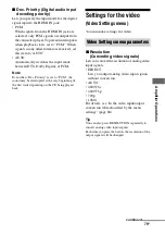
Page 79: ...t to PCM the sound may be interrupted at the very beginning of the first track depending on the CD being played back Settings for the video Video Settings menu You can make settings for video x Resolution Converting video signals Lets you convert the resolution of analog video input signals DIRECT Lets you output analog video input signals without conversion AUTO 480 576i 480 576p 720p 1080i For d...

Page 80: ...s not support in the Resolution menu the images from the TV cannot be output correctly Converted HDMI image output signals do not support x v Color Converted HDMI image output signals do not support Deep Color When HDMI OUT jack is connected there is no up converted video signal output from COMPONENT VIDEO MONITOR OUT jacks The COMPONENT VIDEO MONITOR OUT jacks have the component signal direct out...

Page 81: ... AMP TV AMP The sound is output from TV s speaker and the speakers connected to the receiver Notes The sound quality of the playback component depends on the TV s sound quality such as the number of channels and the sampling frequency etc When the TV has stereo speakers the sound output from the receiver is also stereo as that of the TV even if you play back multi channel source When you connect t...

Page 82: ...ng the channel for better sound transmission page 105 x S AIR Stby S AIR standby You can enjoy the S AIR receiver while the S AIR main unit is in standby mode For details see Enjoying the S AIR receiver while the S AIR main unit is in standby mode page 107 Operating without connecting to a TV You can operate this receiver using the display even if you do not use a GUI when a TV is not connected Pr...

Page 83: ...e parameter 7 Press V v repeatedly to select the setting you want 8 Press to enter the setting To return to the previous display Press B or RETURN EXIT O To exit the menu Press MENU Note Some parameters and settings may appear dimmed on the display This means that they are either unavailable or fixed and unchangeable ...

Page 84: ...SL FL FR CNT FR FL CNT OFF Front left speaker levelb FL LEVEL FL 10 0 dB to FL 10 0 dB 0 5 dB per step FL 0 0 dB Front right speaker levelb FR LEVEL FR 10 0 dB to FR 10 0 dB 0 5 dB per step FR 0 0 dB Center speaker levelb CNT LEVEL CNT 20 0 dB to CNT 10 0 dB 0 5 dB per step CNT 0 0 dB Surround left speaker levelb SL LEVEL SL 20 0 dB to SL 10 0 dB 0 5 dB per step SL 0 0 dB Surround right speaker le...

Page 85: ... 32 9 SL 1 00 m to SL 10 00 m 1 inch 0 01 m step SL 9 10 3 00 m Surround right speaker distanceb SR DIST SR 3 3 to SR 32 9 SR 1 00 m to SR 10 00 m 1 inch 0 01 m step SR 9 10 3 00 m Surround back speaker distanceb SB DIST SB 3 3 to SB 32 9 SB 1 00 m to SB 10 00 m 1 inch 0 01 m step SB 9 10 3 00 m Surround back left speaker distanceb SBL DIST SBL 3 3 to SBL 32 9 SBL 1 00 m to SBL 10 00 m 1 inch 0 01...

Page 86: ...REO Naming preset stations NAME IN For details see Naming preset stations Name Input page 55 Parental lockf PARENTAL OFF ON OFF Lock code editf CODE EDIT For details see Restricting access to specific channels Parental Lock page 60 SIRIUS antenna aiming modef SR ANT AIM For details see Checking receiving conditions Antenna Aiming page 57 SIRIUS radio IDf SIRIUS ID For details see Checking the SIRI...

Page 87: ...r Menu Display Parameters Display Settings Initial setting Video settings VIDEO Resolution RESOLUTION DIRECT AUTO 480 576i 480 576p 720p 1080i AUTO Video input assignment V ASSIGN VIDEO 1 c COMPONENT1 COMPONENT2 COMPONENT3 COMPOSITE HDMI1 HDMI2 HDMI3 HDMI4 NONE VIDEO 2 c BD c DVD c SAT c SA CD CD c Switching component signals COMP DEC DEC ON DEC OFF DEC OFF HDMI settings HDMI Control for HDMI CTRL...

Page 88: ...e display while GUI is shown on the display Press GUI MODE repeatedly to select MENU OFF For details on the Auto Calibration see 9 Calibrating the appropriate speaker settings automatically Auto Calibration page 40 See Before you perform Auto Calibration page 40 before performing the Auto Calibration To operate on the receiver 1 Press GUI MODE repeatedly to select MENU OFF 2 Press AMP Receiver ope...

Page 89: ...ults first then try to change the settings if you want Measurement result Display Explanation When the measurement process completes properly COMPLETE Proceed to step 2 When the measurement process fails E xxx xx See Message list after Auto Calibration measurement page 44 Item Explanation RETRY Performs the Auto Calibration again SAVE EXIT Saves the measurement results and exits the setting proces...

Page 90: ...und field type appears on the display To select Enhanced Surround Mode 1 Press AMP 2 Press MENU 3 Press V v repeatedly to select SURROUND then press or b 4 Press V v repeatedly to select E SUR MODE then press or b 5 Press V v repeatedly to select the Enhanced Surround Mode you want then press Note The selected Enhanced Surround Mode can only be applied if you have selected E SURROUND by pressing A...

Page 91: ... 2 Press SHIFT then press ENT MEM MEM lights up for a few seconds Perform steps 3 and 4 before MEM disappears 3 Press PRESET or PRESET to select a preset number 30 FM and 30 AM preset numbers are available If MEM disappears before you select the preset number start again from step 2 4 Press ENT MEM or b If SHIFT indicator is light off before you press ENT MEM press SHIFT The station is stored as t...

Page 92: ...annel 0 3 Check the SIRIUS ID on the display and write it in the space provided here SIRIUS ID _________________________ Selecting channels from a category CATEGORY TUNING 1 Press TUNER repeatedly to select SIRIUS You can also use INPUT SELECTOR on the receiver 2 Press CATEGORY MODE repeatedly to select ONE CAT ALL CAT You can select a channel from all the categories The initial setting is ALL CAT...

Page 93: ...unction By connecting Sony components that are compatible with the BRAVIA Sync with an HDMI cable not supplied operation is simplified as follows One Touch Play When you play back a component such as a DVD Blu ray disc player the receiver and the TV are turned on automatically and switched to the appropriate HDMI input In case the receiver or and the TV is in standby mode they will be turned on au...

Page 94: ...l for HDMI function of the receiver can be turned on simultaneously by turning the Control for HDMI function of the TV on 1 Make sure that the receiver TV and playback components are connected using an HDMI cable not supplied The respective components must be compatible with the Control for HDMI function 2 Turn on the receiver TV and playback components 3 Turn the Control for HDMI function of the ...

Page 95: ...hat the image from the connected component is displayed For details on setting the TV and connected components refer to the operating instructions of the respective components Notes When you unplug the HDMI cable or change the connection perform the steps given in When your TV is compatible with the Control for HDMI Easy Setting function page 94 or When your TV is not compatible with the Control f...

Page 96: ...nction is turned on the receiver will turn on and switch to the appropriate input automatically TV sound is output from the speakers connected to the receiver and the volume of the TV is minimized simultaneously You can also use the System Audio Control function as follows If you turn on the receiver while the TV is turned on the System Audio Control function will automatically be set to on and th...

Page 97: ...ducts When you purchase the S AIR product you need to establish sound transmission page 99 There are two types of S AIR product S AIR main unit this receiver The S AIR main unit is for transmitting sound You can use up to 3 S AIR main units The number of usable S AIR main unit depends on the use environment S AIR sub unit not supplied The S AIR sub unit is for receiving sound Surround amplifier Yo...

Page 98: ...ronic equipment influence The following may cause interference or cross talk Cellular phones cordless phones Wireless LAN personal computers Game machines using radio signals Microwave ovens Other factors The following may cause poor reception Materials or structures such as walls and floors The location where an S AIR product is placed When using S AIR products place them as far as possible from ...

Page 99: ... transmitter into the S AIR main unit 1 Remove the screws and detach the slot cover Notes Remove the screws from the slot cover bearing the caution mark Do not remove other screws The slot cover is no longer necessary However keep it after detaching 2 Insert the wireless transmitter Inserting the wireless transmitter transceiver VIDEO OUT MONITOR L R DIG DC5V 0 7A MAX ANTENNA DMPORT IN 3 AM Y PB C...

Page 100: ...on You can use multiple S AIR main unit by setting a different ID for each unit To set the ID of the S AIR main unit 1 Press GUI MODE After MENU ON appears on the display for a while GUI appears and the GUI menu appears on the TV screen Press MENU if the GUI menu does not appear on the TV screen 2 Press V v repeatedly to select Settings then press or b The Settings menu list appears on the TV scre...

Page 101: ...AIR receiver To use multiple S AIR main units You can use multiple S AIR main units by setting a different ID for each component Notes Sources with copyright protection may not be playable on S AIR sub unit When sound transmission is established sound can only be output from the S AIR receiver if you connect the components to this receiver via the analog jacks The sound cannot be output if the com...

Page 102: ...AIR main unit see To set the ID of the S AIR main unit page 100 To set the ID of the S AIR sub unit refer to the operating instructions supplied with the S AIR sub unit Pairing the S AIR main unit with a specific S AIR sub unit Pairing operation ID A ID A ID A 1 MASTER VOLUME SPEAKERS PHONES 2 CH A DIRECT A F D MOVIE MUSIC INPUT MODE DIMMER DISPLAY VIDEO 2 IN VIDEO L AUDIO R AUTO CAL MIC MULTI CHA...

Page 103: ...AIR sub unit Notes Perform pairing within 5 minutes in step 6 If you do not pairing is recognized as failed and the screen changes accordingly In this case see If pairing fails page 103 When sound transmission is established Pairing complete To perform pairing to another S AIR sub unit select Continue appears 9 Press B b repeatedly to select Finish or Continue then press Finish Finishes pairing Co...

Page 104: ...er For details see Pairing the S AIR main unit with a specific S AIR sub unit Pairing operation page 102 2 Press GUI MODE After MENU ON appears on the display for a while GUI appears and the GUI menu appears on the TV screen Press MENU if the GUI menu does not appear on the TV screen 3 Press V v repeatedly to select Settings then press or b The Settings menu list appears on the TV screen 4 Press V...

Page 105: ... Changing the channel for better sound transmission If you use multiple wireless systems which sharing the 2 4 GHz band such as wireless LAN or Bluetooth the transmission of S AIR products or other wireless systems may be unstable In this case transmission may be improved by changing the RF Change setting 1 Press GUI MODE After MENU ON appears on the display for a while GUI appears and the GUI men...

Page 106: ...unit can be performed using one of the following channels S AIR ID A equivalent channel for IEEE 802 11b g channel 1 S AIR ID B equivalent channel for IEEE 802 11b g channel 6 S AIR ID C equivalent channel for IEEE 802 11b g channel 11 The transmission may be improved by changing the transmission channel frequency of the other wireless system s For details refer to the operating instructions of th...

Page 107: ...UI menu appears on the TV screen Press MENU if the GUI menu does not appear on the TV screen 2 Press V v repeatedly to select Settings then press or b The Settings menu list appears on the TV screen 3 Press V v repeatedly to select S AIR then press The S AIR menu appears Note When the S AIR transmitter not supplied is not inserted into the S AIR main unit S AIR cannot be selected 4 Press V v repea...

Page 108: ...udio INPUT MODE When you connect components to both digital and analog audio input jacks on the receiver you can fix the audio input mode to either of them or switch from one to the other depending on the type of material you intend to watch 1 Press the input button You can also use the INPUT SELECTOR on the receiver 2 Press INPUT MODE repeatedly to select the audio input mode The selected audio i...

Page 109: ... Input Option menu 1 Press GUI MODE After MENU ON appears on the display for a while GUI appears and the GUI menu appears on the TV screen Press MENU if the GUI menu does not appear on the TV screen 2 Press V v repeatedly to select Input then press or b 3 Press V v repeatedly to select the input name you want to assign 4 Press TOOLS OPTIONS 5 Press V v repeatedly to select Input Assign then press ...

Page 110: ...ne HDMI input to the same input You cannot reassign more than one digital audio input to the same input You cannot reassign more than one component video input to the same input Input name VIDEO1 VIDEO2 BD DVD SAT SA CD CD CD R HDMI1 HDMI2 HDMI3 HDMI4 Assignable video input jacks COMP 1 a a a a a a COMP 2 a a a a a a COMP 3 a a a a a a CVBS a a a a HDMI1 a a a a a a a HDMI2 a a a a a a a HDMI3 a a...

Page 111: ...e remaining time appears on the display If you press SLEEP again the Sleep Timer will be canceled Changing the brightness of the front panel display DIMMER You can change the brightness of the front panel display 1 Press AMP 2 Press MENU 3 Press V v repeatedly to select SYSTEM then press or b 4 Press V v repeatedly to select DIMMER then press or b 5 Press V v repeatedly to select the setting you w...

Page 112: ... automatically set to MAX Recording using the receiver You can record from a video audio component using the receiver Refer to the operating instructions supplied with your recording component You can record onto a CD R using the receiver Refer to the operating instructions supplied with your CD recorder 1 Press one of the input buttons to select the playback component You can also use INPUT SELEC...

Page 113: ...i amplifier connection To connect speakers Connect the jacks on the Lo or Hi side of the front speakers to the SPEAKERS FRONT A terminals and connect the jacks on the Hi or Lo side of the front speakers to the SPEAKERS SURROUND BACK FRONT B BI AMP terminals Make sure that metal fittings of Hi Lo attached to the speakers have been removed from the speakers Not doing so may cause a malfunction of th...

Page 114: ...b 6 Press V v repeatedly to select SB Assign then press or b 7 Press V v repeatedly to select BI AMP then press or b The same signals output from the SPEAKERS FRONT A terminals can be output from the SPEAKERS SURROUND BACK FRONT B BI AMP terminals To exit the menu Press MENU Notes Set SB Assign to BI AMP before you perform Auto Calibration If you set SB Assign to BI AMP the speaker level and dista...

Page 115: ...ding to the components you are using you can control non Sony and other Sony components that the remote is initially unable to control page 117 1 Press the input button that matches the connected component that you want to operate 2 Press the appropriated buttons to use the function listed in the table below Note You may not be able to operate some functions for the components you are using Using ...

Page 116: ...AV 1 z z z z z z z z z z z Numeric buttons z z z z z z z z z z z z z TV INPUT WIDE z 10 CLEAR z z z z z z z z z z z ENT MEM z z z z z z z 1 z z z z z TOOLS OPTIONS z z z z z z z DISPLAY z z z z z z z z z z RETURN EXIT O z z z z z z z z z V v B b MENU HOME z z z z z z z z z z z z z z z z z z 2 z z z z z z z z z z m TUNING M TUNING z z z z z z z z z z z z DISC SKIP z z z 3 z N X x z z z z z z z z z ...

Page 117: ...hich you cannot program the remote such as DMPORT etc the RM SET UP indicator keeps flashing 3 Press numeric buttons to enter the numeric code or one of the codes if more than one code exists corresponding to the component and the maker of the component you want to control See the tables on page 118 121 for information on the numeric code s Note For a TV remote code value only numbers in the 500 s...

Page 118: ...s Notes The numeric codes are based on the latest information available for each brand There is a chance however that your component will not respond to some or all of the codes All of the input buttons on this remote may not be available when used with your particular component To control a tuner To control a CD player To control a DAT deck To control a tape deck The numeric codes corresponding t...

Page 119: ...IPS 407 PIONEER 409 410 RCA 414 SAMSUNG 416 422 TOSHIBA 404 421 ZENITH 418 420 Maker Code s SONY 401 402 403 Maker Code s SONY 411 Maker Code s SONY 401 402 403 Maker Code s SONY 501 502 AIWA 501 536 539 AKAI 503 AOC 503 CENTURION 566 CORONADO 517 CURTIS MATHES 503 551 566 567 DAYTRON 517 566 DAEWOO 504 505 506 507 515 544 FISHER 508 545 FUNAI 548 FUJITSU 528 GOLDSTAR LG 503 512 515 517 534 544 55...

Page 120: ...549 TOSHIBA 535 539 540 541 551 TELEFUNKEN 530 537 538 547 549 558 TEKNIKA 517 518 567 WARDS 503 517 566 YORK 566 ZENITH 542 543 567 GE 503 509 510 544 LOEWE 515 534 556 Maker Code s SONY 601 602 603 PIONEER 606 Maker Code s Maker Code s SONY 605 Maker Code s SONY 701 702 703 704 705 706 AIWA 710 750 757 758 AKAI 707 708 709 759 BLAUPUNKT 740 EMERSON 711 712 713 714 715 716 750 FISHER 717 718 719 ...

Page 121: ...NERAL ELECTRIC GE 866 GRUNDIG 859 860 HUMAX 846 847 THOMSON 857 861 864 876 PACE 848 849 850 852 862 863 864 PANASONIC 818 855 PHILIPS 856 857 858 859 860 864 874 NOKIA 851 853 854 864 RCA PROSCAN 866 871 BITA HITACHI 868 HUGHES 867 JVC Echostar Dish Network 873 MITSUBISHI 872 SAMSUNG 875 TOSHIBA 869 870 Maker Code s SONY 821 822 823 HAMLIN REGAL 836 837 838 839 840 JERROLD G I MOTOROLA 806 807 80...

Page 122: ...video signal information The luminance signal Y and chrominance signal C are combined and transmitted together x Crossover frequency The frequency at which two speaker s frequencies intersect x Deep Color Video signals for which the color depth of signals passing through an HDMI jack have been raised The number of colors that could be expressed by 1 pixel was 24 bits 16 777 216 colors with the cur...

Page 123: ...produced in 7 1 channel or 6 1 channel x Dolby Surround Dolby Pro Logic Audio processing technology developed by Dolby Laboratories Inc Center and mono surround information is matrixed into two stereo channels When reproduced audio is decoded and output in 4 channels surround sound This is the most common audio processing method for DVD video x Dolby TrueHD Dolby TrueHD is Dolby s lossless audio t...

Page 124: ...y protection technology that incorporates coding technology for digital video signals x High Bitrate Audio It refers to the audio formats of the compression method DTS HD Master Audio Dolby TrueHD etc which is a high bitrate format recorded mainly on Blu ray disc etc x Interlace A scanning method which completes a picture by displaying half of the lines on a tube surface of a TV or monitor each 1 ...

Page 125: ...gy used to measure signals is important to ensure measurement accuracy in a normal indoor environment Using TSP signals make it possible to measure signals effectively x x v Color x v Color enables the more faithful reproduction of various colors such as the brilliant colors of flowers and the turquoise blue of the southern ocean Precautions On safety Should any solid object or liquid fall into th...

Page 126: ...ly moistened with a mild detergent solution Do not use any type of abrasive pad scouring powder or solvent such as alcohol or benzine If you have any questions or problems concerning your receiver please consult your nearest Sony dealer Troubleshooting If you experience any of the following difficulties while using the receiver use this troubleshooting guide to help you remedy the problem Should a...

Page 127: ...s not assigned to other inputs in Input Assign in the Input Option menu page 109 Check that the INPUT MODE is not set to AUTO page 108 and the Input Assign function is not used to reassign the audio input of another source to the selected input page 109 There is no sound from digital sources from COAXIAL or OPTICAL input jack Check that the INPUT MODE is set to AUTO page 108 Check that the Analog ...

Page 128: ...ected component is available Recording cannot be carried out Check that the components are connected correctly Select the source component using the input buttons page 47 The MULTI CHANNEL DECODING lamp does not light up in blue Check that the playback component is connected to a digital jack and the input is selected properly on this receiver Check whether the input source of the software being p...

Page 129: ...s not appear on the TV screen press MENU Check the TV is connected correctly The source sound input from the HDMI jack on the receiver is not output from the speakers connected to the receiver or TV speaker Check the setting of Audio Out in the HDMI Settings menu page 81 Check that the component is connected correctly to the HDMI jack for that component You cannot listen to the Super Audio CD by c...

Page 130: ...cast Select the component or input you want to watch when you watch a program on the component connected to the TV Refer to the operating instructions of the TV on this operation The TV s remote cannot be used to control the connected component when using the Control for HDMI function Depending on the connected component and TV you may need to set up the component and TV Refer to the operating ins...

Page 131: ...ting page 105 Change the ID settings of the S AIR main unit and S AIR sub unit Turn off the system and S AIR sub unit then turn them on again Check that headphones are not connected to the S AIR sub unit There is noise or the sound skips If you use another S AIR main unit place it more than 26 1 4 feet 8 m away from this S AIR main unit Sources with copyright protection may not be playable on S AI...

Page 132: ... direct tuning No stations have been preset or the preset stations have been cleared when tuning by scanning preset stations Preset the stations page 54 Press DISPLAY repeatedly so that the frequency appears on the display The receiver cannot receive satellite channels at all The receiving condition is not good Move the antenna to the place where the condition is good Check that you subscribed to ...

Page 133: ...ome parts during repair these parts may be retained In the event of a problem with S AIR function have a Sony dealer check the entire system together S AIR main unit and S AIR sub unit Specifications AUDIO POWER SPECIFICATIONS POWER OUTPUT AND TOTAL HARMONIC DISTORTION Models of area code U only With 8 ohm loads both channels driven from 20 20 000 Hz rated 100 watts per channel minimum RMS power w...

Page 134: ...p 75 ohms COMPONENT VIDEO Y 1 Vp p 75 ohms PB CB 0 7 Vp p 75 ohms PR CR 0 7 Vp p 75 ohms 80 MHz HD Pass Through General Power requirements Power output DIGITAL MEDIA PORT DC OUT 5V 0 7 A MAX Power consumption Power consumption during standby mode 0 9 W When Ctrl for HDMI and S AIR Stby is set to OFF Dimensions width height depth Approx 17 6 1 4 12 7 8 inches 430 157 5 324 5 mm including projecting...

Page 135: ...riority 79 86 DIGITAL MEDIA PORT 23 49 DIMMER 111 Direct Tuning 53 59 91 92 Display 10 Distance Unit 76 85 Dolby Digital EX 69 DTS Neo 6 Cinema Music 66 Dual Mono 78 86 DVD player 27 29 48 DVD recorder 32 Dynamic range compression 76 84 E Effect level 77 EQ settings 78 86 F FM 52 91 FM Mode 53 86 G GUI Graphical User Interface 37 H HDMI settings 81 87 I Input Assign 109 INPUT MODE 108 iPod 50 L Le...

Page 136: ...lite tuner 27 31 48 Settings menu 70 SIRIUS Satellite Radio 55 92 Sleep Timer 111 Sound Field 77 90 Speaker settings 73 85 Subwoofer Level 81 87 Super Audio CD player 23 48 Surround settings 77 86 System settings 87 T Test Tone 75 84 Tuner 52 Tuner settings 86 Tuning 53 54 TV 21 27 48 U Up converting 33 V VCR 32 48 Video settings 79 87 ...

Reviews: