Pr
epa
ratio
ns
masterpage:Right
filename[E:\SONY\STRLV700R_2nd\4249847121GB\4249847121\4249847121STRLV700RCEL
\01GB05_STR-LV700-CEL.fm]
9
GB
model name1[STR-LV700R]
[4-249-847-12(1)]
— Preparing the receiver
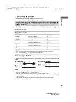
This section describes how to set up the receiver before using it.
Specific connection procedures for your output devices are explained in steps 1a, 1b, and 1c. Refer to
the table below to proceed.
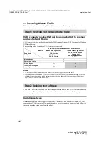
Output device list
1)
When your device comes with jacks such as digital optical output or digital coaxial output jacks.
2)
When you device only comes with jacks such as audio out L/R jacks.
Before you get started
The connection diagrams on the subsequent pages assume the use of the following optional cables (
to
).
A
Audio cable
White (L)
Red (R)
B
Video cable
Yellow
C
Optical digital cable
D
Coaxial digital cable
Notes
• Turn off the power to all components before making any connections.
• Be sure to make connections firmly to avoid hum and noise.
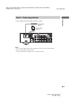
• Connect the yellow connector of the video cable to the VIDEO IN jack of the receiver.
• Connect the red connector of the audio cable to the AUDIO IN R jack, and the white connector to the AUDIO IN
L jack of the receiver
• When connecting optical digital cables, insert the cable plugs straight in until they click into place.
• Do not bend or tie optical digital cables.
Step 1: Verifying the connection procedure for your type of
output devices
Output device
Pages
DVD player
With digital output jacks
1)
With analogue output jacks only
2)
Television
Satellite tuner
With digital output jacks
1)
With analogue output jacks only
2)
MD deck/tape deck
With digital output jacks
1)
With analogue output jacks only
2)
VCR
Antennae


