background image

FL DISPLAY/KEY LED TEST MODE

Press the REPEAT, ENTER/NEXT and SURROUND buttons
simultaneously.
1.

All FL segments and all LEDs turn on.

2.

To access the microprocessor information, press the P FILE
key.  Each pressing of the P FILE key advances the display on
the FL tube in the following sequence.

3. To check the encoder, press the MUSIC key.  The following display
appears on the FL tube.
"K

0

J

0

V

0"

The number after K indicates the number of times that the key is
pressed.  The key which was pressed in the past, is not counted.
The key which is pressed hereafter is counted.  Pressing any key
increases the number after K.

The number after J indicates the number of rotations that the JOG
dial is rotated.  Turning the JOG dial clockwise increases the number
after J.  Turning the JOG dial counter-clockwise decreases the
number after J.

The number after V indicates the number of rotations that the
VOLUME dial is rotated.  Turning the VOLUME dial clockwise
increases the number after V.  Turning the VOLUME dial counter-
clockwise decreases the number after V.

To exit this mode, perform the "Cold Reset" (reset clearing memory)
as described below.

GENERAL TEST  MODE
(INCLUDING AMPLIFIER AND TUNER)

Press the REPEAT, ENTER/NEXT and CLOCK TIMER SET
buttons simultaneously while the main power is on.
1.

Sound volume display segment starts blinking.

2.

The tuning enters the PRESET mode.

3.

Rotating the VOLUME control clockwise increases the volume
level to maximum.
Rotating the VOLUME control counter-clockwise decreases
the volume level to minimum.

4.

Pressing the MUSIC key decreases the equalizer curve to
minimum and "EQ CHECK" appears on the display.
Pressing the MOVIE key increases the equalizer curve to
maximum.
Pressing the GAME key makes the equalizer curve flat.

5.

Pressing any of the DBFB, GROOVE or SURROUND key
disappears "EQ CHECK" on the display.

To exit this mode, perform the "Cold Reset" (reset clearing memory)
as described below.

SECTION 2

TEST MODE

AGING MODE

1.

CD aging mode
To execute the CD aging, set the three discs to the CD tray and
set the function to CD. REPEAT, ENTER/NEXT and LOOP
buttons simultaneously. The CD aging mode starts and the disc
calendar starts blinking.

2.

Tape aging mode
To execute the tape aging, set the two tapes to the tape A and B
drives.  Set the function to TAPE.  Press the REPEAT,  ENTER/
NEXT and LOOP buttons simultaneously. Press the A forward
key to start the tape aging mode.  "AGING" appears on the
display.

CD SERVICE MODE

Turn on the main power. Press the REPEAT, ENTER/NEXT and
KARAOKE PON/MPX buttons simultaneously.
VACS toggles between ON and OFF.

VACS LEVEL DISPLAY

Turn on the main power.  Press the EDIT, ENTER/NEXT and
KARAOKE PON/MPX buttons simultaneously.
VACS level appears on the display.

CD SHIP MODE

Turn on the main power. Press the PLAY MODE and POWER
buttons simultaneously.
The main power is turned off and LOCK appears on the display.

TUNER STEP CHANGE

Turn on the main power.  Set the function to TUNER.  Select MW
band from the present tuning.
Turn off the main power.  Press the ENTER/NEXT and POWER
buttons simultaneously.  The main power is turned on and the
changed step appears on the display.

MD/VIDEO 1 FUNCTION CHANGE

Press the FUNCTION and POWER buttons simultaneously while
the main power is off.  When the function is set to VIDEO 1, the
function is changed to MD and MD appears on the display.
When the function is set to MD, the function is changed to VIDEO
1 and VIDEO 1 appears on the display.

COLD RESET (Reset which clears memory.)

Press the REPEAT, ENTER/NEXT and DISPLAY buttons
simultaneously at any time.  The system is reset while clearing
memory.

HOT RESET
(Reset which does not clear memory.)

Press the REPEAT, ENTER/NEXT and  TIMER SELECT buttons
simultaneously at any time.  The system is reset without clearing
memory.

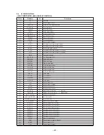
STR microprocessor version number

HCD microprocessor version number

VCD microprocessor version number (VCD model only)

Model name

Destination 

3-1.

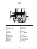
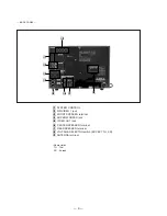
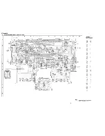
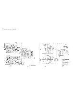
CIRCUIT BOARDS LOCATION

SECTION 3

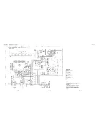
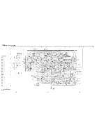
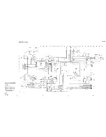
DIAGRAMS

PRI BOARD

SEC BOARD

PANEL BOARD

AVIN BOARD

JOG BOARD

VOLUME BOARD

MIC ECHO BOARD

MAIN BOARD

SUR BOARD

 AMP-A BOARD

ENCAPSULATED
COMPONENT

— 5 —

— 6 —

SUPPLY POWER BOARD

SURROUND
AMP BOARD

KEY-CON BOARD

Summary of Contents for STR-V7700

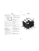
Page 1: ...cks voltage 250 mV impedance 1 kilo ohm PHONES stereo phone jack accepts headphones of 8 ohms or more FRONT SPEAKER accepts impedance of 6 to 16 ohms CENTER SPEAKER accepts impedance of 8 to 16 ohms REAR SPEAKER accepts impedance of 8 to 16 ohms SUPER WOOFER Voltage 1 V impedance 1 kilo ohm Video section Inputs AV INPUT VIDEO phono jack 1 Vp p 75 ohms VIDEO IN phono jack 1 Vp p 75 ohms Outputs MON...

Page 2: ...ing Board and Schematic Diagram Power Section 26 3 9 IC Pin Function 29 3 10 IC Block Diagrams 31 4 EXPLODED VIEWS 4 1 Main Section 33 4 2 Panel Section 34 5 ELECTRICAL PARTS LIST 35 SAFETY RELATED COMPONENT WARNING COMPONENTS IDENTIFIED BY MARK OR DOTTED LINEWITH MARK ON THE SCHEMATIC DIAGRAMS AND IN THE PARTS LIST ARE CRITICAL TO SAFE OPERATION REPLACE THESE COMPONENTS WITH SONY PARTS WHOSE PART...

Page 3: ... button FUNCTION button MIC LEVEL ECHO VOL MIX MIC 1 jack MIX MIC 2 jack PHONES jack ª EDIT button º PLAY MODE button 1 ALL DISCS button REPEAT button HIGH FREQ button ENTER NEXT button MULTI JOG STATION dial LOW FREQ button MEMORY button TUNING MODE button ª FLASH button º LOOP button WAVE button AV INPUT jack CLOCK TIMER SET button TIMER SELECT button KEY CONTROL button KEY CONTROL n button DOLB...

Page 4: ...TEM CONTROL MD VIDEO 1 jack FRONT SPEAKER terminal SUPER WOOFER jack VIDEO OUT jack CENTER SPEAKER terminal REAR SPEAKER terminal VOLTAGE SELECTOR switch EXCEPT TH KR ª ANTENNA terminal Abbreviation TH Thai KR Korean ª ...

Page 5: ...xecute the CD aging set the three discs to the CD tray and set the function to CD REPEAT ENTER NEXT and LOOP buttons simultaneously The CD aging mode starts and the disc calendar starts blinking 2 Tape aging mode To execute the tape aging set the two tapes to the tape A and B drives Set the function to TAPE Press the REPEAT ENTER NEXT and LOOP buttons simultaneously Press theA forward key to start...

Page 6: ......

Page 7: ......

Page 8: ......

Page 9: ......

Page 10: ......

Page 11: ......

Page 12: ......

Page 13: ...er input Volum encoder input JOG dial encoder input AUB input 12C clock I O 12C data I O AUB output Power supply 5V Power supply Ground Latch output to IC105 Latch output to IC2002 Mute output to transistor L Mute ON DBFB level control output L DBFB HIGH Latch output to IC6003 H Key con ON L SP relay ON PRO LOGIC RELAY output Key data input A D converter Key data input A D converter Key data input...

Page 14: ...O O O O O O O O O Description H MUTE L Signal Receiving Not used Pin Name FL 1G FL 2G FL 3G FL 4G FL 5G FL 6G FL 7G FL 8G FL 9G FL 10G FL 11G FL 12G FL 13G FL 14G FL P1 FL P2 FL P3 FL P4 FL P5 FL P6 FL P7 FL P8 FL P9 FL P10 FL P11 FL P12 FL P13 FL P14 FL P15 FL P16 FL P17 FL P18 FL P19 FL P20 FL P21 FL P22 FL P23 FL P24 FL P25 FL P26 FL P27 FL P28 FL P29 FL P30 FL P31 FL P32 FL P33 FL P34 ST MUTE ...

Page 15: ...A V CC L OUT R OUT S OUT C OUT ENABLE OSC1 CMODE CAP C TRIM DC CUT R BPF1 R BPF2 R BPF3 DC CUT DC CUT L R RECT L R RECT VCS TH VCS 1 VCS 2 BPF1 BPF2 VREF S CH DC OUT C CH DC OUT L CH DC OUT R CH DC OUT VREF L BPF1 L BPF2 L BPF3 DC CUT DC CUT R RECT L RECT VLR TH VLR 1 VLR 2 1 5 6 20 19 18 17 16 15 14 13 21 22 23 24 2 3 4 7 8 9 10 12 11 DEC IN FILTER 40kHz VDD ADM CONT SRAM ADM OUT FILTER 7k 5k B N...

Page 16: ... IC850 µPC1237HA SBAND GRAPHIC EQUALIZER SBAND GRAPHIC EQUALIZER U CON INTER FACE 1 2 3 4 5 6 7 8 9 10 20 19 18 17 16 15 14 13 12 11 21 22 23 24 64 63 62 61 60 59 58 57 56 55 45 46 47 48 49 50 51 52 53 54 44 43 42 41 25 26 27 28 29 30 31 32 33 34 40 39 38 37 36 35 80 79 78 77 76 75 74 73 72 71 65 66 67 68 69 70 KEY OUT1 NC3 REC 1A REC 1B REC 1C NC4 F1 F1 F1 O1 F1 IN1 F2 F1 F2 O1 F2 IN1 F3 F1 F3 O1...

Page 17: ... BACK CH 8 4 991 361 61 PANEL VCD BACK TH 8 4 991 361 71 PANEL VCD BACK IA 8 4 991 361 81 PANEL VCD BACK KR 9 A 4403 282 A MAIN BOARD COMPLETE MY SP KR CH 9 A 4403 694 A MAIN BOARD COMPLETE IA 9 A 4403 704 A MAIN BOARD COMPLETE TH 10 4 970 381 11 FOOT REAR 11 3 703 244 00 BUSHING 2104 CORD TH IA 11 3 703 571 11 BUSHING S 4516 CORD MY SP KR CH 12 1 751 326 31 CORD POWER TH 12 1 777 071 21 CORD POWE...

Page 18: ...3 4 984 085 01 SPRING ENTER COMPRESSION 64 A 4403 285 A PANEL BOARD COMPLETE MY SP KR CH 64 A 4403 701 A PANEL BOARD COMPLETE IA 64 A 4403 708 A PANEL BOARD COMPLETE TH 65 4 951 620 01 SCREW 2 6X8 BVTP 66 A 4403 207 A MIC ECHO BOARD COMPLETE MY SP KR CH 66 A 4403 689 A MIC ECHO BOARD COMPLETE IA 66 A 4403 706 A MIC ECHO BOARD COMPLETE TH 67 4 991 327 01 KNOB CONTROL FL501 1 517 618 11 INDICATOR TU...
Page 19: ...5 11 FILM 0 068uF 5 50V CONNECTOR CN902 1 564 524 11 PLUG CONNECTOR 9P DIODE D903 8 719 987 63 DIODE 1N4148M D953 8 719 987 63 DIODE 1N4148M IC IC901 8 749 921 04 IC STK 4211MK 2 TRANSISTOR Q901 8 729 900 80 TRANSISTOR DTC114ES Q902 8 729 140 84 TRANSISTOR 2SC1841 PAFAEA Q952 8 729 140 84 TRANSISTOR 2SC1841 PAFAEA RESISTOR R901 1 249 417 11 CARBON 1K 5 1 4W F R902 1 249 437 11 CARBON 47K 5 1 4W R9...

Page 20: ...ELECT 10uF 20 50V C6102 1 162 290 31 CERAMIC 470PF 10 50V C6103 1 162 291 31 CERAMIC 560PF 10 50V C6104 1 162 600 11 CERAMIC 0 0047uF 30 16V C6106 1 162 294 31 CERAMIC 0 001uF 10 50V C6107 1 164 159 11 CERAMIC 0 1uF 50V C6108 1 164 159 11 CERAMIC 0 1uF 50V C6109 1 136 495 11 FILM 0 068uF 5 50V C6110 1 136 495 11 FILM 0 068uF 5 50V C6111 1 136 495 11 FILM 0 068uF 5 50V C6112 1 162 286 31 CERAMIC 22...

Page 21: ... 130 479 00 MYLAR 0 0047uF 5 50V C161 1 130 479 00 MYLAR 0 0047uF 5 50V C162 1 126 964 11 ELECT 10uF 20 50V C163 1 126 963 11 ELECT 4 7uF 20 50V C164 1 136 166 00 FILM 0 12uF 5 50V EXCEPT TH C164 1 136 167 00 FILM 0 15uF 5 50V TH C165 1 136 166 00 FILM 0 12uF 5 50V EXCEPT TH C165 1 136 167 00 FILM 0 15uF 5 50V TH C166 1 126 961 11 ELECT 2 2uF 20 50V C171 1 162 303 11 CERAMIC 0 0033uF 30 16V TH C18...

Page 22: ... 336 11 SOCKET CONNECTOR PC BOARD 14P CN106 1 774 336 11 SOCKET CONNECTOR PC BOARD 14P CN811 1 569 498 11 SOCKET CONNECTOR 12P CN2003 1 691 765 41 PLUG MICRO CONNECTOR 3P CN6000 1 573 845 11 CONNECTOR BOARD TO BOARD 13P CN6002 1 568 937 11 PIN CONNECTOR 10P CN6003 1 770 722 11 CONNECTOR BOARD TO BOARD 6P CONNECTOR CNP701 1 764 017 21 HOUSING CONNECTOR PC BOARD 17P SYSTEM CONTROL DIODE D101 8 719 9...

Page 23: ... 22K 5 1 4W EXCEPT IA R123 1 249 431 11 CARBON 15K 5 1 4W IA R124 1 249 437 11 CARBON 47K 5 1 4W R125 1 247 807 31 CARBON 100 5 1 4W R126 1 249 429 11 CARBON 10K 5 1 4W R129 1 247 887 00 CARBON 220K 5 1 4W R137 1 247 807 31 CARBON 100 5 1 4W R138 1 247 807 31 CARBON 100 5 1 4W R139 1 247 807 31 CARBON 100 5 1 4W R140 1 247 807 31 CARBON 100 5 1 4W R141 1 247 807 31 CARBON 100 5 1 4W R142 1 247 807...

Page 24: ...5 1 4W R2004 1 249 429 11 CARBON 10K 5 1 4W R2005 1 249 441 11 CARBON 100K 5 1 4W R2006 1 249 421 11 CARBON 2 2K 5 1 4W F R2007 1 249 425 11 CARBON 4 7K 5 1 4W F R2010 1 249 441 11 CARBON 100K 5 1 4W R2030 1 215 863 11 METAL OXIDE 100 5 1W F R2051 1 249 417 11 CARBON 1K 5 1 4W F R2052 1 249 441 11 CARBON 100K 5 1 4W R2053 1 249 431 11 CARBON 15K 5 1 4W R2054 1 249 429 11 CARBON 10K 5 1 4W R2055 1 ...

Page 25: ... 1 249 417 11 CARBON 1K 5 1 4W F R6018 1 247 881 00 CARBON 120K 5 1 4W R6019 1 247 807 31 CARBON 100 5 1 4W R6030 1 247 895 00 CARBON 470K 5 1 4W R6201 1 249 419 11 CARBON 1 5K 5 1 4W F R6202 1 249 418 11 CARBON 1 2K 5 1 4W F R6251 1 249 419 11 CARBON 1 5K 5 1 4W F R6252 1 249 418 11 CARBON 1 2K 5 1 4W F VARIABLE RESISTOR RV6001 1 225 511 11 RES VAR CARBON 50K 50K MIC LEVEL ECHO LEVEL A 4403 285 A...

Page 26: ...483 31 IC TMP87CM75F 6623 IC502 8 759 332 18 IC GP1U27XB IC503 8 759 165 82 IC PST600E T IC504 8 759 372 64 IC M66313FP 200C COIL L502 1 408 074 00 INDUCTOR 56uH TRANSISTOR Q501 8 729 620 05 TRANSISTOR 2SC2603 EF Q502 8 729 422 57 TRANSISTOR UN4111 Q503 8 729 620 05 TRANSISTOR 2SC2603 EF Q504 8 729 422 57 TRANSISTOR UN4111 Q505 8 729 422 57 TRANSISTOR UN4111 Q506 8 729 422 57 TRANSISTOR UN4111 Q50...

Page 27: ... 1 249 435 11 CARBON 33K 5 1 4W R631 1 249 435 11 CARBON 33K 5 1 4W R632 1 249 437 11 CARBON 47K 5 1 4W R633 1 247 903 00 CARBON 1M 5 1 4W R634 1 249 437 11 CARBON 47K 5 1 4W R635 1 247 903 00 CARBON 1M 5 1 4W R636 1 249 435 11 CARBON 33K 5 1 4W R637 1 249 429 11 CARBON 10K 5 1 4W R638 1 249 437 11 CARBON 47K 5 1 4W R639 1 249 437 11 CARBON 47K 5 1 4W R640 1 247 903 00 CARBON 1M 5 1 4W R641 1 247 ...

Page 28: ... 0 1uF 5 50V CONNECTOR CN4001 1 564 522 11 PLUG CONNECTOR 7P DIODE D4003 8 719 987 63 DIODE 1N4148M D4053 8 719 987 63 DIODE 1N4148M IC IC4001 8 749 900 96 IC STK 4142MK2 TRANSISTOR Q4002 8 729 140 84 TRANSISTOR 2SC1841 PAFAEA Q4052 8 729 140 84 TRANSISTOR 2SC1841 PAFAEA RESISTOR R4001 1 249 417 11 CARBON 1K 5 1 4W F R4002 1 249 437 11 CARBON 47K 5 1 4W R4003 1 249 413 11 CARBON 470 5 1 4W F R4004...

Page 29: ...BON 1 5K 5 1 4W F R821 1 249 419 11 CARBON 1 5K 5 1 4W F R830 1 216 446 00 METAL OXIDE 18 5 2W F EXCEPT TH R830 1 215 881 11 METAL OXIDE 15 5 2W F TH R831 1 216 446 00 METAL OXIDE 18 5 2W F EXCEPT TH R831 1 215 881 11 METAL OXIDE 15 5 2W F TH R832 1 216 446 00 METAL OXIDE 18 5 2W F EXCEPT TH R832 1 215 881 11 METAL OXIDE 15 5 2W F R833 1 216 446 00 METAL OXIDE 18 5 2W F EXCEPT TH R833 1 215 881 11...

Page 30: ... 46 STR V7700 Sony Corporation Home A V Products Company 9 920 960 11 97H16086 1 Printed in Japan 1997 8 Published by General Engineering Dept Shibaura ...

Page 31: ......

Reviews: