— 2 —
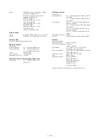
Output
MD/VIDEO 1 OUT (phono jacks): voltage
450/250mV, impedance 1k
Ω
PHONES (stereo phone jack): accepts
headphones of 8
Ω
or more.
FRONT SPEAKER:
accepts impedance of 6 to 16
Ω
CENTER SPEAKER:
accepts impedance of 8 to 16
Ω
REAR SPEAKER:
accepts impedance of 8 to 16
Ω
SUPER WOOFER:
Voltage 1V, impedance 1k
Ω
Video section
Inputs
AV INPUT VIDEO (phone jack): 1Vp-p, 75
Ω
Outputs
MONITOR OUT (phone jack): 1Vp-p, 75
Ω
Tuner section
FM stereo, FM/AM superheterodyne tuner
FM tuner section
Tuning range
3 band type model
87.5 – 108.0MHz (50kHz step)
4 band type model
65.0 – 74.0MHz (10kHz step)
87.5 – 108.0MHz (50kHz step)
Aerial
FM lead aerial
Aerial terminals
75
Ω
unbalanced
Intermediate frequency
10.7MHz
UKV tuner section (4 band type model only)
Tuning range
65.0 – 74.0MHz (10kHz step)
Polar Stereo
AM tuner section
Tuning range
Australian model:
531 – 1,602kHz (with the AM tuning interval
set at 9kHz)
530 – 1,710kHz (with the AM tuning interval
set at 10kHz)
Other models:
MW: 531 – 1,602kHz (with the MW tuning
interval set at 9kHz)
530 – 1,710kHz (with the MW tuning interval
set at 10kHz)
SW: 5.95 – 17.90MHz (with the SW tuning
interval set at 5kHz)
LW: 153 – 279kHz (with the interval set at
3kHz)
Intermediate frequency
450kHz
Antenna
AM loop antenna External antenna terminal
General
Power requirements
Australian models:
240V AC, 50/60Hz
AEP, UK, East European, CIS models:
230V AC, 50/60Hz
Other models:
120V or 220V or 230 – 240, 50/60Hz
Adjustable with voltage selector
Power consumption
270W (AEP, UK, East European, CIS models)
300W (Other models)
Dimensions (w/h/d)
Approx. 288
×
205
×
375mm
Mass
Approx. 8.8kg
Supplied accessories:
AM loop antenna (1)
Remote RM-SR77 (1)
Size AA (R6) batteries (2)
FM lead antenna (1)
Speaker cords (5)
Front speaker pads (8)
Design and specifications are subject to change without notice.
Summary of Contents for STR-W777
Page 26: ...5 10 SCHEMATIC DIAGRAM AV MIC SECTION Refer to page 58 for IC Block Diagrams 35 ...
Page 27: ...5 11 Printed Wiring Board AV MIC Section Refer to page 12 for Circuit Boards Location 36 ...
Page 28: ...STR W777 5 12 SCHEMATIC DIAGRAM POWER AMP SECTION 37 38 ...
Page 30: ...STR W777 5 14 SCHEMATIC DIAGRAM DISPLAY SECTION Refer to page 59 for IC Block Diagrams 41 42 ...
Page 34: ...STR W777 5 18 SCHEMATIC DIAGRAM SURROUND AMP SECTION 49 50 ...
Page 37: ... 55 5 21 SCHEMATIC DIAGRAM TRANS SECTION STR W777 ...


