background image

SDM-S81R

US Model

Canadian Model

AEP Model

Chinese Model

TFT LCD COLOR COMPUTER DISPLAY

SPECIFICATIONS

SERVICE MANUAL

LCD panel

Panel type: a-Si TFT Active Matrix
Picture size: 18.1 inch

Input signal format

RGB operating frequency*
Horizontal: 28 – 80 kHz
Vertical: 48 – 75 Hz

Resolution

Horizontal: Max.1280 dots
Vertical: Max.1024 lines

Input signal levels

RGB video signal

0.7 Vp-p, 75 

, positive

SYNC signal

TTL level, 2.2 k

,

positive or negative
(Separate horizontal and vertical,
or composite sync)
0.3 Vp-p, 75

, negative

(Sync on green)

Power requirements

100 – 240 V, 50 – 60 Hz,
Max. 1.0 A

Power consumption

Max. 55 W

Operating temperature 5 – 35 

°

C

Dimensions (width/height/depth)

Display (upright):

Approx. 439 

x

 416 

x

 233 mm

(17 

3

/

8


x

 16 

1

/

2


x

 9 

1

/

4

 inches)

(with stand)
Approx. 439 

x

 357 

x

 70 mm

(17 

3

/

8


x

 14 

1

/

8


x

 2 

7

/

8

 inches)

(without stand)

Mass

Approx. 6.7 kg (14 lb 12 oz) (with stand)
Approx. 5.4 kg (11 lb 14 oz)
(without stand)

Plug & Play

DDC2B

* Recommended horizontal and vertical timing condition

• Horizontal sync width duty should be more than 4.8% of total
  horizontal time or 0.8 

µ

sec, whichever is larger.

• Horizontal blanking width should be more than 2.5 

µ

sec.

• Vertical blanking width should be more than 450 

µ

sec.

Design and specifications are subject to change without notice.

Summary of Contents for StylePro SDM-S71R

Page 1: ...reen Power requirements 100 240 V 50 60 Hz Max 1 0 A Power consumption Max 55 W Operating temperature 5 35 C Dimensions width height depth Display upright Approx 439 x 416 x 233 mm 17 3 8 x 16 1 2 x 9 1 4 inches with stand Approx 439 x 357 x 70 mm 17 3 8 x 14 1 8 x 2 7 8 inches without stand Mass Approx 6 7 kg 14 lb 12 oz with stand Approx 5 4 kg 11 lb 14 oz without stand Plug Play DDC2B Recommend...

Page 2: ... your instruments are accurate be suspicious of your HV meter if sets always have low HV 8 Check the antenna terminals metal trim metallized knobs screws and all other exposed metal parts for AC Leakage Check leakage as described right SAFETY CHECK OUT LEAKAGE TEST The AC leakage from any exposed metal part to earth ground and from all exposed metal parts to any exposed metal part having a return ...

Page 3: ...NTIFIED INTHIS MANUAL FOLLOW THESE PROCEDURES WHENEVER CRITI CAL COMPONENTS ARE REPLACED OR IMPROPER OPERA TION IS SUSPECTED AVERTISSEMENT NE JAMAIS METTRE SOUS TENSION QUAND LA BOBINE DEDEMAGNETISATION EST ENLEVÉE ATTENTION AUX COMPOSANTS RELATIFS À LA SÉCURITÉ LES COMPOSANTS IDENTIFIÉS PAR UNE TRAME ET UNE MARQUE 0 SONT CRITIQUES POUR LA SÉCURITÉ NE LES REMPLACER QUE PAR UNE PIÈCE PORTANT LE NUM...

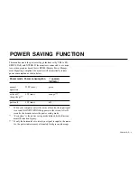
Page 4: ...ion 1 power indicator normal 55 W max green operation active off 3 W max orange deep sleep power off 2 W max off When your computer enters the active off mode the input signal is cut and NO INPUT SIGNAL appears on the screen After 20 seconds the monitor enters the power saving mode deep sleep is the power saving mode defined by the Environ mental Protection Agency If only the horizontal or vertica...

Page 5: ...tor s frequency range horizontal 28 80 kHz vertical 48 75 Hz Consequently the firdt time the monitor receives input signals that do not match one of the factory preset modes the monitor may take a longer time than normal for displaying the picture on the screen This adjustment data is automatically stored in memory so that next time the monitor will function in the same way as when the monitor rec...

Page 6: ...G Mount 1 3 1 4 A Mount 1 4 1 5 TFT Panell 1 5 2 ADJUSTMENTS 2 1 Functional Adjustment 2 1 2 2 Timing Specification 2 2 2 3 White Balance Adjustment 2 3 Section Titel Page 3 DIAGRAMS 3 1 Circuit Boards Location 3 1 4 EXPLODED VIEWS 4 1 Chassis 4 2 4 2 Packing Materials 4 3 Section Titel Page ...

Page 7: ...SDM S81R E 1 1 SECTION 1 DISASSEMBLY 1 1 CABINET ASSEMBLY 1 Four screws PVTP 3x16 2 Cabinet assembly 3 Chassis assembly bezel assembly ...

Page 8: ...SDM S81R E 1 2 1 2 H MOUNT 2 Screw BVTP 3x8 2 Screw BVTP 3x8 3 H board 1 P1 ...

Page 9: ...SDM S81R E 1 3 1 3 G MOUNT 1 Two screws PTT 3x4 1 Three screws PTT 3x4 1 Two screws PTT 3x4 1 Screw PTT 3x4 4 Three screws PTTWH 3x6 2 Rear shield 3 Conector inlet 3 CN2 5 G board 3 CN3 3 CN1 ...

Page 10: ...R E 1 4 1 4 A BOARD 1 Two screws PTT 3x4 1 Three screws PTT 3x4 4 Two screws PTT 3x4 1 Two screws PTT 3x4 1 Screw PTT 3x4 4 Two screws PTT 3x4 2 Rear shield 3 J710 5 A board 3 J705 3 J702 4Two connector screws ...

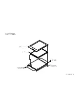
Page 11: ...SDM S81R E 1 5 1 5 TFT PANEL 3 Two screws FTT 3x5 1 Two screws BVTP 3x16 3 Two screws FTT 3x5 4 TFT panel 2 Bezel assembly ...

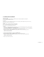
Page 12: ...s memory resets BACKLIGHT CONTRAST BRIGHTNESS PHASE PITCH CENTER COLOR USER ADJUSTMENT COLOR GAMMA MENU POSITION POWERSAVE LANGUAGE MENU LOCK to default values Also clears Aging Mode After executing this command be sure to put AC power cord out and in to set the default values Refleshing is required Aging mode On the stand by mode press 1 key while pressing R key The monitor goes into the no signa...

Page 13: ... BLK 0 656 42 V FP 0 016 1 V SYNC 0 047 3 V BP 0 594 38 V ACTIV 16 005 1024 1280 1024 X 108 000 MHZ 63 981 kHz usec dots 15 630 1688 3 778 408 0 444 48 1 037 112 2 296 248 11 852 1280 60 020 Hz msec lines 16 661 1066 0 656 42 0 016 1 0 047 3 0 594 38 16 005 1024 SYNC INT G EXT H V POLARITY YES P P EXT CS POLARITY Serration NO NO NO SYNC LEVEL TTL V VIDEO VIDEO LEVEL 0 730 Vp p SET UP 0 V OTHERS IN...

Page 14: ... timing all white signal At this time check each R G and B signal output is 0 73Vp p 75ohm teminated Select and execute WHITE BALANCE command in service menu 2 Switch the signal to the 35IRE all gray select COLORTEMP 9300K The signal output level should be 0 245V at 75ohm terminated 3 Put the SUB CONTRAST R G B data in WHITE BALANCE caribration down 25 degrees evenly 4 Adjust the R G and B data of...

Page 15: ...SDM S81R E 3 1 SECTION 3 DIAGRAMS 3 1 CIRCUIT BOARDS LOCATION G board H board A board ...

Page 16: ... a collation number in the remark column Items marked are not stocked since they are seldom required for routine service Some delay should be anticipated when ordering these items The components identified 0 0 marked are critical for safety Replace only with the part number specified Les composants identifiés par la marque sont critiques pour la sécurité Ne les remplacer que par une pièce portant ...

Page 17: ...6 X 4041 334 1 STAND ASSY WHITE 6 X 4041 337 1 STAND ASSY BLACK 7 4 094 144 01 COVER REAR WHITE 7 4 094 144 11 COVER REAR BLACK 8 4 094 143 01 CABINET WHITE 8 4 094 143 11 CABINET BLACK 9 1 900 273 37 CONNECTOR ASSY 10 A 1404 874 A I BOARD COMPLETE 1 8 2 3 9 5 PTT3 N 4 PTT3 N 4 PTT3 N 4 PTT3 N 4 PTT3 N 4 PTT3 N 4 FTT2 6 N 5 FTT2 6 N 5 PSW4 N 10 BVTP3 N 16 P4 N 10 PTP3 N 8 PTT 3 N 4 PTT 3 N 4 PTT 3...

Page 18: ... 53 55 56 57 58 51 54 REF NO PART NO DESCRIPTION REMARK 51 4 093 179 01 INDIVIDUAL CARTON WHITE 51 4 093 180 01 INDIVIDUAL CARTON BLACK 52 4 093 698 01 CUSHION L AEP 52 4 094 151 01 CUSHION L UC CH 53 4 093 697 01 CUSHION R AEP 53 4 094 150 01 CUSHION R UC CH 54 4 093 696 01 BAG 1050X900 POLY 55 1 827 110 11 CABLE D SUB 56 0 1 827 118 11 POWER SUPPLY CORD SET UC 56 0 1 827 120 11 POWER SUPPLY CORD...

Page 19: ...9 978 766 01 English 2003CL02 Data Made in Japan 2003 3 SDM S81R E 5 1 ...

Reviews: