3-3(E)
SX-M700
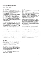
3-2-2. Audio Block
SX-M700
The audio block of the SX-M700 has the following basic
functions.
.
Receiving the audio signal from chairman and delegate units,
the audio block outputs these signals to the simultaneous
interpreter’s unit as the original language ORG signal.
.
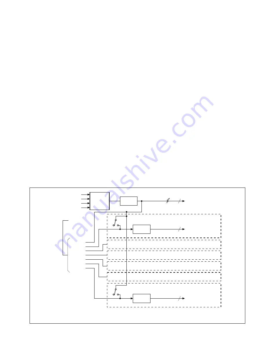
The ORG signal and the maximum six languages (CH-1 to
CH-6) which are translated by the simultaneous interpreter’s
units totaling seven channel audio signals are output to the
chairman and delegate units from the SX-M700.
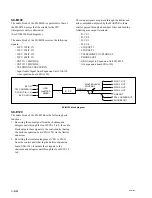
(See SX-M700 block diagram.)
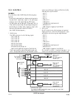
1. ORG System
The ORG system receives the following signals:
.
D/CU 1 MIC IN
.
D/CU 2 MIC IN
.
D/CU 3 MIC IN
.
D/CU 4 MIC IN
.
EXT IN 1 MIC/LINE
.
EXT IN 2 MIC/LINE
.
TELEPHONE COUPLER IN
.
Input Audio Signal from Expansion Unit SX-E120
These input signals are passed through the limiter and
mixer, are amplitude-adjusted by the MASTER volume
control, passed through a band-pass filter then feed the
following nine output terminals:
.
D/CU 1
.
D/CU 2
.
D/CU 3
.
D/CU 4
.
LINE OUT 1
.
LINE OUT 2
.
TELEPHONE COUPLER OUT
.
PHONES OUT
.
ORG Output to Expansion Unit SX-E120
2. IPU System
The IPU system receives the maximum six translated
languages (CH-1 to CH-6) from the interpreter’s units
and outputs to the following nine output terminals:
.
D/CU 1
.
D/CU 2
.
D/CU 3
.
D/CU 4
.
LINE OUT 1
.
LINE OUT 2
.
TELEPHONE COUPLER OUT
.
PHONES OUT
.
ORG Output to Expansion Unit SX-E120
The channels in which a translated language is not
turned on are switched automatically to the ORG signal.
EXT IN
TEL COUPLER IN
DCU MIC IN (1-4)
MASTER LEVEL
CONTROL 7
ORG OUT
ORG
LIMITTER
MIXER
B. P. F.
ORG OUT
CH1 IN
CH2 IN
CH3 IN
CH4 IN
CH5 IN
CH6 IN
CONNECT
to IPU
B. P. F.
B. P. F.
CH1 OUT
CH6 OUT
CH2 OUT
CH3 OUT
CH4 OUT
CH5 OUT
*
*
*
CH/ORG selector switch
The channels in which a translated language is not turned on are switched
automatically to the ORG signal.
D/CU 1-4 OUT
LINE OUT
TEL COUPLER OUT
PHONES OUT
D/CU1-4 OUT
LINE OUT
TEL COUPLER OUT
PHONES OUT
D/CU1-4 OUT
LINE OUT
TEL COUPLER OUT
PHONES OUT
7
7
EXP. UNIT IN
SX-M700 block diagram
Summary of Contents for SX-M100
Page 75: ...SX M700 6 12 TMP68301AFR 16 TOSHIBA http getMANUAL com ...
Page 111: ...8 2 8 2 SX M700 SX M700 AUDIO SX M700 BLOCK SX M700 BLOCK AUDIO BLOCK ...
Page 112: ...8 3 8 3 SX M700 SX M100 BLOCK SX M100 BLOCK SX M100 AUDIO AUDIO BLOCK ...
Page 113: ...8 4 8 4 SX M700 SX E120 DIGITAL SX E120 BLOCK SX E120 BLOCK DIGITAL BLOCK ...
Page 114: ...8 5 8 5 SX M700 SX E120 BLOCK SX E120 BLOCK SX E120 AUDIO AUDIO BLOCK ...
Page 115: ...8 6 8 6 SX M700 SX T100 AU 202 SX T100 BLOCK SX T100 BLOCK AU 202 BLOCK http getMANUAL com ...
Page 116: ...8 7 8 7 SX M700 SXA 120 BLOCK SXA 120 BLOCK SXA 120 AUDIO CPU 188 BLOCK ...
Page 120: ......
Page 126: ......
Page 128: ......
Page 130: ......
Page 132: ......
Page 136: ......

