4-6(E)
SX-M700
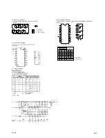
4-6. SX-T100 CHECK ITEMS
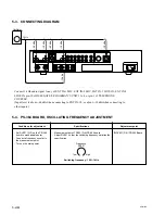
After completing repair, check the following:
1. Supply
+
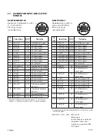
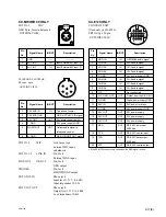
24 V to pin 3 of the input/output 6-pin
connector. Connect pin 4 to GND. Connect the input/
output 6-pin connector to the conference system and
turn on the main power.
2. Supply an audio signal of 1 kHz at
_
10 dBs between
pin 1 and pin 2 of the input/output 6-pin connector.
Confirm that the speaker emits an audio signal.
(pin 1: HOT)
3. Connect an audio meter of
_
10 dBs range between pin
5 and pin 6 of the input/output 6-pin connector. Speak
into the microphone and confirm that the meter pointer
deflects.
(pin 5: HOT)
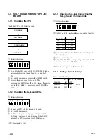
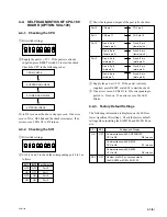
4-5. SELF DIAGNOSTICS OF SX-C700/
C100/D700/D100
1
Short the SL5 and 24 V.
2
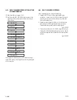
Each time the MIC ON/OFF button is pressed, the
operation of the audio circuit advances one step as
shown below.
The respective control system can be checked using a
single D/C unit by observing the results of operating the
above sequence.
1. Speaker ON
2. MIC ON
3. MIC OFF
4. Speaker atternuation ON
5. Speaker attenuation OFF
6. EP ATT ON
7. EP ATT OFF
9. Channel selector OFF
8. Channel selector ON
10. Speaker OFF
Summary of Contents for SX-M100
Page 75: ...SX M700 6 12 TMP68301AFR 16 TOSHIBA http getMANUAL com ...
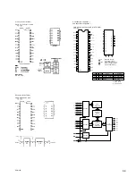
Page 111: ...8 2 8 2 SX M700 SX M700 AUDIO SX M700 BLOCK SX M700 BLOCK AUDIO BLOCK ...
Page 112: ...8 3 8 3 SX M700 SX M100 BLOCK SX M100 BLOCK SX M100 AUDIO AUDIO BLOCK ...
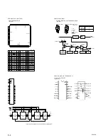
Page 113: ...8 4 8 4 SX M700 SX E120 DIGITAL SX E120 BLOCK SX E120 BLOCK DIGITAL BLOCK ...
Page 114: ...8 5 8 5 SX M700 SX E120 BLOCK SX E120 BLOCK SX E120 AUDIO AUDIO BLOCK ...
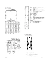
Page 115: ...8 6 8 6 SX M700 SX T100 AU 202 SX T100 BLOCK SX T100 BLOCK AU 202 BLOCK http getMANUAL com ...
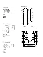
Page 116: ...8 7 8 7 SX M700 SXA 120 BLOCK SXA 120 BLOCK SXA 120 AUDIO CPU 188 BLOCK ...
Page 120: ......
Page 126: ......
Page 128: ......
Page 130: ......
Page 132: ......
Page 136: ......


