129
TA-DA9000ES
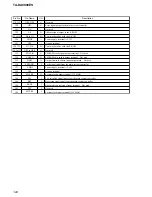
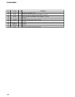
Pin No.
Pin Name
I/O
Description
43
V595-LAT
O
Serial data latch pulse output to the data decoder
44
VSS
—
Ground terminal
45
C595-LAT
O
Serial data latch pulse output to the data decoder
46
FUNCLAT
O
Serial data latch pulse output to the function switch
47
D.MIXLAT
O
Serial data latch pulse output to the function switch
48
VDLLAT
O
Serial data latch pulse output to the electrical volume
49
PRE.D.M.LAT
O
Serial data latch pulse output to the function switch
50
PREOUT VOL-LAT
O
Serial data latch pulse output to the electrical volume
51
A1OUT
O
SIRCS signal output for the CONTROL A1II
52
MD2
I
Model distination signal input from the sub system controller
53
MD1
I
Model distination signal input terminal Not used
54
MD0
I
Model distination signal input from the sub system controller
55
RSTX
I
System reset signal input terminal “L”: reset
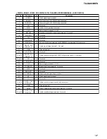
56
VCC
—
Power supply terminal (+3.3V)
57
X1
O
Main system clock output terminal (16.5 MHz)
58
X0
I
Main system clock input terminal (16.5 MHz)
59
VSS
—
Ground terminal
60
A1IN
I
SIRCS signal input for the CONTROL A1II
61
SIRCS IN
I
SIRCS signal input terminal
62
POWER SW
I
I/
1
key input terminal
63 to 67
MBUS-STS0 to
MBUS-STS4
I
M-BUS status input from the sub system controller
68
VCC
—
Power supply terminal (+3.3V)
69
RST TRG
O
Reset signal output terminal
70
END FLAG
O
End flag output to the sub system controller
71
A1-LAT
O
Serial data latch pulse signal output to the sub system controller
72
ILINK RST
O
System reset signal output to the I-link system controller “L”: reset
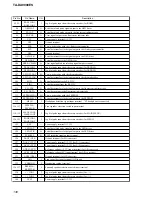
73, 74
FUNC1, FUNC2
I
Jog dial pulse input from the rotary encoder (for INPUT SELECTOR)
75, 76
POW-RY,
POW-RY2
O
Relay drive signal (for main power) output terminal “H”: relay on
77
VCC
—
Power supply terminal (+3.3V)
78
STOP
I
AC off detection signal input terminal
79
TUN-LAT
O
Serial data latch pulse signal output to the tuner unit (AEP model only)
80
TUN-TUNED
I
Tuned detection signal input from the tuner unit (AEP model only)
81
TUN-STEREO
I
FM stereo detection signal input from the tuner unit (AEP model only)
82
TUN-DO
I
Serial data input from the tuner unit (AEP model only)
83
SUB-RST
O
System reset signal output to the output controller “L”: reset
84
S-MUTE
O
System muting on/off control signal output terminal “H”: muting on
85
MIAN-CLK
O
Clock signal output to the output controller
86
SUB-U INFO2
I
Serial data input from the output controller
87
SUB-U INFO1
O
Serial data output to the output controller
88
BBSEL
O
Bass boost filter on/off selection signal output to the DC cut digital filter “L”: on
89
FSRATE
I
L/R sampling clock signal (44.1 kHz) input from the digital audio interface receiver, decimation
filter and i-link interface
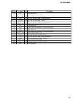
90, 91
VOL JOG1,
VOL JOG2
I
Jog dial pulse input from the rotary encoder (for MASTER VOLUME)


