background image

— 1 —

CPD-220GS

SPECIFICATIONS

Picture tube

Viewable image size

Resolution

Standard image area

0.25 mm aperture grill pitch

17 inches measured diagonally

90-degree deflection

Approx. 327 x 243 mm (w/h)

(12 

7/8

 x 9 

5/8 

 inches)

16.0" viewing image

Horizontal: Max. 1280 dots

Vertical: Max. 1024 lines

Approx. 312 x 234 mm (w/h)

(12 

3/8

 x 9 

1/4

inches)

Deflection frequency

Plug & Play

Speaker

Headphones output

Audio input

AC input voltage / current

Power consumption

Dimensions

Mass

Horizontal: 30 to 85 KHz

Vertical: 48 to120 Hz

DDC1/2B/2Bi, GTF

0.25W (monaural)

Stereo minijack, accepts impedance

of 8 

Ω 

or more

Stereo minijack

100 to 240 V, 50-60 Hz, 1.9 - 1.1 A

Max. 120W

406 x 432 x 420 mm (w/h/d)

(16 x 17

1/8

 x 16

5/8

 inches)

Approx. 18.0 kg (39 lb 11 oz)

SERVICE MANUAL

Design and specifications are subject to change without notice.

CPD-220GS

 COLOR  COMPUTER DISPLAY

CPD-220GS

US Model

Canadian Model

Chassis No. SCC-L23A-A

D-1H Plus

CHASSIS

Summary of Contents for Trinitron CPD-220GS

Page 1: ...y Plug Play Speaker Headphones output Audio input AC input voltage current Power consumption Dimensions Mass Horizontal 30 to 85 KHz Vertical 48 to120 Hz DDC1 2B 2Bi GTF 0 25W monaural Stereo minijack accepts impedance of 8 Ω or more Stereo minijack 100 to 240 V 50 60 Hz 1 9 1 1 A Max 120W 406 x 432 x 420 mm w h d 16 x 171 8 x 165 8 inches Approx 18 0 kg 39 lb 11 oz SERVICE MANUAL Design and speci...

Page 2: ...1024 x 768 1024 x 768 1024 x 768 1280 x 1024 Dot Clock MHz 25 175 36 000 28 322 49 500 56 250 57 283 78 750 80 000 94 500 135 000 HORIZONTAL Hor Freq kHz 31 469 43 269 31 469 46 875 53 674 49 725 60 024 60 241 68 677 79 976 H Total 31 778 23 111 31 777 21 333 18 631 20 111 16 660 16 600 14 561 12 504 H Blanking 6 356 5 333 6 355 5 172 4 409 5 586 3 657 3 800 3 725 3 022 H Front Porch 0 636 1 556 0...

Page 3: ...TIFIES DANS LE PRESENT MANUEL SUIVRE CES PROCEDURES LORS DE CHAQUE REMPLACEMENT DE COMPOSANTS CRITIQUES OU LORSQU UN MAUVAIS FONTIONNEMENT SUSPECTE 1 Check the area of your repair for unsoldered or poorly soldered connections Check the entire board surface for solder splashes and bridges 2 Check the interboard wiring to ensure that no wires are pinched or contact high wattage resistors 3 Check tha...

Page 4: ...Removal 14 3 SAFETY RELATED ADJUSTMENT 15 4 ADJUSTMENTS 16 5 DIAGRAMS 5 1 Block Diagram 19 5 2 Circuit Boards Location 22 5 3 Schematic Diagrams and Printed Wiring Boards 23 1 D Board Schematic Diagram 23 2 A Board Schematic Diagram 27 3 J Board Schematic Diagram 30 5 4 Semiconductors 31 6 EXPLODED VIEWS 6 1 Chassis 33 6 2 Packing Materials 34 7 ELECTRICAL PARTS LIST 35 ...

Page 5: ... detergent solution Do not use any type of abrasive pad scouring powder or solvent such as alcohol or benzine Do not rub touch or tap the surface of the screen with sharp or abrasive items such as a ballpoint pen or screwdriver This type of contact may result in a scratched picture tube Transportation When you transport this monitor for repair or shipment use the original carton and packing materi...

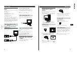
Page 6: ...ur needs Step 1 Connect the monitor to the computer Connecting to an IBM PC AT Macintosh or compatible computer With the computer switched off connect the video signal cable to the computer s video output to a power outlet Power cord supplied to AC IN to video output to video output Macintosh adapter supplied IBM PC AT or compatible computer Macintosh or compatible computer 7 Getting Started EN Ge...

Page 7: ...roducing the On screen Display System Most adjustments are made using the MENU OSD MENU OSD Press the MENU button to display the MENU OSD This MENU OSD contains links to the other OSDs described below 1 COLOR Displays the COLOR OSD for adjusting the color temperature 2 CENTER Displays the CENTER OSD for adjusting the centering of the picture 3 SCREEN Displays the SCREEN OSD for adjusting the verti...

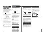
Page 8: ...ft MENU ROTATION GEOMETRY 26 11 Getting Started Customizing Your Monitor F EN ES C Using the ZOOM On screen Display The ZOOM settings allow you to enlarge or reduce the picture Once the setting is adjusted it will be stored in memory for the current input signal 1 Press the MENU button The MENU OSD appears 2 Press the and buttons to select ZOOM and press the MENU button again The ZOOM OSD appears ...

Page 9: ...0K 5000K COLOR VARIABLE 50 H CONVERGENCE SCREEN 26 13 Getting Started Customizing Your Monitor F EN ES C 4 Press the buttons to adjust the settings The OSD automatically disappears after about 30 seconds To close the OSD press the MENU button again To reset press the RESET button while the OSD is on The selected item is reset to the factory setting For H CONVERGENCE V CONVERGENCE CANCEL MOIRE MOIR...

Page 10: ...D H POSITION OPTION OSD V POSITION OPTION CONTROL LOCK OPTION OFF ON MANUAL DEGAUSS OPTION ON MANUAL DEGAUSS OPTION ON 15 Getting Started Customizing Your Monitor EN Resetting the Adjustments Resetting an adjustment item 1 Press the MENU and buttons to select the OSD containing the item you want to reset 2 Press the buttons to select the item you want to reset 3 Press the RESET button Resetting al...

Page 11: ...ear there is a potential monitor failure Inform your authorized Sony dealer of the monitor s condition Preset and User Modes The monitor has factory preset modes for the 10 most popular industry standards for true plug and play capability Recommended horizontal and vertical timing conditions Horizontal sync width duty should be 1 0 µsec of total horizontal time Horizontal blanking width should be ...

Page 12: ...function If the problem persists call your authorized Sony dealer from a location near your monitor Note the model name and the serial number of your monitor Also note the make and name of your video board 18 Additional Information Warning Messages If there is something wrong with the input signal one of the following messages appears The message disappears after about 30 seconds Additional Inform...

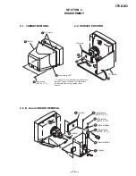
Page 13: ...4 x 16 Cabinet Two claws PUSH PUSH 2 Two audio jacks Caution To avoid breakage gently pull sides of cabinet out and over the audio jacks when removing cabinet from chassis Cable bracket Cable stopper Five screws BVTP 3 x 12 D board One screw BVTT 4 x 8 1 4 5 7 3 8 A board Two screws BVTP 3 x 12 6 J board 2 1 2 3 A board D board ...

Page 14: ...node cap to the metal chassis CRT shield or carbon painted on the CRT after removing the anode REMOVAL PROCEDURES Do not use sharp objects which may cause damage to the surface of the anode cap Do not squeeze the rubber covering too hard to avoid damaging the anode cap A material fitting called a shatter hook terminal is built into the rubber Do not force turn the foot of the rubber cover This may...

Page 15: ... shown below Standard voltage 185 0 3 0 VDC SECTION 3 SAFETY RELATED ADJUSTMENT Part Replaced RV501 Part Replaced D BOARD When replacing parts shown in the table below the following operational checks must be performed as a safety precaution against X ray emissions from the unit Allow the unit to warm up for one minute prior to checking the following conditions a HV Regulator Check 1 Input white c...

Page 16: ... coil to the specified position of CRT neck 5 Attach a landing adjuster sensor on the CRT 6 Using a landing checker adjust the DY position purity tilt of DY 7 Clamp the DY screw Clamping torque 22 2 kgcm 2 2 0 2 N m Convergence Rough Adjustment 1 Enter the white crosshatch signal 2 Adjust roughly the horizontal and vertical convergence at four pole magnet 3 Adjust roughly HMC and VMC at six pole m...

Page 17: ...sconvergence point in sequence H STAT 11 Digital Convergence Adjustment A Horizontal Convergence 2 7 0 4 6 1 5 3 9 8 12 11 V STAT B V STAT T CCV RT MCV RT XBV R MCV RB CCV RB CCV LB MCV LB XBV L MCV LT CCV LT Adjust each misconvergence point in sequence V STAT 8 Adjust V TILT with TLV VR TLV movement 9 Adjust Y CROSS with YCH VR YCH movement 10 Paint lock the four pole and six pole Mg VR Adjustmen...

Page 18: ... 18 CPD 220GS NOTES ...

Page 19: ... and adjustable resistors have characteristic curve B unless otherwise noted When replacing parts shown in the table below be sure to perform the safety related adjustment Part Replaced RV501 Part Replaced All voltages are in volts Readings are taken with a 10 ΜΩ digital multimeter Readings are taken with a color bar signal input Voltage variations may be noted due to normal production tolerances ...

Page 20: ...IC902 28 26 17 Q903 Q501 Q502 Q511 8P CN701 CY4 CY4 CY3 CY3 CY2 CY2 CY1 CY1 GND R OUT L OUT R IN L IN IC801 AUDIO AMP IC702 CONV AMP 6 4 9 16 CBLANK 7 49 53 S0 S4 24 15V 6 6 7 12V 5V 3 IC502 V IN H IN 46 GND DDCSCL DDCSDA RESET IC904 V DRIVE DA1 2 5 2 H OUT V DEF 12 Q505 Q504 CONV CONTROL IC701 4 33 PCI Q521 BUFFER 18 PB1 7P HSYNC VSOUT CSYNC BPCLP SHRP1 CBLK NC HOSTGND IICSCL GND IICSDA 3 1 IC006...

Page 21: ...IP 100 1 2W RC 75 RN CP 10k CHIP 6 8k CHIP 1M CHIP 100 1 2W RC 0 1 25V B CHIP 0 1 25V B CHIP 0 1 25V B CHIP 0 1 25V B CHIP 0 1 25V B CHIP 0 1 25V B CHIP 0 1 25V B CHIP 0 1 25V B CHIP 0 1 25V B CHIP 0 01 B 2 2M 1W RN 0 1 25V B CHIP 0 1 25V B CHIP 100k CHIP 10k CHIP 0 01 B CHIP 47 25V 2 2k CHIP 470k CHIP 0 1 25V B CHIP 1 5k CHIP 10k CHIP 1k CHIP 5 6k CHIP 5 6k CHIP 5 6k CHIP 6P WHT S MICRO 9P WHT S ...

Page 22: ...0 7 Vpk pk 2 3 4 5 6 7 8 9 1 42 7 Vpk pk 42 3 Vpk pk 4 5 Vpk pk 4 4 Vpk pk 0 7 Vpk pk 42 3 Vpk pk 0 7 Vpk pk 4 3 Vpk pk 12 11 10 ...

Page 23: ...k RN CP 2 7 1W 0 47 FPRD 100 180k RN CP 10k RN CP 0 47 FPRD 10k CHIP 330k RN 2 7k RN 100 22k 1 FPRD 4 7 1k FPRD 150 1 2W RN 2 2 3W RS 2 2 3W RS 47k CHIP 22 FPRD 1k FPRD 47 47k CHIP 47k CHIP 1k FPRD 4 7k 10k 22k 10k FPRD 82 3W RS 82 3W RS 2 2 FPRD 1k FPRD 100 FPRD 47k CHIP 1k FPRD 47k CHIP 10 3W RS 10 3W RS 200k RN 1k RN 1k RN 4 7 FPRD 1M RN 47k RN CP 33k RN 560k RN 1 8k RN CP 82k RN 1 8k RN 22k RN...

Page 24: ...Vpk pk 2 3 4 5 6 7 8 9 10 13 12 11 14 1 11 8 Vpk pk 56 9 Vpk pk 1 3 Vpk pk 5 1 Vpk pk 63 5 Vpk pk 5 1 Vpk pk 12 1 Vpk pk 3 1 Vpk pk 8 5 Vpk pk 9 5 Vpk pk 3 5 4 0 Vpk pk 15 1 1 KVpk pk 0 9 Vpk pk 10 1 Vpk pk ...

Page 25: ...1 CN1001 J1002 J1001 FB1006 FB1005 FB1007 FB1001 FB1003 FB1002 FB1004 FB1008 R1001 R1002 R1003 R1004 100 16V 100 16V 6P 2P 68 68 120 CHIP 120 CHIP R ET R OUT L OUT R IN F RET L IN SPEAKER SPEAKER TO D BOARD CN802 B SV3463 MANUAL D1H J ...

Page 26: ... 12 1 11 24 13 1 12 CXA2055P 28 14 15 1 7 1 E C B E C B E LETTER SIDE C B 2SC3941A Q TA 2A1309A 2C3311A DTC143ES DTC114EA 2SC3209 LK TP6NA60F 16 30 1 15 9 1 CXA8070A CATHODE ANODE CATHODE ANODE STK392 910 MARKING SIDE VIEW 12 n 15 1 LA7840 TDA6103Q 2SA1162 G SB340L 6489 CATHODE ANODE 5 1234 6789 1 2 3 4 5 6 7 8 9 E B C SPB 26 CATHODE ANODE GRN ANODE RED S D G IRFU110 PST600D T Vcc GND OUT LM2405T ...

Page 27: ...1 SPACER DY 9 1 452 923 21 NECK ASSY 10 8 451 490 22 DY Y17FRJ3 M 11 1 500 386 11 FILTER CLAMP FERRITE CORE 12 A 1298 684 A A BOARD COMPLETE 13 4 061 571 01 CUSHION A 14 4 061 573 01 SPRING TENSION 15 4 365 808 01 SCREW 5 TAPPING 16 4 061 061 21 CABINET 17 1 416 282 21 COIL DEMAGNETIZATION 18 A 1346 795 A D BOARD COMPLETE 19 1 453 241 11 TRANSFORMER ASSY FLYBACK NX 4400 X4L4 20 4 389 025 01 SCREW ...

Page 28: ...9 802 01 CUSHION UPPER ASSY 53 1 783 722 11 CORD SET POWER 54 4 041 927 11 BAG POLYETHYLENE 55 4 059 803 02 CUSHION LOWER ASSY 56 4 065 878 01 INDIVIDUAL CARTON 57 1 573 983 31 CONNECTOR D SUB CONVERTER 15P 58 1 759 641 21 DISK INFORMATION V2 30 6 2 PACKING MATERIALS REF NO PART NO DESCRIPTION REMARK 54 55 56 52 51 57 53 58 ...

Page 29: ...ELECT 47MF 20 25V C029 1 164 004 11 CERAMIC CHIP 0 1MF 10 25V C035 1 162 134 11 CERAMIC CHIP 470PF 10 2KV C036 1 104 503 12 CERAMIC CHIP 0 1MF 10 100V C042 1 164 004 11 CERAMIC CHIP 0 1MF 10 25V C044 1 164 344 11 CERAMIC CHIP 0 068MF 10 25V C046 1 163 021 91 CERAMIC CHIP 0 01MF 10 50V C047 1 104 664 11 ELECT 47MF 20 25V C048 1 163 021 91 CERAMIC CHIP 0 01MF 10 50V C049 1 163 021 91 CERAMIC CHIP 0 ...

Page 30: ...2 8 759 435 33 IC LM2405T IC003 8 759 565 17 IC CXD8688AP IC004 8 759 434 40 IC TDA6103Q N3 112 IC005 8 759 100 96 IC UPC4558G2 IC006 8 759 543 53 IC CXA8075S IC007 8 759 269 07 IC SN74HCT02ANS E20 JACK J001 1 251 598 11 SOCKET CRT CHIP CONDUCTOR JR001 1 216 295 91 SHORT COIL L002 1 410 682 31 INDUCTOR 470UH L005 1 412 529 11 INDUCTOR 22UH L010 1 412 052 21 INDUCTOR CHIP 1UH L101 1 410 750 41 INDU...

Page 31: ...94 00 METAL 75 1 1 4W R304 1 216 021 00 RES CHIP 68 5 1 10W R306 1 216 073 00 RES CHIP 10K 5 1 10W R307 1 216 067 00 RES CHIP 5 6K 5 1 10W R308 1 216 069 00 RES CHIP 6 8K 5 1 10W R309 1 216 121 91 RES CHIP 1M 5 1 10W R310 1 215 477 00 METAL 220K 1 1 4W R311 1 249 401 11 CARBON 47 5 1 4W F R312 1 216 017 91 RES CHIP 47 5 1 10W R333 1 249 417 11 CARBON 1K 5 1 4W R351 1 202 549 00 SOLID 100 20 1 2W S...

Page 32: ... CHIP 0 001MF 10 50V C562 1 126 933 11 ELECT 100MF 20 16V C563 1 163 005 11 CERAMIC CHIP 470PF 10 50V C564 1 107 823 11 CERAMIC CHIP 0 47MF 10 16V C569 1 130 495 00 FILM 0 1MF 5 50V C570 1 104 665 11 ELECT 100MF 20 25V C571 1 126 964 11 ELECT 10MF 20 50V C572 1 107 651 11 ELECT 4 7MF 20 250V C573 1 107 650 11 ELECT 3 3MF 20 250V C574 1 117 879 91 CAPACITOR 0 01MF 10 250V C575 1 107 955 11 ELECT 10...

Page 33: ... CERAMIC CHIP 0 01MF 10 50V C926 1 126 935 11 ELECT 470MF 20 16V C927 1 163 021 91 CERAMIC CHIP 0 01MF 10 50V C928 1 163 021 91 CERAMIC CHIP 0 01MF 10 50V C929 1 163 009 11 CERAMIC CHIP 0 001MF 10 50V C930 1 137 370 11 FILM 0 01MF 5 50V C931 1 163 133 00 CERAMIC CHIP 470PF 5 50V C935 1 107 823 11 CERAMIC CHIP 0 47MF 10 16V C936 1 163 251 11 CERAMIC CHIP 100PF 5 50V C937 1 107 823 11 CERAMIC CHIP 0...

Page 34: ...9 25 D909 8 719 109 89 DIODE RD5 6ESB2 D910 8 719 109 89 DIODE RD5 6ESB2 D912 8 719 045 19 DIODE SPB 26MVWF D914 8 719 911 19 DIODE 1SS119 25 D916 8 719 911 19 DIODE 1SS119 25 D918 8 719 109 89 DIODE RD5 6ESB2 D919 8 719 109 89 DIODE RD5 6ESB2 D920 8 719 986 73 DIODE RB441Q D922 8 719 404 49 DIODE MA111 D923 8 719 404 49 DIODE MA111 D924 8 719 404 49 DIODE MA111 D925 8 719 404 49 DIODE MA111 D926 ...

Page 35: ...HORT JR034 1 216 296 91 SHORT JR035 1 216 295 91 SHORT JR036 1 216 296 91 SHORT JR037 1 216 295 91 SHORT JR801 1 216 296 91 SHORT COIL L501 1 406 662 11 INDUCTOR L502 1 406 662 11 INDUCTOR L503 1 411 594 41 INDUCTOR L505 1 412 552 11 INDUCTOR 2 2MMH L506 1 412 545 11 INDUCTOR 470UH L508 1 416 798 11 COIL HORIZONTAL LINEARITY L509 1 416 797 11 COIL HORIZONTAL LINEARITY L510 1 416 367 11 COIL HORIZO...

Page 36: ... METAL 150 1 1 2W R517 1 216 393 00 METAL OXIDE 2 2 5 3W F R518 1 216 393 00 METAL OXIDE 2 2 5 3W F R519 1 216 089 91 RES CHIP 47K 5 1 10W R520 1 249 397 11 CARBON 22 5 1 4W F R521 1 249 417 11 CARBON 1K 5 1 4W F R522 1 249 401 11 CARBON 47 5 1 4W R523 1 216 089 91 RES CHIP 47K 5 1 10W R524 1 216 089 91 RES CHIP 47K 5 1 10W R525 1 249 417 11 CARBON 1K 5 1 4W F R526 1 249 425 11 CARBON 4 7K 5 1 4W ...

Page 37: ...6 033 00 RES CHIP 220 5 1 10W R633 1 249 429 11 CARBON 10K 5 1 4W R634 1 216 077 00 RES CHIP 15K 5 1 10W R635 1 216 049 91 RES CHIP 1K 5 1 10W R636 1 216 049 91 RES CHIP 1K 5 1 10W R637 1 216 351 00 METAL OXIDE 1 5 5 1W F R638 1 216 665 11 METAL CHIP 3 9K 0 50 1 10W R639 1 211 761 71 RES FUSE 0 1 10 1 2W R641 1 249 429 11 CARBON 10K 5 1 4W F R642 1 260 127 11 CARBON 220K 5 1 2W R643 1 215 435 00 M...

Page 38: ...7 11 METAL CHIP 680 0 50 1 10W R944 1 216 651 11 METAL CHIP 1K 0 50 1 10W R945 1 215 425 00 METAL 1 5K 1 1 4W R946 1 215 431 00 METAL 2 7K 1 1 4W R947 1 216 671 11 METAL CHIP 6 8K 0 50 1 10W R951 1 216 025 91 RES CHIP 100 5 1 10W R953 1 216 073 00 RES CHIP 10K 5 1 10W R954 1 216 073 00 RES CHIP 10K 5 1 10W R957 1 216 017 91 RES CHIP 47 5 1 10W R958 1 216 017 91 RES CHIP 47 5 1 10W VARIABLE RESISTO...

Page 39: ... CARBON 68 5 1 4W R1003 1 216 027 00 RES CHIP 120 5 1 10W R1004 1 216 027 00 RES CHIP 120 5 1 10W MISCELLANEOUS 1 416 282 21 COIL DEMAGNETIC 1 452 923 21 NECK ASSEMBLY 1 453 241 11 TRANSFORMER ASSY FLYBACK NX 4400 X4L4 1 500 386 11 FILTER CLAMP FERRITE CORE 1 759 641 21 DISK INFORMATION V2 30 1 782 837 11 CABLE ASSY 15P DSUB CONNECTOR 1 783 722 11 CORD SET POWER 3 704 372 31 HOLDER HV CABLE 3 864 ...

Page 40: ... 46 REF NO PART NO DESCRIPTION REMARK REF NO PART NO DESCRIPTION REMARK CPD 220GS NOTES ...

Page 41: ... 47 REF NO PART NO DESCRIPTION REMARK REF NO PART NO DESCRIPTION REMARK CPD 220GS ...

Page 42: ... NO DESCRIPTION REMARK REF NO PART NO DESCRIPTION REMARK CPD 220GS Sony Corporation Sony Technology Center Product Quality Division Service Promotion Department 9 978 843 01 English 98GJ74180 1 Printed in U S A 1998 7 ...

Reviews: