17
KV-25M2/25T2
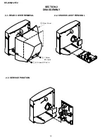
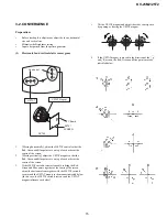
a-d: screen-corner
convergence defect
a
b
c
d
c
a
d
b
Fit the permalloy assembly to the rear
of the CRT to correct the area at fault.
Permalloy
FOCUS
(4)
Screen corner convergence.
•
If you are unable to adjust the corner convergence properly,
this can be corrected by the use of permalloy assemblies.
3-3. Screen [G2], White balance
G2 Setting
1.
Input a dot signal from the pattern generator.
2.
Set the Picture, Brightness and Colour to minimum.
3.
Apply 170Vdc from an external power supply to the
R, G and B cathodes of the CRT.
4.
Whilst watching the picture, adjust the G2 control [RV701
SCREEN] located on the C Board to the point just before the
flyback return lines disappear.
White balance adjustment
1.
Input a ‘PAL’ all-white signal from the pattern generator.
2.
Enter into the Service Mode.
3.
Enter into the ‘Picture’ service menu.
4.
Select the ‘Green drive’ and adjust so that the White Balance
becomes optimum.
5.
Select the ‘Blue drive’ and adjust so that the White Balance
becomes optimum.
6.
Set the Picture to MIN.
7.
Set the ‘R-cut-off’ to 07.
8.
Adjust the ‘G-cut-off’, and the ‘B-cut-off’ so that the White
Balance becomes optimum.
10.
Press the
button to return to TV operation.
3-4. FOCUS
1.
Input a Phillips colour pattern
2.
Set the picture settings to normal.
3.
Adjust the focus control located on the Flyback transformer to
bring the centre of the screen into focus.
Note :Bring only the centre area of the screen into focus, switch to an
all-white pattern and confirm that the magenta ring is hardly
noticed. To obtain optimum focus balance the focus setting
between optimum screen centre focus and a reduced magenta
ring level.
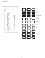
PICTURE
R - Drive
Adj
G - Drive
Adj
B - Drive
Adj
R - cut - off
Adj
G - cut - off
Adj
B - cut - off
Adj
ID - start
02
ID - stop
01
ID - level
01
Bellfo
Adj
Sub Colour
Adj
Sub Brightness
Adj


