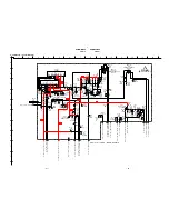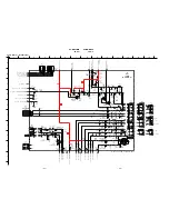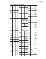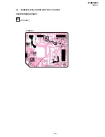
– 28 –
KV-BM14M70
RM-W101
3-3.
PICTURE QUALITY ADJUSTMENTS
PMX/CONTRAST ADJUSTMENT
1. Select Video Mode.
2. Input PAL CB to TV set.
3. Set PICT 03 "PWL" to 00h and WHBL 21 "BLBG" to 01h.
4. Set the following condition:
PICTURE 100%, COLOR 0%, BRIGHTNESS 50%.
5. Connect an oscilloscope to pin
4
(R output) of CN004.
6. Set to Service Mode "PWL" to 00h, “BLBG” to 01h.
7. Select SADJ00 "PMX" with
1
and
4
of the
commander then adjust VR within spec with
3
and
6
.
8. Then press
[MUTING]
t
-
to write the data
9. Set "PWL" and "BLBG" back to initial data repectively.
(PWL: 01h and BLGG: 00h)
SUB COLOR ADJUSTMENT
1. Select Video and set Picture mode.
2. Input PAL 100% CB to TV set.
3. Set PICT 06 "WTS" to 00h.
4. Set the following condition:
PICTURE 100%, COLOR 50%, BRIGHTNESS 50%.
5. Connect an oscilloscope to pin
2
(B output) of CN004.
6. Select to Service Mode and adjust SADJ04 "SCOL"
with
1
and
4
of commander then adjust to
VB2 = VB3 = VB4 with
3
and
6
.
7. Then press
[MUTING]
t
-
to write the data.
8. Set "WTS" back to original data.
SUB HUE ADJUSTMENT
1. Select Video.
2. Input a NTSC 3.58 Color Bar to TV set.
3. Set the following condition:
PICTURE 100%, COLOR 50%, BRIGHTNESS 50%
4. Connect an oscilloscope to pin
2
(B output) of CN004.
5. Set to Service and adjust SADJ01 "SHUE" with
1
and
4
of commander then adjust to VB1 = VB2 =
VB3 = VB4 with
3
and
6
.
6. Then press
[MUTING]
t
-
to write the data.
The highest level of VB1, VB2, VB3, VB4 must be
aligned at the same time.
The ideal difference between VB2 and VB3 is within
±110mV.
For single system with NTSC 4.43 select TV channel
with NTSC 4.43 and repeat 4
t
6.
3-4.
DEFLECTION ADJUSTMENT
H-TRAPEZOID ADJUSTMENT
1. Receive cross hatch/dotsignal.
2. Adjust on to make H-Trapezoid distortion best.
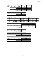
NORMAL MODE (50Hz)
1. Set to Service Mode.
2. Input SPCB Signal (Select Video Mode for USA).
3. Using the
1
and
4
button select GEO (Service
Mode).
4. Rasie/lower data using the
3
and
6
buttons adjust
the following items:-
GEOM :
000
HPOS
Horizontal Shift (HS)
001
HPAR
Horizontal Parallelogram
002
HBOW
Horizontal Bow
003
VLIN
Vertical Linearity
004
VSCR
Vertical Scroll
005
HSIZ
EW Width (EW)
006
EWPW
EW Parabola/Width (PW)
007
UCOP
EW Upper Corner Parabola
008
LCOP
EW Lower Corner Parabola
009
EWTZ
EW Trapezium
010
VSLP
Vertical Slope (VS)
011
VSIZ
Vertical Amplitude
012
SCOR
S-Correction (SC)
013
VPOS
Vertical Shift (VSH)
014
HBL
RGB Blanking Mode
015
WBF
Timing of Wide Blanking (WBF)
016
WBR
Timing of Wide Blanking (WBR)
017
SBL
Service Blanking
018
COPY
Copy the GEO data to all
50/60Hz NVM area
5. Write into memory by pressing
[MUTING]
then
-
on
the remote commander.
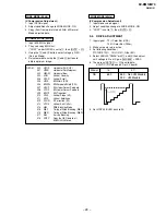
VB2 = VB3 = VB4
(Difference is within 70mV)
VB1
VB2 VB3 VB4
VR
Black
1.46
±
0.03 Vp-p = without VM models
1.65
±
0.03 Vp-p = with VM models
VB1
VB2
VB3 VB4


