– 4 –
KV-HA14M80
RM-969
The units in this man ual contain a self-diagnostic function.
If an error occurs , the STANDBY/TIMER indicator will auto-
matically begin to flash.
The n umber of times the indicator flashes tr
anslates to a probab
le source of the prob
lem. A definition of the
STANDBY/
TIMER flash indicators is listed in the instr
uction man ual f or the user’ s kno wledge and ref erence . If an error symptom
cannot be reproduced, the remote commander can be used to re
view the f ailure occurrence data stored in memor
y to
reveal past prob lems and ho w often these prob
lems occur .
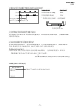
1. DIAGNOSTIC TEST INDICATORS
When an errors occurs
, the STANDBY/TIMER indicator will flash a set n
umber of times to indicate the possib
le cause of
the prob lem. If there is more than one error
, the indicator will identify the first of the prob
lem areas .
Result f or all of the f ollo wing diagnostic items are displa
yed on screen. No error has occured if the screen displa
ys a “0”.
Diagnostic
Item
Descr iption
• Power does not
tur n on
• +B o vercurrent
(OCP)
• Hor izontal
deflection
overdr ive
• White balance
failure (no
PICTURE)
• Ver tical deflection
stopped
• Micro reset
Detected
Symptoms
• Power does not come on.
• No po wer is supplied to
the TV.
• AC po wer supply is f aulty.
• Power does not come on.
• Load on po wer line is
shor ted.
• Has entered standb y state
after hor izontal r aster .
• Power line is shor ted or
po wer supply is stopped.
• Ver tical deflection pulse
is stopped
• Power is shut do wn
shor tly, after this retur n
bac k to nor mal.
• Detect Micro latch up
.
Note 1: If a + B o vercurrent is detected, stoppage of the v
er tical deflection is detected sim
ultaneously .
The symptom that is diagnosed first b
y the microcontroller is displa
yed on the screen.
Note 2: Ref er to screen (G2) Adjustment in section 3-4 of this man
ual.
SELF DIAGNOSTIC FUNCTION
No . of times
STANDBY/TIMER
indicator flashes
Does not light
2 times
4 times
—
Self-diagnostic
displa y/Diagnostic
result
—
002:000 or
002:001~255
004:000 or
004:001~225
101:00 or
101:001~225
Probab le
Cause
Location
• Power cord is not
plugged in.
• Fuse is b ur ned out
F600 (A board)
• H.OUT Q801 is shor ted.
(A board)
• -13V is not supplied.
(A board)
• IC 551 f aulty (A board)
• Discharge CR T
(C Board)
• Static discharge
• Exter nal noise


