background image

– 5 –

KV-HW21P80A

RM-969

5. HANDLING OF SELF-DIAGNOSTIC SCREEN DISPLAY

Since the diagnosis results displayed on the screen are not automatically cleared, always check the self-diagnostic
screen during repairs. When you have completed the repairs, clear the result display to “0”.

Unless the result display is cleared to “0”, the self-diagnosis function will not be able to detect subsequent faults after
completion of the repairs.

[Clearing the result display]

To clear the result display to “0”, press buttons on the remote commander sequentially as shown below when the self-
diagnostic screen is being displayed.

Channel 

[8]

/

0

[Quitting Self-diagnostic screen]

To quit the entire self-diagnostic screen, turn off the power switch on the remote commander or the main unit.

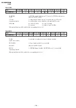
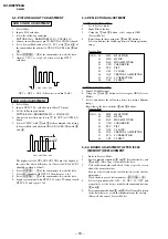
6. SELF-DIAGNOSIS CIRCUIT

[+B overcurrent $OCP%]

Occurs when an overcurrent on the +B(135) line is detected by Q500. If Q500 go to
ON and the voltage to pin 50 of IC301 more than 3.5V when V.SYNC is more than
seven verticals in a period, the unit will automatically turn off.

[Vertical deflection stopped]

Occurs when an absence of the vertical deflection pulse is detected by Pin 17 and
IC001 shut down the power supply.

[White balance failure]

If the RGB levels* do not balance or become low level within 5 seconds, this error
will be detected by IC301. TV will stay on, but there will be no picture.

* (Refers to the RGB levels of the AKB detection Ref pulse that detects IK.)

IC301

Y/CHROMA JUNGLE

IC001

SYSTEM

IC003

MEMORY

MP/
PROTECT

11 DAT1

DAT

11 DAT0

5

50

54

SDA

8

FROM

[+B]

 Q500

17

[V]


D553

53

Summary of Contents for TRINITRON KV-HW21P80A

Page 1: ...REVISION HISTORY BG2T MODEL KV HW21P80A PART NO 9 872 406 01 NO SUFFIX DATE SUPP CORR DESCRIPTION 1 01 2003 10 _ _ 1st Issue CHASSIS ...

Page 2: ...L BG2T MODEL COMMANDER DEST CHASSIS NO KV HW21P80A RM 969 Pakistan TV 1 2 3 4 6 7 8 9 0 5 JUMP SOUND MODE SPACE SOUND PROGR 2 MODEL COMMANDER DEST CHASSIS NO Silver RM 969 Light Blue TV 1 2 3 4 6 7 8 9 0 5 JUMP SOUND MODE SPACE SOUND PROGR 2 ...

Page 3: ...minal Bracket Removal 6 1 6 A Board Removal 6 1 7 Picture Tube Removal 7 2 SET UP ADJUSTMENTS 2 1 Beam Landing 8 2 2 Convergence 9 2 3 Focus Adjustment 11 2 4 G2 SCREEN and White Balance Adjustments 11 3 CIRCUIT ADJUSTMENTS 3 1 Adjustment With Commander 12 3 2 Adjustment Method 12 3 3 Picture Quality Adjustment 18 3 4 Deflection Adjustment 18 3 5 A Board Adjustment After IC003 MEMORY Replacement 1...

Page 4: ...rrent OCP Horizontal deflection overdrive White balance failure no PICTURE Vertical deflection stopped Micro reset Detected Symptoms Power does not turn on No power is supplied to the TV AC power supply is faulty Power does not turn on Load on power line is shorted Has entered standby state after horizontal raster Power line is shorted or power supply is stopped Vertical deflection pulse is stoppe...

Page 5: ...nces of failure for confirmation on the screen To Bring Up Screen Test In standby mode press buttons on the remote commander sequentially in rapid succession as shown below Screen display channel 5 Sound volume Power ON Note that this differs from entering the service mode volume Self Diagnostic screen display Lamp ON 0 3 sec Lamp OFF 3 sec Lamp OFF 0 3 sec 2 times 4 times Diagnosis Item Flash Cou...

Page 6: ...elf diagnostic screen turn off the power switch on the remote commander or the main unit 6 SELF DIAGNOSIS CIRCUIT B overcurrent OCP Occurs when an overcurrent on the B 135 line is detected by Q500 If Q500 go to ON and the voltage to pin 50 of IC301 more than 3 5V when V SYNC is more than seven verticals in a period the unit will automatically turn off Vertical deflection stopped Occurs when an abs...

Page 7: ... Rear cover SECTION 1 DISASSEMBLY 1 2 SPEAKER REMOVAL 1 3 CHASSIS ASSY REMOVAL 1 4 SERVICE POSITION 1 5 TERMINAL BRACKET REMOVAL 1 6 A BOARD REMOVAL 1 1 REAR COVER REMOVAL 1 Two screw BVTP 4 16 1 Terminal bracket 3 Two screw BVTP 4 16 2 One screw BVTP 3 16 ...

Page 8: ...ide of anode cap A metal fitting called the shatter hook terminal is built into the rubber 3 Do not turn the foot of rubber over too hard The shatter hook terminal will stick out or damage the rubber anode button 1 7 PICTURE TUBE REMOVAL Note The picture tube is upside down and the position for the anode cap and tension springs are changed accordingly Please make sure the TV set is not in standing...

Page 9: ...NG 1 Input a white signal with the pattern generator Contrast Brightness 2 Set the pattern generator raster signal to a green raster 3 Move the deflection yoke to the rear and adjust with the purity control so that the green is at the center and the blue and the red take up equally sized areas on each side See Figures 2 1 through 2 4 4 Move the deflection yoke forward and adjust so that the entire...

Page 10: ...gether at the center of the screen adjust the horizontal convergence with the H STAT variable resistor and the V STAT magnet in the manner given below In this case the H STAT variable resistor and the V STAT magnet influence each other so be sure to perform adjustments while tracking 1 3 R G B G R B Center dot C board RV 702 V STAT Magnet H STAT VR BMC Hexapole V STAT Purity V STAT BMC Purity 2 R ...

Page 11: ...H Rotate YCH VOL on DY TLV Rotate TLV VOL ON DY XCV Rotate XCV Adj core on DY ON DY 2 Dynamic Convergence Adjustment Preparation Before starting this adjustment adjust the horizontal static convergence and the vertical static convergence RB TLV YCH B R YCH TLV a d c b a to d Permalloy assembly Fix a Permalloy assy corresponding to the misconverged areas ...

Page 12: ... 175 V 2 VDC 2 a WHITE BALANCE ADJUSTMENT 1 Set to Service Mode Refer Section 3 1 ADJUSTMENTS WITH COMMANDER 2 Input white raster signal 3 Set 49 ABL and IF VP2 service mode to 00 4 Set Picture to DYNAMIC 5 Select OB RDR with 1 and 4 and set the level to 25 with 3 and 6 for best white balance 6 Select OC GDR and OD BDR with 1 and 4 and adjust the level with 3 and 6 for the best white balance 7 Wri...

Page 13: ...The standard is 1F for PAL reception 4 Write with the MUTING button The display changes to WRITE 5 Execute the writing with the 0 button The WRITE display will be changed to red color while excuting and back to SERVICE Example on screen display e OTHER FUNCTION VIA REMOTE COMMANDER 7 0 All the data becomes the values in memory 8 0 All user control goes to the standard state 5 0 Service data initia...

Page 14: ... 0 2 0 2 0 1 I M P 4 0 4 0 F 3 a t a D m u m i n i M e r u t c i P 4 0 1 1 U H S 7 0 5 0 F 0 e u H b u S o e d i V V T 7 0 9 0 2 1 H S S 1 0 3 0 1 0 3 0 s s e n p r a h S b u S o e d i V V T 3 1 1 C S 0 2 F 1 F 3 r e w o L r o l o C b u S z H 0 6 0 5 0 2 C 1 4 1 2 C S 8 0 F 3 r e h g i H r o l o C b u S z H 0 6 0 5 5 1 O F 0 0 0 0 3 0 t n a t s n o C e m i T 1 0 t x e t e l e T o e d i V V T 0 0 0...

Page 15: ...F F n o i t i s o P y a l p s i D l a t n o z i r o H 8 5 4 6 2 5 A A S A 2 9 3 V X T 7 2 7 2 F 3 c n y s V m o r f t e s f f o e n i l n o i t i s o P y a l p s i D l a c i t r e V 7 2 A 3 D H T 0 0 0 0 F 7 t f i h S e g d E e v i t c A c n y s H 0 0 B 3 D V T F 3 F 3 F 7 t f i h S e g d E e v i t c A c n y s V F 3 C 3 L P H 1 0 1 0 1 0 n o i t a r u g i f n o C y t i r a l o P c n y s H e v i t ...

Page 16: ...1 PAL matrix 0 adapted to standard 0E 7 DS Dynamic skin control on off 1 on 0 off 1A 3 DSA Dynamic skin control angle 1 correction angle 117 degrees 0 correction angle 123 degrees 1A 2 EBS Extended Blue Stretch 1 on 0 off 1A 0 BLS Blue stretch 1 on 0 off 18 4 BKS Black stretch 1 on 0 off 18 3 BB Blue back when no video signal is identified 1 on 0 off 18 0 AKB Black current stabilisation 1 not acti...

Page 17: ...ion will be enabled if the corresponding bit is set to 1 No 50 OP3 No Bal 1 no balance in analog select items 0 balance included for AV stereo model SPC SOUND 1 Space Sound available 0 not available Korean ST Reserved for NTSC model H K Bil 1 NICAM bilingual available No NICAM stereo 0 not available for monaural model Other optional function will be enable if the corresponding bit is set to 1 No 4...

Page 18: ...o NVM push the commander button mute and 0 sequentially Read data from NVM push the commander button 7 and 0 sequentially Copy 50Hz data into 60Hz area push the commander button display and 0 sequentially SELF DIAGNOSIS MODE How to enter Self Diagnosis Mode At stand by push the commander button display 5 vol and power sequentially How to exit Self Diagnosis Mode Push the commander button other ON ...

Page 19: ...B3 VB4 3 4 DEFLECTION ADJUSTMENT NORMAL MODE 50Hz 1 Set to Service mode 2 Input PAL color bar 3 Using the 1 and 4 button select category GEO Service Mode 4 Raise lower the data using the 3 and 6 buttons Select and adjust the following items to obtain optimum image Service Item GEO 00 HPS H POSITION 01 HSZ H SIZE 02 PAP PIN AMPLITUDE 03 CPN CORNER PIN 04 TLT TILT 05 VSL V SLOPE 06 VAP VERTICAL AMPL...

Page 20: ...RM 969 3 6 PICTURE DISTORTION ADJUSTMENT Item Number 00 08 01 HSZ H SIZE 04 TLT TILT 06 VAP VERTICAL AMPLITUDE 00 HPS H POSITION 02 PAP PIN AMPLITUDE 03 CPN CORNER PIN 05 VSL V SLOPE 08 VPS V SHIFT 07 SCO S CORRECTION ...

Page 21: ...LK SCL 7 8 SDA 30 29 38 31 32 22 50 R Y OUT B Y OUT CVBS OUT B Y R Y ABL EHTX RAY IC301 Y C JUNGLE X443 4 43MHz X358 3 58MHz IF OUT CVBS IN INT 6 13 H PROT Q004 Q800 H DRIVE 3 1 PIN CONT IC850 IC851 Q802 PIN OUT IC551 V OUT 5 1 7 Q801 H OUT L802 DUMPER D804 D851 S801 H SENT FV HV 135V 13V 15V T503 FBT Q561 X RAY 135V D561 D591 D1505 H H H H V V DY1 2 1 4 200V 1000V H1 CN851 RGB RGB Amp 1000V 200V ...

Page 22: ...signal input Readings are taken with a 10 MΩ digital multimeter Voltage are dc with respect to ground unless otherwise noted Voltage variations may be noted due to normal production tolerances All voltage are in Volt Cannot be measured Circled numbers are waveform references B bus B bus signal path Reference information RESISTOR RN METAL FILM RC SOLID FPRD NONFLAMMABLE CARBON FUSE NONFLAMMABLE FUS...

Page 23: ... 2W 33k 3W RS 470p 500V B 470p 250V B 100 16V FLR50 1k CHIP GP 08D 1 5k FPRD 1S S 119 25TD1S S355T E 17 0 001 50V B CHIP 180k RN 56k CHIP 2SA1091 0 56k CHIP 100 16V 0 CHIP NJM2903 180k RN CP 0 CHIP 10k CHIP 2S C5885 HDT 1k 3W RS 1k 3W RS 5 6k CHIP 100k CHIP 0 01 F CHIP 1k CHIP 10k CHIP 33k CHIP 150K CHIP 220k RN 100k RN CP 100 2W RS 1 250V 4 7mmH GP08D H CENT 1 JW 5MM 2 2K 10m H 330p 2kV B 220k 1 ...

Page 24: ... 0 CHIP R778 R775 R777 R765 100 1 2W D755 HSS82 TJ R764 100 1 2W C787 1000P 500V L783 5MM L782 5MM L781 5MM R756 1K 1 2W R757 1K 1 2W R763 100 1 2W D756 HSS82 TJ R794 0 47 D754 HSS82 TJ L750 C759 R784 56P CHIP R785 56P CHIP R786 56P CHIP C790 R752 220 R753 220 C789 R768 R767 R766 C788 R754 220 Q701 D782 UDZSTE 175 6B C783 0 001 B R776 CN701 6P R783 100 1 2W C782 0 001 B D780 1SS133T 77 D781 1SS133...

Page 25: ...6 4 9 57 4 7 58 0 2 59 0 01 60 8 9 61 0 17 62 0 63 0 64 4 9 IC002 I 0 2 4 9 3 4 8 4 12 2 5 4 9 6 0 7 0 IC003 1 0 2 0 3 0 4 0 5 4 9 6 4 9 7 0 8 4 9 IC004 VCC 4 8 G 0 O 4 22 IC201 1 4 5 2 4 5 3 4 5 4 4 5 5 4 5 6 4 5 7 4 5 8 4 5 9 4 5 10 4 5 11 4 5 12 4 5 13 4 5 14 4 5 15 4 5 16 4 5 17 4 5 18 4 5 19 4 5 20 0 21 4 7 22 4 7 23 4 5 24 9 25 0 26 3 8 27 3 8 28 4 5 IC203 1 0 2 0 3 20 5 4 0 5 0 6 0 7 10 1 8...

Page 26: ...6 2 9 7 3 7 8 8 9 PH600 1 134 2 133 3 3 4 16 Q001 B 0 C 4 9 E 0 Q002 B 0 C 4 9 E 0 Q003 B 0 C 4 9 E 0 1 Q004 B 0 1 C 4 9 E 0 Q005 B 0 1 C 4 7 E 0 Q100 B 4 2 C 8 9 B 3 6 Q101 B 0 01 C 8 99 E 0 Q102 B 3 1 C 2 4 E 5 1 Q103 B 0 C 0 E 0 Q104 B 0 C 0 E 0 Q105 B 0 3 C 0 E 0 Q106 B 0 C 3 9 E 0 Q201 B 6 2 C 8 9 E 5 6 Q202 B 14 1 C 1 3 E 12 2 Q203 B 5 5 C 14 E 4 8 Q204 B 20 9 C 21 6 E 21 7 Q205 B 4 7 C 0 E ...

Page 27: ...5 5 3 6 199 7 151 8 151 9 150 J751 3 327 4 0 5 0 6 0 24 80V 4 7 0 8 140 140 0V 3 C BOARD VOLTAGE LIST AND WAVEFORM Ref Pin No Voltage v A BOARD VOLTAGE LIST AND WAVEFORM Ref Pin No Voltage v Q801 B 94 2 C 137 6 19 40V 14 E 0 Q802 S 0 G 5 8 656 0mV 15 O 9 9 Q850 B 5 9 C 8 9 E 5 6 Q851 B 5 9 C 0 E 0 DY1 1 600V 12 Ref Pin No Voltage v Ref Pin No Voltage v 9 153 118 0V 2 10 153 126 0V 1 11 0 Q701 B 5 ...

Page 28: ...6 D320 E 6 D321 D 6 D322 C 4 D323 B 4 D324 C 3 D325 D 4 D326 D 7 D327 A 7 D328 E 6 D329 C 3 D330 C 3 TRANSISTOR D331 D 5 D332 C 5 D333 C 5 D400 D 10 D401 E 10 D405 B 1 D406 C 1 D407 A 2 D410 E 10 D500 H 6 D501 H 5 D502 J 4 D503 J 3 D504 I 4 D522 J 5 D553 I 6 D600 I 8 D601 H 11 D602 I 9 D603 I 8 D604 I 8 D605 I 8 D606 I 8 D607 G 8 D608 G 7 D609 F 9 D625 J 8 D800 F 1 D802 F 4 D803 F 4 D804 G 2 D805 ...

Page 29: ... 31 KV HW21P80A RM 969 RGB AMPLIFER C C Board PRINTED WIRING BOARDS ...

Page 30: ...162 G E B C 2SC3209LK E C B IC IRF614 005 2SC3779C D AA S D G E B C CXP85224A 080S M24C08 BN6 A 8 PIN TDA8843 N2 1 TOP VIEW DIP Dual In line Package Pin 6 98 MA8024 UDZSTE 1727B UDZSTE 175 6B ANODE CATHODE STR F6707A SE135N D1NL20U EL1Z EGP20G GP08D 2SK208 GR TE85L MC4558CD MM1319AFBE NJM2903M Small Outline L Leaded Pin 8 98 1 TOP VIEW SOP PQO9RD11 1234 CATHODE ANODE CATHODE ANODE CATHODE ANODE CA...

Page 31: ... 33 KV HW21P80A RM 969 AN5522 1 2 4 6 3 5 7 TDA6107Q N2 AN5276 RPM7140 H5 IC 1 9 ...

Page 32: ... CORD 22 4 095 890 51 BRACKET TERMINAL ICON 23 1 823 478 12 CORD AC POWER WITH CONNECTOR 24 4 092 370 01 BRACKET FBT 25 4 036 405 11 SPRING COMPRESSION 26 4 046 981 03 BRACKET SPEAKER 27 4 095 941 01 SCREW WH DIA 16 P 4X16 28 4 092 367 01 GUIDE LIGHT 29 4 093 771 01 COVER FRONT PANEL SECTION 5 EXPLODED VIEWS Items marked are not stocked since they are seldom required for routine service Some delay...

Page 33: ...1 163 038 00 CERAMIC CHIP 0 1UF 25V C050 1 163 009 11 CERAMIC CHIP 0 001UF 10 00 50V C051 1 163 038 00 CERAMIC CHIP 0 1UF 25V C052 1 126 935 11 ELECT 470UF 20 00 10V C053 1 126 935 11 ELECT 470UF 20 00 10V C054 1 104 666 11 ELECT 220UF 20 00 25V C055 1 163 001 51 CERAMIC CHIP 220PF 10 50V C056 1 163 251 11 CERAMIC CHIP 100PF 5 00 50V C057 1 163 001 51 CERAMIC CHIP 220PF 10 50V C058 1 163 001 51 CE...

Page 34: ...1 CERAMIC CHIP 0 0022UF 10 00 50V C353 1 107 823 51 CERAMIC CHIP 470000PF 10 16V C354 1 163 017 00 CERAMIC CHIP 0 0047UF 10 00 50V C355 1 107 823 51 CERAMIC CHIP 470000PF 10 16V C356 1 164 232 11 CERAMIC CHIP 0 01UF 10 00 50V C357 1 163 009 11 CERAMIC CHIP 0 001UF 10 00 50V C358 1 163 251 11 CERAMIC CHIP 100PF 5 00 50V C359 1 163 038 00 CERAMIC CHIP 0 1UF 25V C360 1 136 165 00 FILM 0 1UF 5 00 50V ...

Page 35: ...00 1 564 508 11 PLUG CONNECTOR 5P CN600 1 508 786 00 PIN CONNECTOR 5MM PITCH 2P CN601 1 691 134 11 PIN CONNECTOR PC BOARD 2P CN602 1 580 843 11 PIN CONNECTOR POWER TRIMMER CT131 1 767 774 22 TRAP CERAMIC CT139 1 767 775 22 TRAP CERAMIC CT355 1 795 343 21 TRAP CERAMIC T55B DIODE D001 8 719 083 18 DIODE SPB 25MVWF D004 8 719 911 19 1SS119 25 D005 8 719 069 55 DIODE UDZSTE 175 6B D006 8 719 123 54 RD...

Page 36: ...184 41 INDUCTOR 15UH L100 1 414 856 11 INDUCTOR 10UH L101 1 410 498 11 INDUCTOR 1 2UH L102 1 410 985 42 INDUCTOR 0 22UH L103 1 410 987 42 INDUCTOR 0 33UH L200 1 249 401 11 CARBON 47 5 1 4W L300 1 410 511 11 INDUCTOR 15UH L305 1 410 510 11 INDUCTOR 12UH L308 1 410 501 11 INDUCTOR 2 2UH L400 1 414 187 11 INDUCTOR 47UH L500 1 408 947 00 INDUCTOR 2 2MH L600 1 412 533 21 INDUCTOR 47UH L601 1 414 487 41...

Page 37: ... METAL CHIP 33 5 1 10W R106 1 216 065 61 RES CHIP 4 7K 5 1 10W R107 1 216 063 61 RES CHIP 3 9K 5 1 10W R108 1 216 041 61 RES CHIP 470 5 1 10W R109 1 216 019 61 METAL CHIP 56 5 1 10W R115 1 216 065 61 RES CHIP 4 7K 5 1 10W R117 1 216 081 61 RES CHIP 22K 5 1 10W R118 1 216 041 61 RES CHIP 470 5 1 10W R119 1 216 081 61 RES CHIP 22K 5 1 10W R120 1 216 055 61 RES CHIP 1 8K 5 1 10W R121 1 216 081 61 RES...

Page 38: ... 216 073 61 RES CHIP 10K 5 1 10W R866 1 216 049 61 RES CHIP 1K 5 1 10W R867 1 208 812 11 METAL CHIP 18K 0 5 1 10W R868 1 249 393 11 CARBON 10 5 1 4W R869 1 249 381 11 CARBON 1 5 1 4W R870 1 218 760 11 METAL CHIP 220K 0 5 1 10W R329 1 216 043 61 RES CHIP 560 5 1 10W R330 1 216 295 61 SHORT CHIP 0 R331 1 216 295 61 SHORT CHIP 0 R332 1 216 295 61 SHORT CHIP 0 R333 1 216 041 61 RES CHIP 470 5 1 10W R3...

Page 39: ...PACITOR C751 1 107 652 11 ELECT 10UF 20 00 250V C752 1 115 350 51 CERAMIC 0 0047UF 2KV C753 1 162 318 11 CERAMIC 0 001UF 10 00 500V C754 1 107 651 11 ELECT 4 7UF 20 00 250V C781 1 107 651 11 ELECT 4 7UF 20 00 250V C782 1 102 074 00 CERAMIC 0 001UF 10 00 50V C783 1 163 009 11 CERAMIC CHIP 0 001UF 10 00 50V C786 1 163 009 11 CERAMIC CHIP 0 001UF 10 00 50V C787 1 164 645 11 CERAMIC 1000PF 10 00 500V ...

Page 40: ...S 1 501 730 41 ANTENNA TELESCOPIC 1 417 151 22 MATCHING TRANSFORMER ANTENNA 1 417 151 31 MATCHING TRANSFORMER ANTENNA 1 417 151 41 MATCHING TRANSFORMER ANTENNA 3 701 910 00 SCREW SPECIAL DIA 3 8X20 4 039 372 01 BAG PROTECTION 4 091 756 02 CUSHION LOWER 4 091 757 02 CUSHION UPPER 4 096 831 02 INDIVIDUAL CARTON C English 2003 10 Sony Corporation Sony Technology Malaysia Sdn Bhd Visual Products 4 392...

Page 41: ...GB _4 098 715 11 1 Group P19 Trinitron Color TV Operating Instructions Before operating the unit please read this manual thoroughly and retain it for future reference KV HW21 2003 Sony Corporation 4 098 715 11 1 P80A GB ...

Page 42: ...esetting press SELECT b PROG SELECT b SELECT Press SELECT on the remote until LANGUAGE ENGLISH appears on the screen then press or to change the on screen display language Connect the antenna cable not supplied to 8 antenna input at the rear of the TV Tip You can also connect your TV to other optional components See E Step 1 Insert the batteries supplied into the remote Note Do not use old batteri...

Page 43: ... high voltages and other hazards are present inside the TV Refer servicing and disposal of the TV to qualified personnel Your TV is recommended for home use only Do not use the TV in any vehicle or where it may be subject to excessive dust heat moisture or vibrations Do not block the ventilation openings of the TV Do not install the TV in a confined space such as a bookcase or built in cabinet For...

Page 44: ...ew one clamp to a wall or pillar and the other clamp to the provided hole at the rear of your TV Note Use only the supplied screws Use of other screws may damage the TV 20 mm 3 8 mm screws clamps band or Do not plug in too many appliances to the same power socket Do not damage the power cord Pull the power cord out by the plug Do not pull the power cord itself Even if your TV is turned off it is s...

Page 45: ...tton Function 1 Turn off or turn on the TV 2 Remote control sensor 3 Wake Up indicator 3 1 Standby indicator 5 PROG Select program number 6 2 Adjust volume 7 t Select TV or video input 8 SELECT Select the desired item 4 9 t Video input terminal 0 8 Antenna input terminal You can also use the 2 buttons on the TV to work as the buttons on the remote TV top control panel ...

Page 46: ...nel Camcorder Audio Video cable not supplied Note Do not connect video equipment to t video input at the front and the rear of your TV at the same time otherwise the picture will not be displayed properly on the screen TV rear panel Audio Video cable not supplied L R MONO L R MONO VCR Video game equipment Antenna cable not supplied ...

Page 47: ...e TV Press 2 to increase the volume level Press to cancel the muting Do not use a hair dryer or other equipment near the TV Check the antenna setup Contact a Sony dealer for advice Use the fine tuning FINE function See J Turn off or disconnect the booster if it is in use Check the antenna setup Contact a Sony dealer for advice Select the appropriate color system See J Adjust the color level See K ...

Page 48: ... S01 to S03 S1 to S41 8 Antenna 75 ohm external terminal Audio output Speaker 5W 5W Number of terminal Video Input 2 Phono jacks 1 Vp p 75 ohms One input line available Audio Input 2 Phono jacks 500 mVrms One input line available Picture tube 21 in Tube size cm 54 Measured diagonally Screen size cm 51 Measured diagonally Dimensions w h d mm 630 460 492 Mass kg 25 G Specifications Design and specif...

Page 49: ...ms 0 Display on screen information qa Mute the sound qd t Select TV or video input qf 0 9 Input numbers Timer operations qj Set TV to turn on automatically qk Set TV to turn off automatically qg SOUND MODE Select sound mode ql SPACE SOUND Select space sound mode qh A B Not function for your TV Teletext operations green label 8 x red green yellow blue 0 qs Not function for your TV qd qh qj qk See K...

Page 50: ...andby mode Setting the Sleep timer Press until the desired period of time appears on the screen The Sleep timer starts immediately after you have set it Notes You can also cancel the Wake Up and Sleep timers by turning off the TV s main power If no buttons or controls are pressed for more than two hours after the TV is turned on using the Wake Up timer the TV automatically goes into standby mode 1...

Page 51: ...een 2 Press or once to enter the AUTO PROGRAM mode The on screen display will start flashing 3 Press PROGR or the number buttons until the desired program number appears on the screen 4 Press or to start presetting channels automatically Presetting channels manually 1 Press SELECT until MANUAL PROGRAM appears on the screen 2 Press or once to enter the MANUAL PROGRAM mode 3 Press PROGR or the numbe...

Page 52: ...to enter the MANUAL PROGRAM mode 4 Press PIC MODE to skip the unused or unwanted program number 5 Press SELECT to exit the MANUAL PROGRAM mode Note To restore the skipped program number again preset the channel automatically or manually To use the fine tuning function The fine tuning FINE function may help to reduce the following problems double images and lines moving across the TV screen You can...

Page 53: ... the desired sound mode Select To 9 DYNAMIC listen to dynamic and clear sound that emphasizes the low and high sound 9 DRAMA listen to sound that emphasizes vocals and background music 9 SOFT listen to soft sound Adjusting the picture and sound settings 1 Press SELECT until the desired setting appears Each time you press SELECT the setting item will change as follows 2 Press or to adjust the item ...

Page 54: ...ng the space sound mode Press SPACE SOUND Select To ON listen to monaural sound with a stereo like effect OFF turn off space sound mode Note You can also turn space sound on or off using the SELECT and or buttons Customizing the picture and sound continued ...

Reviews: