


–
20
–
KV
-XG29M90
RM-952
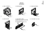
SECTION 2
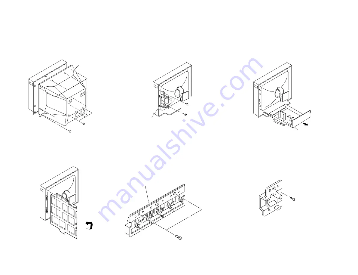
DISASSEMBLY
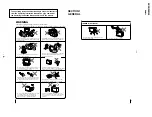
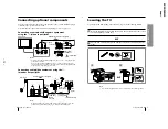
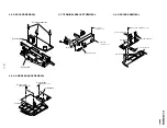
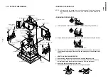
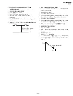
2-4. SERVICE POSITION
2-3. CHASSIS ASSY REMOVAL
2-2. SPEAKER REMOVAL
2-1. REAR COVER REMOVAL
2
Eight screws
(+BVTP 4
×
16)
3
Three screws
(+BVTP 4
×
16)
1
Rear cover
1
Eight screws
(+BVTP 4
×
16)
3
Four screws
(+BVTP 3
×
16)
2
Bracket, speaker
1
Chassis assy
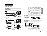
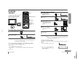
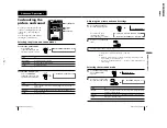
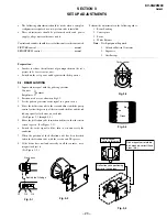
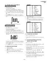
2-5-2. REPLACEMENT OF LIGHT GUIDE
2-5. REPLACEMENT OF PARTS
For replacement of the Control Button and Light Guide,
unscrew them, exchange with the new parts, and fix them
with screws (+BVTP) respectively.
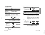
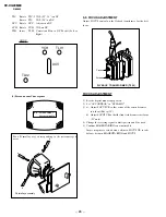
2-5-1. REPLACEMENT OF CONTROL BUTTON
Control button
Two screws
(+BVTP 3
×
12)
One screw
(+BVTP 3
×
12)
Summary of Contents for Trinitron KV-XG29M90
Page 1: ......


