background image

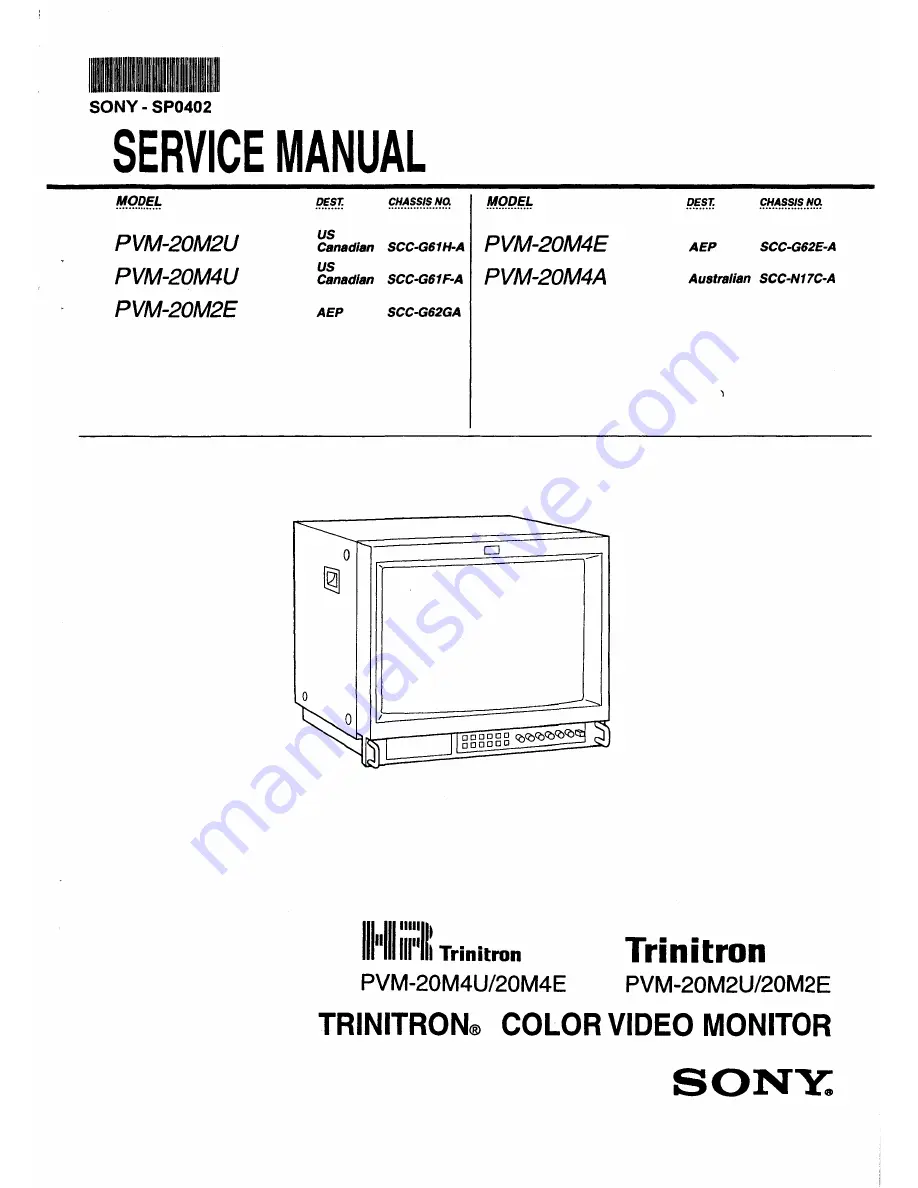
Summary of Contents for Trinitron PVM-20M2E

Page 1: ... 20M4U PVM 20M2E 1 M QP g us PVM 20M4E Canadian SCC G61H A us PVM 20M4A Canadian SCC G61F A AEP SCC G62GA 0 0 J lllnllllll m Trinitron PVM 20M4U 20M4E AEP SCC G62E A Australian SCC N17C A Trinitron PVM 20M2U 20M2E TRINITRON COLOR VIDEO MONITOR SONY ...

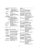
Page 2: ... area 0 5 mm typical Peripheral area 0 7 mm typical Raster size stability H 1 0 V 1 5 High voltage regulation 4 0 Color temperature 065 D93 selectable USER 3 200K 10 000K factory setting is 065 For PVM 20M2U 20M2E Normal scan Under scan H linearity V linearity Convergence 7 over scan of CRT effective screen area 5 underscan of CRT effective screen area Less than 5 0 typical Less than 5 0 typical C...

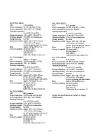
Page 3: ...consumption 90 Wh with SDI 99 Wh Power requirements 120 V AC 50 60Hz Operating temperature 0 to 35 C 32 to 95 F Storage temperature 10 to 40 C 14 to104 F Operating humidity 35 to 85 no condensation Storage humidity 0 to 90 Dimensions w h d Approx 346 x 340 x 431 mm 13 x 13Y2 x 17 inches not incl projecting parts and controls Mass Approx 16 7kg 36lb 13 oz Accessory supplied AC power cord 1 AC plug ...

Page 4: ...40 C 14 to104 F Operating humidity 35 to 85 no condensation Storage humidity 0 to 90 Dimensions w h d Approx 450 x 458 x 503 mm 17 x 18Ys x 197 As inches not incl projecting parts and controls Mass Approx 30 0 kg 66 lb 2 oz Accessory supplied AC power cord 1 AC plug holder 1 Tally label 1 Cable with a 20 pin connector 1 4 For PVM 20M2U CRT P 22 phosphor Power consumption 115 Wh with SDI 125 Wh Pow...

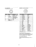
Page 5: ...or 20 pin 4 EXT SYNC Yellow 5 DEGAUSS Green 6 R chON OFF Blue 7 TALLY Purple 10 11 GND 12 GND Spiral Grey Spiral Pink 20 16 9 Spiral Light Blue For digital audio control How to connect a remote control unit Connect No 17 pin to one of the GND pins No 9 12 and 15 then connect pins for the functions you want to use to other GND pins No 9 12 and 15 How to light the tally lamp Connect No 7 pin to one ...

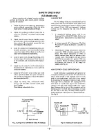
Page 6: ...eakage LEAKAGE TEST The AC leakage from any exposed metal part to earth ground and from all exposed metal parts to any exposed metal part having a return to chassis must not exceed 0 5mA 500 microampers Leakage current can be measured by any one of three methods l A commercial leakage tester such as the Simpson 229 or RCA WT 540A Follow the manufactures instructions to use these instru ments 2 A b...

Page 7: ...HIS MANUAL FOLLOW THESE PROCEDURES WHENEVER CRITICAL COMPONENTS ARE REPLACED OR IMPROPER OPERATION IS SUSPECTED Section Title 5 CIRCUIT ADJUSTMENTS 5 l A Board Adjustments 27 6 DIAGRAMS 6 1 Block Diagrams 1 39 Block Diagrams 2 44 6 2 Frame Schematic Diagram 49 6 3 Circuit Boards Location 52 6 4 Printed Wiring Boards and Schematic Diagrams 52 A Board 113 59 A Board 213 66 A Board 3 3 69 Q Board 74 ...

Page 8: ...ector with A Ir mark only The input conneclor is terminaced at 75 ohms inside when no cable is connected 10 rhe loop through output connector When a cable is connected to an output connector the 75 ohm termination is automatically released 2 The NTSCuJ system refers 10 an NTSC color system in which rhe subcarrier freQuency is modified to 4 43MHz When D t l 1 t 1 t l l l 0ID 1 ayen lack with aTride...

Page 9: ...his selector light on for underscanning The display size is reduced by approximately 5 so that four comers of the raster are visible 4D BLUE ONLY selector RESET button As the BLUE ONLY selector press this selector light on to eliminate the red and green signals Only blue signal is displayed as an apparent monochrome picture on the screen This facilitates chroma and phase adjustments and observatio...

Page 10: ...audio input of a VCR or another monitor 0 REMOTE connector 20 pin Connect to the tally output of a control console special effect generator etc The tally lamp on the front panel will be turned on and off by the connected equipment This connector can also be used for connecting a remote control unit For details on the pin assignment of this connector see page 19 8 RGB COMPONENT connectors RGB signa...

Page 11: ...table shows how these five buttons function when using the menus MENU 0 ENTER f l iD il 0 return to the previous menu return to the previous menu decide a selected item select an adjustment item move the cursor upwards increase selected value move the cursor downwards decrease selected value reset current settings to the factory setting The buttons that can he used on the menus and adjustment scre...

Page 12: ... the caption type in this menu OFF USER CONFIG 1 menu Select an item to adjust on the menus and screens 1J11 through To go to the USER CONFIG 2 menu select NEXT PAGE USER CONFIG 2 menu Select an item to adjust on the menus and screens through To go to the USER CONFIG I menu select PREVIOUS PAGE l AUTO ADJUST screen Select the color bar signal full SMPTE EIA and press ENTER SELECT to start automati...

Page 13: ... the or tl button until the lines are displayed on the screen as horizontally as possible When the signals of the white color are input and displayed Press the or tl button until the white color on the screen become as uniform as possible To reset the setting to standard 00 press the RESET button 14 Connections v tJ tew t t 61irJ 2f 11 _br JJ 2Yi ltJ fgi 5 J Connect the AC power cord supplied to t...

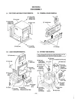
Page 14: ...cover 1 Three screws CASE CLAW SCREW OS Seven nylon rivet Four screws BVTP 4X16 2 3 J AND H BOARDS REMOVAL cabinet assy D Two claws 2 4 PICTURE TUBE REMOVAL When exchange the Picture tube of PVM 20M4 series and if thE magnet had stuck on the neck of the Picture tube peel it One screw EXT TOOTH WASHER SCREW M One screw EXTTOOrH WASHER 14 ...

Page 15: ...in the direction indicated by the arrow When one side of the rubber cap is separated from the anode button the anode cap can be removed by turning up the rubber cap and pulling up it in the direction of the arrow HOW TO HANDLE AN ANODE CAP CD Don t hurt the surface of anode caps with sharp shaped material Don t press the rubber hardly not to hurt insilie of anode caps A material fitting called as ...

Page 16: ...rned with the MENU key and forwarded with the ENTER key When a key is continuously pressed the op eration will be repeated 7 Change of service data The service data is made larger with the t key and smaller with the key When continuously pressing the keys the operation will be repeated 8 Reading of service data When reading data from the ROM to the RAM press the B I 0 key once and check than the R...

Page 17: ...0 PAL PHASE NORMAL 255 110 110 51 PHASE ACC OFF 255 105 111 S B Y PHASE 255 122 112 53 CHROMA NORMAL 255 109 113 54 CHROMA ACC OFF 255 41 114 55 R YLEVEL 255 121 115 56 SECAM CHROMA 255 m 116 Sl R YLEVEL 255 181 117 58 COLOR BALANCE R Y 255 118 118 00 COLOR BALA CE B Y 225 135 119 6 C T1 D 3200KSW 1 0 120 17 Signify The setting is vary with the destination Refer to the Table 3 1 Table map 2 MAX ST...

Page 18: ... 93 65 PVM 20M4E 2 0 3 65 93 PVM 20M2E 2 0 4 65 93 PVM 14M4U 1 1 5 65 93 PVM 14M2U 1 1 6 65 93 PVM 14M4J 2 0 7 93 65 PVM 14M1J 2 0 8 93 65 PVM 14M4E 2 0 9 65 93 PVM 14M2E 2 0 10 65 93 PVM 20M4A 2 0 11 65 93 PVM 14M4A 2 0 12 65 93 PVM 14M2A 2 0 13 65 93 PVM 14M4B 1 1 14 65 93 BVM 14M4DJ 2 0 15 93 65 BVM 14M4DE 2 0 16 65 93 PVM 20M4T 2 0 17 93 65 PVM 14M4T 1 0 18 93 65 18 ...

Page 19: ...wer after adjustment in the service mode write the adjustment data When the power is turned off before writing adjusted data will all be lost 3 3 Writing model data I Write model data on respective models in the service mode at the location of No ll4 MODEL in accordance with Table 3 4 Table 3 4 Model Model data PVM 20M4U 0 PVM 20M2U 1 PVM 20M4J 2 PVM 20M4E 3 PVM 20M2E 4 PVM 14M4U 5 PVM 14M2U 6 PVM...

Page 20: ...nter of the screen Make R and B almost identical Fig 3 1 5 Switch to Bonly R only and G only and verify each Figs 3 l 3 2 and 3 3 6 Bring the deflection yoke gradually forward and adjust the de flection yoke so that R and B on both sides of the screen will be green Fig 3 2 Fig 3 3 7 If the deflection yoke comes forward too much the pattern shown in Fig 3 4 will appear If so move the deflection yok...

Page 21: ...ti cal convergence X y Fig 3 14 Good example If the A and B knobs are not symmetrical I 1 the focus may deteriorate beam striking or other adverse effects may occur y Fig 3 15 Bad example 4 For HMC use the BMC Mg to adjust the R and B dots so that they will be symmetrical horizontally with respect to the G dot 6 pole magnet Change the opening degree of the BMC Mg to control the HMC R G B r Control...

Page 22: ...the CRT viewed from the CRT screen screen H H H H R B B R B R R B Fig 3 20 Fig 3 21 3 Insert the wedge between the deflection yoke and CRT funnel to lock the deflection yoke Fig 3 24 Groups of models Group of models 4 have 1 2 3 and 5 have been been treated treated Fig 3 24 4 The following patterns cannot be corrected by turning the neck Figs 3 25 3 26 and 3 27 RGB Gun rotatuon R G g B f 0 B o G o...

Page 23: ...eft end of the wavefonn will be 1 35 V 0 05 V 1 35V V synchronization GND The waveform is a rectangle as shown on the left ____ Adjust the left corner so that it will be 1 35V Fig 3 29 3 10 White balance adjustment 1 Input a 525 monoscope signal Input from LINE A or B with no burst 2 Set as follows CONT O BRT 50 3 Adjust SUB BRIGHT in the service mode so that the 20 tone gray scale will be as foll...

Page 24: ...at time both ends of the central section of the screen are in the same state Dot 7 8 Correct focus Connected dot Fig 3 30 6 Check that the resolution is more than 800 lines by means of a digital monoscope signal 7 Check that the magenta ring is unconspicuous by means of an all white signal Fig 3 31 Movement of VR when viewed from the front 2 PVM 14M4 Series l Adjust the H focus upper side of focus...

Page 25: ...NFIRAMATION OF HOLD DOWN CIRCUIT Check Condition Input voltage 130 VAC Input signal White Dot Controls BRT Cont Max Min 4 2 1 Hold Down Circuit B a Adjust the beam current to 600 50J IA with the pin ofCN605 with the external DC power supply less than 127 0 VDC to the point just before the hold down circuit works Input Signal White b Adjust the beam current to 80 20J IA with the pin of CN605 with t...

Page 26: ... A BOARD Compone t Side II ol TP503 digital multimeter EJ i 26 ...

Page 27: ...64V BETAO 75 1owhite 0 525 0 498V 75 color B Y A Y Compo P P lor this 0 7V 0 664V nent item only 75 color 100 1owhite 0 7V 0 664V bar 75 1owhite 0 525V 0 498V SMPTE 75 color B Y A Y 0 525 0 498V P P lor this item only OTPJOO 1 CN401 8 J TP402 0 zz IC507 rz C 6 J C 1 l IC50J e r I 8 IC502 16 L J I 8 2 Preparation RV501 In this chapter D indicates the control items in the service mode Example 160 H ...

Page 28: ...prox 1 em to the inside of the effective screen 6 Tum RV50l H CENT so that B B 7 Adjust 160 VIDEO PHASEI so that the signal area will be in the cen ter A A of the deflection area Fig 5 4 8 Input a 625 monoscope signal 9 Adjust lsoVIDEOPHASEI in the same manner Deflection area Signal area Effective screen Fig 5 4 4 V BLANKING adjustment l Input a 525 monoscope signal 2 Set the unit in the UNDER SCA...

Page 29: ...st INORSOV SIZBI so that the SIZE will equal the standard value 10 Set the unit in the 16 9 mode 11 Adjust 116 9 NOR V SIZB SO I so that it will equal the standard value Table 5 3 NORMAL V SIZE standard 525 625 4 3 11 75 0 2 frames 11 2 0 2 frames 14 154mm 16 9 20 217mm 6 Horizontal deflection adjustment Normal scan adjust ment l Input a 525 monoscope signal 2 CONT 80 BRT SO 3 Set the unit in the ...

Page 30: ...noscope signal 13 Make the same adjustment with 5 by means ofiU SV SIZB SO I 14 Set the unit in the 16 9 mode 15 Make the same adjustment with 5 by means of 116 9 U S VSIZB SO i Note If there is not time enough for adjustment 5 Vertical deflection adjustment and 6 and 7 Horizontal deflection adjustment confirm that the respective sections will operate normally and that adjustment is possible and t...

Page 31: ... unit in the service mode 5 Temporarily input 69 as an adjustment value for SUB BRIGHT Set the values in Table 5 7 as BIAS and GAIN data ofC TEMPI and C TEMP2 Table 5 7 Group of models 1 4 2 3 5 BIAS 512 400 GREEN GAIN 700 700 GREEN 6 Adjust the pedestal or the distance between SYNCTIP and WHITE by means of IsUB CON 4 3 NOR i ISUBCON 4 3 HNDELAYI ISUBCON l6 9 NOR i and ISUB CON 16 9 NOR I SUB CON ...

Page 32: ...ll be flush with each other as shown in Fig 5 12 A c ___________J__ 20mVmax Make 8 flush with D Fig 5 12 5 SUB COL adjustment Note Not applicable to groups of models 1 2 4 and 5 1 Set the unit in the service mode 2 Input adjustment value 98 to lr sUB CHR o a MA N O RMAL I Fig S 12 6 R Y LEVEL adjustment Note Not applicable to the group of models 3 l Input component color bars R Y Y and B Y BETA 0 ...

Page 33: ...T S C 44 3 CK Y S TAL ll in the same way as 9 5 in 9 VXO adjustment X tal443 standard value 4433619 20 Hz 10 NTSC NTSC443 PAL color demodulation adjustment Note 10 1 is not applicable to the group of models 3 10 1 NT358PHASE NORMAL 1 Input an NTSC color bar 2 Connect the probe of an oscilloscope to TP306 3 Set the unit in the HIV DELAY mode 4 Set the unit in the service mode 5 Adjust IPHASE NTSC 3...

Page 34: ...veforms will be flush with each other as shown in Fig 5 19 IC 404 PIN 60mVmax B 0 20mVmax Make adjustment so that B D as shown above 20mV max Check that the difference between B and C is less than 60mV Fig 5 19 10 7 NTSC 443 PHASE NORMAL Note 10 7 3 is not applicalbe to the group of models 3 1 Input an NTSC 433 color bar 2 Connect the probe of an oscilloscope to TP306 3 Set the unit in the HIV DEL...

Page 35: ...he same way as 10 9 4 Fig 5 23 Make A and D flush with each other 20mVmax A D t Fig 5 23 10 11 NT 443 R Y LEVEL Note Be sure to set ACC in the ON position before this adjust ment 1 Input an NTSC 443 color bar 2 Connect the probe of an oscilloscope to TP401 3 Set the unit in the service mode 4 Adjust IR Y LEVEL NTSC 4431 in the same way as I0 6 4 Fig 5 24 Make adjustment so that B D 20 mV max Check...

Page 36: ...PALACCOFFI in the same way asl0 15 4 Fig 5 27 Make B and D flush with each other A i 40mVmax Flg S 27 10 17 PAL R Y LEVEL Note Be sure to set ACC in the ON position before this adjust ment 1 Input a PAL color bar 2 Connect the probe of an oscilloscope to IC404 PIN orTP401 3 Set the unit in the service mode 4 Adjust IR YLEVELPALI so that the peaks of waveforms will be flush with each other as shown...

Page 37: ... SECAM COL BALANCE Note 11 5 is not applicable to the group of models 3 1 Input a SECAM color bar 2 Connect the probe of an oscilloscope to TP306 3 Set the unit in the service mode 4 Adjust ISECAMCOLORBALANCER YI so that the level in the ach romatic color will be straight 5 Connect the probe of an oscilloscope to TP305 6 Adjust ISECAM COLOR BALANCE B YI so that the level in the ach romatic color w...

Page 38: ... 38 ...

Page 39: ...MS 1 I I I A ti TE A IIIUT LilliE t j UJil C OIG1TAL III51TAL PALI T 4 lifT 44lfisi 4 44Y I sotiO j Iii IIIUTE2 MUTE SEW 4 1ffill SECTION 6 DIAGRAMS I I I I I IC411 I I 10 11 01 I I I I I A 39 40 SONY SP0402 I Druck 1 ...

Page 40: ...r l IC511 I L i LCC L ICIOT M OEl A I 4 t OELAY Y lll i v 511 1 v HOUI v m K Ol HU H f ftO YIOEO I HA E AFt ouT IC512 12V REG sv I I PVM 20M4A M4EIM4U ONLY 40 SONY SP0402 Druck 2 HOLDiot y DL OM H lUI OM VIU OM I KI M V P IUff I Z 04n 42S 0350 l SHUtltghCKIS J I L J lt YII _ rL It 1 _______ j It T liAIICOIT 11111 IlL foj i 18 __ _ Ill Y o 41 02 02 en 01 12 o 1 S II 4 ...

Page 41: ...IC514 _ clOt 1 ltlft Y SW ol F j i T _ IC51Z 1 41 SONY SP0402 Druck 3 I INY 42 tt P DGC SW tW D1C 018 VZOCMIIIIC 12v ______ zv 1 ti5V v 43 ...

Page 42: ... COMP 6 S C 5 R R Y 7 GIG Y 9 8 B Y II AUDIO Q2o4D2 IN Ow BUFFER CN307 OUT 0 EXT SYNC Olo40S IN O BUFFER OUT 0 1 J IC2401 CN2404 9tiiFT REGISTER 2 I LINE A 1 PI 0B L IN E B____________________ I p2 r _ 1 08 3 aj a 04 E X T SY j 13 P5 1 8 0 14P6 d2 DELAY IS PT 0 1 J 1 PB 52401 I I PIS CONT 9 1 Cl Sl 1i 6 J 1 o lV7 PI q7 T E J 1 t 16 P2 T A ll Y 1 J f 1 _ 4_j 5J P3 OBQ3 t t f DH l t r 4 P4 q3 M A IN...

Page 43: ...SONY SP0402 I Druck 5 H CONTROL 11V 02102 M r GIPOWER SUPPLY I 02103 IREMOTE APER BRT CHROMA PHASE C NT VOL KEY A 02 CNI05 R G 8 S2f02 CN106 KEY A 01 UNE RGB EXT lNT 8 0 U S H V DELAY J6 9 DG 46 47 ...

Page 44: ... 47 48 SONY SP0402 I Druck 6 ...

Page 45: ...2 13 CIT 4 GND 15 YS 6 R 7 G 8 B 9 HP 2 10 VIDEO 11 5V 12 5V BACK CN302 r PVM 20M2U M4U ONLYI i I I I 1 2 3 4 5 6 7 8 9 10 11 12 I I I CNBOI BTOB 5 WHT ON OFF Ll LZ C T GIHl YS R G B HP 2 VIDEO 5Y SY BACK _____ 12P s I I I I I I I I 1 I CLOSE CAPTION I L _____ _ R _____ J 5 MICRO WHT 7P CN303 S MICRO WHT IZP NI l U l Or CDO IO N fliGITAL OPTION SERIAL REMOTE OPTION CN307 CN30B S M I CAD WHT L 7P 5...

Page 46: ...RCUIT BOARDS LOC G H J S PVM 20M2U 20M4U 6 4 PRINTED WIRING BOAF Note All capacitors are in 1 1F unless othe 50 WV or less are not indicated except Indication of resistance which does r electrical power is as follows Pitch 5 mm Rating electrical power Y W All resistors are in ohms m nonflammable resistor E2 9 fusible resistor 6 internal component c J panel designation and ad jus All variable and a...

Page 47: ...es B bus 8 bus _ _ signal path No mark with PAL colour bar signal sreceived or common voltage For the respective voltage ratings in SECAM NTSC 3 58 NTSC 4 43 S VIDEO and ANALOG RGB modes see the table Reference information RESISTOR RN METAL FILM RC SOLID FPRO NONFLAMMABLE CARBON FUSE NONFLAMMABLE FUSIBLE RW NONFLAMMABLE WIREWOUNO RS NONFLAMMABLE METAL OXIDE RB NONFLAMMABLE CEMENT When replacing co...

Page 48: ...438 IC502 G 6 0440 IC503 G 6 0441 IC504 c 7 0442 IC505 E 6 0445 IC506 E 6 0446 IC507 D 7 0447 IC508 c 7 0449 IC509 C 8 0501 IC510 E 3 0502 IC511 A 7 0503 IC512 A 8 0512 0513 TRANSISTOR 0515 0518 0102 c 2 0520 0103 c 2 0523 0104 B 2 0524 0105 A 3 0525 0107 A 3 0526 54 c 2 0527 E 10 A BOARD Component Side A 3 0528 A 8 A 1 0532 G 8 0 6 A 6 DIODE G 3 G 3 0100 D 5 G 3 0104 8 1 F 4 0105 B 1 F 5 0106 8 4...

Page 49: ...E 5 C 4 G 5 C 4 G 2 A 1 A 1 B 4 B 2 C 4 C 4 c 3 B 4 E 5 A 4 G 4 E 1 A 3 0 3 0 4 G 2 G 2 C 4 0334 F 9 DIODE 0336 E 10 0338 C 6 0101 B 10 0339 0 8 0102 B 9 0345 0 8 0103 B 9 0349 E 9 0107 B 9 0350 0 8 0111 B 9 0351 0 8 0115 B 9 0352 0 8 0116 G 2 0355 F 5 0200 A 4 0361 F a 0301 G a 0363 G 9 0303 F 7 0364 0 8 0304 G 7 0367 E 6 0307 G a 0368 E 6 0309 G a 0369 E 6 0310 G a 0375 0 8 0311 G 9 0401 B 6 031...

Page 50: ... 0349 E 9 0107 B 9 0350 D 8 0111 B 9 0351 D 8 0115 B 9 0352 D 8 0116 G 2 0355 F 5 0200 A 4 0361 F 8 0301 G 8 0363 G 9 0303 F 7 0364 D 8 0304 G 7 0367 E 8 0307 G 8 0368 E 8 0309 G 8 0369 E 8 0310 G 8 0375 D 8 0311 G 9 0401 B 6 0315 E 8 0402 B 6 0317 D 9 0403 B 6 0320 D 9 SONY SP0402 I Druck 12 0322 D 9 0323 c 9 0324 E 9 0325 D 8 0326 E 9 0333 C 9 0337 E 8 0344 D 8 0345 E 7 0346 E 7 0347 E 7 0363 E ...

Page 51: ...TION BOARS I I I I I I J Jf il CID4 e CIG3 I CID2 I CIOI I tl63 I il R117D 47 CHIP 1 1 hll h 33 1 1 dnt RID6 4 7k rCHIP 1 l _ 09 _0 II I II 17 II IS 14 II 12 II i G 1 32 ON SCREEN BISPLA z iH t n iii 0 III I 4 5 I 7 I t 1 lll J ll 2 4 LIOI Wt l 1 o 1 111 3oH I ELII D6 I J D BID3 I Q mo 1l iljp SV23DT I oiiotT 001 CH IP cJ W 59 u u x o rJ o _ r lllo It UWUDliiQU ca c OQUUCP W J C C I I t Q U IX ll ...

Page 52: ... L j 0112 h 41 r Z __ 2 2 3 3 014 R141B IOIJP ICfiiP L Ji c J t u c u ui 60 r t l 1CHJP Wo v CHI 3 3 II P IM35 m _B Y C 1 11407 1 p B Y B ll Y BTC144EKA BEK 5 1 r n yo J J 11 2 81Rl 12 Mt Rl 174 CHIP 8W IP e p r A 71 A 3 M ICON RGB MATR IX BAC ON SCREEN 8 ISPLAY ON OFF MUT VOL OFF S BLACK SAMPLINa RGB SW U7c 7 i NC en 61 ...

Page 53: ...5 4 5 4 6 6 ICIOB Q 2 3 2 3 2 2 2 2 2 1 5 5 4 5 4 5 4 5 4 4 1 2 4 2 4 2 4 2 4 0 5 7 8 7 8 7 8 7 7 5 1 5 1 5 1 5 1 4 0 0 1 10 5 10 5 10 5 10 9 3 1 3 1 2 6 3 1 2 7 2 4 4 6 2 1 2 2 2 1 6 3 6 3 11 9 9 0 10 7 lit 3 6 3 6 4 8 3 6 4 3 0 8 1 8 0 4 0 3 2 4 IC107 2 4 6 4 5 4 5 4 5 4 4 Q 2 3 2 3 2 2 0 2 1 2 8 2 8 2 8 2 8 3 3 1 5 1 4 1 4 1 4 2 3 2 9 2 9 2 9 2 9 2 1 I 2 6 2 6 2 6 2 6 2 9 2 9 2 9 2 9 2 9 2 6 2 ...

Page 54: ... 1 0 1 0 1 1 1 1 0 8 Q 5 1 5 1 4 9 4 9 4 9 IC 407 1 2 1 2 0 9 1 2 12 C2l 0 4 0 1 0 5 0 3 0 4 Q 1 4 1 3 1 0 1 3 1 2 0 6 0 0 7 0 5 0 5 5 2 0 1 8 2 0 2 0 2 0 11 7 10 7 11 6 11 3 11 7 5 5 5 5 5 5 5 5 5 4 5 5 i 5 5 5 5 5 5 4 1 4 1 4 1 0 1 3 1 2 0 0 6 0 1 0 7 0 6 0 5 2 0 1 7 2 0 2 0 2 0 0 2 0 1 7 2 0 2 0 2 0 IC I08 Q 3 1 2 9 2 9 3 1 3 7 Q 4 1 3 8 3 9 4 1 42 IC I09 Q 0 8 8 9 0 9 4 0 Ql 0 0 6 0 4 0 3 0 3 ...

Page 55: ... IC315 D 0 4 0 4 0 4 0 4 0 4 0 6 0332 8 4 9 50 0 4 9 0 0 c 0 0 4 4 0 4 3 4 4 0 6 0 0 6 0 6 0 6 0 6 9 4 9 3 9 3 9 2 9 3 9 4 2 5 2 5 2 5 2 5 2 5 7 2 0 4 04 0 4 0 4 0 4 0 6 0333 8 1 7 1 7 1 9 1 8 1 7 1 7 E 1 5 1 5 1 7 1 5 1 5 1 4 0336 G 4 7 4 6 4 6 4 7 4 2 48 D 4 3 4 3 4 3 4 3 4 5 4 3 TIT Tn ANALDO ROB PAL 0 4 0 4 0 4 0 4 0 4 0 6 0339 8 12 3 12 5 12 5 12 4 12 5 12 3 1 9 Vp p C H l 1 0 Vp p H l 0 26 V...

Page 56: ...H 1 1 p p H lJUlfLJlll ANALDD RGB H O 7 Vp p 5 YJDEO v H f p p H 1 7 p p J ANALOO RGB H 1 4 Vp p K NT5C4 43 H 0 3 Vp p L SEC J 1 Vp p H IV N 2 Vp p H l 0 2 3 4 5 6 i CHIP __________ _ 66 7 _u df 2 r SYNC SEP SYNC JA I 8 8310 152835 CLAMP h f l l J R333 IDDk CHIP C310 B CHIP 9 10 li CHIP vee 1 J U 0 12 9 Z 9J 3 J R313 L 5 P J p CHirf PAL 60 IBZ r m cp c o CD ...

Page 57: ... _fum 8 2 B IO UP f rll C _ t B Y 8 1 iVR Y 6 4 j I 7 I 1m1FF L 30 I IEJ VR T 5 11 J RD47 CHI I 0 lflll m l9 1 t iJ p VJ I 25 1 r t t tw R t t lfti P 1 11 8 z a Rl G y 1 t I l l R Y R c ez IC3Z2 Jov 1111 113XFF M I 0 0 0144UA PINIII l SYNC X G351 2 5 6 I 4 9 CHROMA BEMO SECAM CHROMA A 2 3 SYSTEM SW SYNC SELECT B B R R Y SW G Y SW AUfl I 0 SELl SECAM flECOBER HOLfl AMP 1 n in r n l r r T N r 1_ J I...

Page 58: ...I 26 CLP I I gg 7 5UP r i r 56 8 r FrcarPI 1i PI FmPi l 1ft IP r LT L L 1 L J A Z 3 SYSTEM SW SYNC SELECT B B Y SW CHROMA BEMOB SECAM CHROMA SELECT R R Y S G Y S AUBIO SELECT SECAM BECOBER HOLB AMP I ODII f JQN _f U O _ N S 59 53 6 U C ITz irj tZ ifiH 3 5 HICRO C COQ ii ITAL DPRIDN 7 68 22 ...

Page 59: ...ICil J p R 6 I CHIP I I I 2 l 4 RIS77 c e JIIRp m h 3 2 w p _r Ip 1 b _ i l L JI _ _ f 4 f t tti t 1 1 RIS79 filip 1 564 r i c fr 39l l 1 p 10 2 0 9 7 RH CP If i E 470l J I C 5 50 60 SW f CHIP r Nfl It 1 rJ t W n 3 1 I 0518 I V L I I I Ji c I Nc crp IPT 11 ll J fr I ll ll ll ll ll s GC RRESA B Q Q GC RRESA B Q Q G C RRES A B Q Q G C RRES A ii Q Q 1 1 _ r o 7 l 9 J I 1 1 I t C _ _ 0 2 CH r zyJ 42 4...

Page 60: ...4 H RI SS cnJP 5 v 6 V TO FOCUS VR TO C BOAAfl CN702 6 H2 5 HI 4 NC 3Gt l 2 1BOV r I 2 TO PICTURE TUBE QSZO R 251123961 C591 R i 13 I 12V REG e CIP l CIS3sr 1 RSI7 201 il 3 A 3 3 II s7 H V OUT 25A1380 affp 3 l r erc a DEFLECT I ON SYSTEM I J N t N _e_rcQSZ_ ___ A fl I 0 0 T B ss9s3 7ud c o3 fn in E C 4 z z e ue m MINI 8 5 HICRO TO G BOARS CN605 TO G BOAIIIl CN606 70 J CN509 71 1 ABOA v o 7 v lf 10...

Page 61: ...IUl_ 3 9Vp p v 5 0 Vp p V VV1 5 0Vp p v 4 0 Vp p H J L L L TT 4 2 Vp p H 4 8 Vp p H l __l__L t 11 0 Vp p v 3 4Vp p v _u_ _lLjLJl_ 5 9 Vp p v 11 2 Vp p v 0 l 3 8Vp p H 2 6 Vp p H l Jtn hhh 170Vp p H l AI WM 2 4Vp p Vl 338 Vp p H l 12 0 Vp p V 9 VV1 4 8Vp p v I 4 8Vp p v __LL 4 8 Vp p H l 120Vp p v j 1 5 Vp p v r r r L _ 4 5Vp p H l lJlJ1J 3 8Vp p H l _f _f _ 1000 Vp p H l 72 A BOARD IC404 CXA1739S ...

Page 62: ...JC200 AN5265 A BOARD IC101 LPD78013YCW SI0 58011 25 SOO S81 P21 0 SCKo P27 t____j Sll 1 211 o SOI 1 21 o AIIIOIP10 U07 P17 AVIII o 1 AVIS o 1 AVRil VIDEO SW PROGW IIEIIORY 8UZIP36 PCLI P35 DECOOE Allll CONliiOL GENERAl RG ROll DATJ IIEIIORY 544X8 1 04 XTI XT2 X1 X2 1l l 1 iiESE f VIll YIS IC Schematic diagrams lA 3 3 board 73 P10 P17 1 211 P27 t Oiiii I M t o iii PIS t OiAif I ll t OASTI 1 7 Schem...

Page 63: ... l 1M 1 j r SYNC Q S c 1 I 37 r IV f llf1jo 5 I6Y ocJ p tf 1 P Ii IN C L j S m 7 5 s H 7 L 5 L ___ JR2 04 HtP 7 l H H L H L H g8M I l 3 4 I 4 CNJ DB lot T L 5 MICRO LINE C I U C z 16 9 3 REMOTE 4 35 3 R3436 1 7 R3438 r f t fA A J crNFmf ffi J r 1 c_ H JIP H C c ir a ocll IP i r NE A ll1 a0 R245 t ICI l fffp 1511i 4 4 I 1 i r l 3 8 oCH IP t H C F t i J lto c X i L _ c il L J mltt2 7 oCHIP I 24 1 IN...

Page 64: ...t f CHECK L l 7C CN609 2P IHT MINI CoOl STR M6524 REF P IH 19 20 21 CAUTION AS THERE ARE T 10 KINOS OF GROUND ON THIS BOARD BE CAREfUL WHEN MEASURING THE VOLTAGES C6 I3 C638 R603 R62lR630 0 47 0 47 C614 39 39 39 L601 630V 630V VM602 0 022 2DO H HPS II S 430V 630V RS RS RS R612 82 C618 10 SOY R613 l Sk J R629 4 711 112W RN PH601 PCIIIYS R615 4 7H ill 22 IC STR B Cl FB603 0 4SUH fl612 fl617 R l16ESB...

Page 65: ...O 7V ISY GNfl DIGITAL 12Y OPTION SV B liB CN604 27 28 29 30 31 32 r C DN_T_I IP_H_A SEI 1 CH AO AI_ _ _ i RZ10 1 5 JRnr DE 92102 TL6123A l RV2101 ZOo Rw o I 1 RYfJ Ill J RYfo J 1 NEVI MI c i1l IBZDillMJ IEXT SYNCI IL INE RGBI gm hw7Rws l Rur l RZI 1 f liZ f Ht f r kiiD r 210a f LH l J L r f r1 l t H J l R2147 R2148 RZI 49 R2150 R2151 820 510 330 270 RN RN RN I L IDO WNI 0 I IH CONTROL SWITCH PVM 2...

Page 66: ...ur 1 w9 1 0 1 1 n R2 42 1112143 Jrl R2 44 k 5 TO A I 3 BOARe km k11o 1109 r 21Da 21Ds 1104 r klo3 1102 rtklll r CN40Z Lrr l r J L r l H J lrr J l r lrr J l r J l CNID6 L I liP R2147 R2148 02150 R2151 R2152 R215 R2154 112155 BLK L 1 8 820 330 270 200 SO DO IN 5 HJCRO liN liN AN RN liN __ I KEY A l I z A 3 B 4 c 5 LINE RGB 6 BLUE ONLY 7 UN JER SCAN L 8 HIV lELAY 0 0 10 16 9 11 lG TO All 3l BOA j lOW...

Page 67: ...IGI POWER SUPPLY G BOARD G BOARD 79 80 SONY SP0402 f Druck 13 ...

Page 68: ...uck 14 rLil IQIrviDEO IN VIDEO sw VIC VIDEO IN OUT fJl IsI l JJ CONTROL SWITCH lR G B SIGNAL INPUT AUDIO IN AUDIO SW POWER SWITCH CAPTION DECODER HBOARD QBOARD J BOARD SBOARD PVM 20M2U 20M4U ONLY 82 X BOARD IXI INDICATOR ...

Page 69: ...4 2 167 0 173 5 E 161 6 163 6 164 1 164 8 154 5 161 4 0713 B 172 8 173 2 173 9 173 9 166 8 173 5 c 184 2 184 5 1B4 7 184 6 176 6 1B3 B E 173 3 173 6 174 3 174 3 167 2 173 9 0714 c 173 6 173 7 174 5 174 4 167 4 174 1 0715 8 146 7 148 6 157 6 157 0 140 3 145 7 c 149 5 151 5 160 6 159 9 144 9 148 5 E 146 1 14B O 157 2 156 5 140 7 145 0 0716 B 139 2 143 3 152 5 151 5 140 7 139 4 c 141 7 145 8 155 2 15...

Page 70: ...6 7 148 6 157 6 c 149 5 151 5 160 6 E 146 1 148 0 157 2 0716 8 139 2 143 3 152 5 c 141 7 145 8 155 2 E 138 2 142 3 151 4 0717 B 140 9 145 4 151 7 c 143 6 148 0 154 1 E 139 8 144 4 150 5 PAL 93 0 Vp p H l SECAH 89 0 Vp p H l Jtl WUl 78 0 Vp p H l ANALOG RGB 88 0 Vp p H l IcI R G B OUT cBOARD PVM 20M2U 20M2E ONLY NTSC 5 VIOEc ANALOG 4 43 RGB 0701 PROTECT 1 0702 PROTECT 2 1 8 1 8 2 0 0703 PROTECT 3 1...

Page 71: ... J a 1 TOPVIEW 22pin DIP UPD6451AGT 632 E2 TOP VIEW 20pin SOP UPD78P018FYCW M01 c J a 1 TOPVIEW 64pin DIP 87 XRA17812T Z8622812PSC c J a 1 TOPVIEW 18pin DIP DTA144EKA T146 DTC124EKA T146 DTC144EKA T146 2SA1162 G 2SB709A R 2SC1623 L5L6 2SD601A S IUT1US IMX1 IRF520 1 6 1 G D s 2SA1091 0 2SC2551 0 J E C B 2SA1220A P 2SA1407 0 2SC2611 2SC2688 LK 2SC2690A 0 LETTER SIDE J E C B 2SC2785 HFE ec 2SC2958 2S...

Page 72: ... 20M4A 12 4 043 690 01 BRACKET MAIN i 89 SONY SP0402 Druck 18 7 2 PICTURE TUBE 7 685 648 79 b 7 685 663 71 0 7 682 563 09 T 7 685 883 09 0 7 685 664 79 BVTP 3X12 BVTP 4X16 B 4X12 BVTT 4X12 P 4X20 The componants identified by shading and mark 1 are criti cal for safety Replace only with part number specified Les composants identifies par une trame et une marque 1 son critiques pour Ia securite Ne l...

Page 73: ...HIP 0 001SMF S SOY 1 163 031 11 CERAMIC CHIP O OIMF SOY C314 1 163 249 11 CERAMIC CHIP 82PF S SOY 1 163 2S9 91 CERAMIC CHIP 220PF S SOY 1 16S 319 11 CERAMIC CHIP 0 1 MF SOY C31S 1 126 964 11 ELECT 10MF 20 SOY 1 163 237 11 CERAMIC CHIP 27PF S SOY C316 1 104 664 11 ELECT 47MF 20 2SY 1 16S 319 11 CERAMIC CHIP 0 1MF SOY C317 1 163 231 11 CERAMIC CHIP ISPF S SOY C318 1 126 964 11 ELECT 10MF 20 SOY I 16...

Page 74: ...107 00 CERAMIC CHIP 39PF 5 50V C455 1 163 263 11 CERAMIC CHIP 330PF 5 50V C381 1 163 031 11 CERAMIC CHIP 0 01MF 50V C382 1 163 243 11 CERAMIC CHIP 47PF 5 50V C456 1 163 229 11 CERAMIC CHIP 12PF 5 50V C383 1 104 664 11 ELECT 47MF 20 25V C457 1 164 004 11 CERAMIC CHIP O lMF 10 25V C384 1 163 249 11 CERAMIC CHIP 82PF 5 50V C458 1 163 249 11 CERAMIC CHIP 82PF 5 50V C385 1 104 664 11 ELECT 47MF 20 25V ...

Page 75: ...V C1307 1 163 031 11 CERAMIC CHIP 0 01MF 50V C533 1 102 212 00 CERAMIC 820PF 10 500V Cl308 1 126 933 11 ELECT 100MF 20 10V C534 1 107 662 11 ELECT 22MF 20 250V C1309 1 163 257 11 CERAMIC CHIP 180PF 5 50V C1310 1 163 031 11 CERAMIC CHIP O OIMF 50V C537 1 126 971 11 ELECT 470MF 20 50V C1311 1 104 664 11 ELECT 47MF 20 25V C538 1 137 150 11 MYLAR O OIMF 10 IOOV C539 1 130 480 00 FILM 0 0056MF 5 50V C1...

Page 76: ...E A Cl382 1 126 933 ll ELECT lOOMF 20 lOY CNSOI l S80 798 ll CONNECTOR PIN DY 6P 20M2UIE Cl383 1 104 664 11 ELECT 47MF 20 2SY CNS02 l S73 964 ll PIN CONNECTOR PC BOARD 6P CNS03 l S73 964 ll PIN CONNECTOR PC BOARD 6P Cl384 1 163 038 91 CERAMIC CHIP O lMF 2SY Cl38S 1 163 031 ll CERAMIC CHIP O OlMF SOY CNS04 l S64 S06 11 PLUG CONNECTOR 3P Cl386 1 163 031 ll CERAMIC CHIP O OlMF SOY CNSOS l S64 S06 11 ...

Page 77: ...34 DIODE 1S2836 D548 8 719 110 46 DIODE RD16ESB3 20M4UIE A D365 8 719 404 49 DIODE MAlll 0381 8 719 404 49 DIODE MAll 0401 8 719 404 49 DIODE MAlll DELAY LINE 0404 8 719 800 76 DIODE 1SS226 DL300 1 415 633 11 DELAY LINE Y 0405 8 719 801 78 DIODE 1SS184 DL301 1 415 632 11 DELAY LINE Y 0406 8 719 404 49 DIODE MAll DL401 1 409 547 ll DELAY LINE 0407 8 719 404 49 DIODE MAlll 0408 8 719 404 49 DIODE MA...

Page 78: ...EMARK t REF NO PART NO DESCRIPTION L314 L316 L317 L319 L320 L401 L402 L403 L404 L405 L406 L407 L408 L409 L500 L501 L502 L503 L504 L505 L506 L506 L507 L508 1 412 011 31 INDUCTOR CHIP 27UH 1 412 011 31 INDUCTOR CHIP 27UH 1 410 090 41 INDUCTOR 18mH 1 408 421 00 INDUCTOR 100UH 1 410 682 31 INDUCTOR 470UH 1 410 478 11 INDUCTOR 47UH 1 410 215 31 INDUCTOR CHIP 82UH 1 410 215 31 INDUCTOR CHIP 82UH 1 410 2...

Page 79: ... 729 422 29 TRANSISTOR 2SD601A S Q502 8 729 119 80 TRANSISTOR 2SC2688 LK Q353 8 729 422 29 TRANSISTOR 2SD601A S Q505 8 729 422 29 TRANSISTOR 2SD601A S Q506 8 729 422 29 TRANSISTOR 2SD601A S Q354 8 729 422 29 TRANSISTOR 2SD601A S Q355 8 729 422 29 TRANSISTOR 2SD601A S Q507 8 729 422 29 TRANSISTOR 2SD601A S Q356 8 729 027 59 TRANSISTOR DTC144EKA Tl46 Q508 8 729 422 37 TRANSISTOR 2SB709A R Q357 8 729...

Page 80: ... Rl71 1 216 031 00 METAL GLAZE 180 5 l 10W R346 1 216 057 00 METAL GLAZE 2 2K 5 l 10W Rl72 1 216 295 91 CONDUCTOR CHIP R347 1 216 065 00 METAL GLAZE 4 7K 5 1 lOW R348 1 216 031 00 METAL GLAZE 180 5 1 lOW Rl77 1 216 214 00 METALGLAZE 4 7K 5 I 8W R349 1 216 694 11 METAL CHIP 62K 0 50 IllOW Rl81 1 216 065 00 METAL GLAZE 4 7K 5 1 lOW Rl84 1 216 649 11 METAL CHIP 820 0 50 1 lOW R350 1 216 085 00 METAL ...

Page 81: ... R493 l 216 295 91 CONDUCTOR CHIP R422 1 216 073 00 METAL GLAZE IOK 5 IllOW R494 l 216 696 11 METAL CHIP 75K 0 50 1 lOW R495 l 216 651 11 METAL CHIP lK 0 50 1 IOW R423 l 216 073 00 METAL GLAZE IOK 5 1 IOW R496 l 216 073 00 METALGLAZE lOK 5 1 IOW R424 l 216 033 00 METAL GLAZE 220 5 1 lOW R425 1 216 049 91 METAL GLAZE lK 5 lOW R497 1 216 653 11 METAL CHIP l 2K 0 50 1 IOW R426 1 216 039 00 METAL GLAZ...

Page 82: ...lOW j 20M4UIE A IIIOW i g i 20M4UIE A j 5 lllOW j 20M2UIE 5 1 lOW 0 50 1 lOW 0 50 lllOW 5 1 IOW 5 1 lOW 5 lllOW 0 50 1 lOW Rll26 Rll28 R1129 R1130 R1131 Rll32 Rll33 Rll34 Rll36 Rll37 Rll38 Rll39 Rll40 R1141 Rll42 Rll43 Rll44 Rll45 R1146 R1147 Rll50 Rll51 Rll55 Rll61 Rll62 Rll63 Rll64 Rll65 Rll67 R1168 Rll69 R1170 R1171 Rll72 Rl173 Rll74 R1177 R1179 Rll80 Rll82 R1183 Rll84 100 1 247 688 11 CARBON 1...

Page 83: ...IOW Rl389 1 216 658 11 METAL CHIP 2K 50 I IOW Rl390 1 216 647 11 METAL CHIP 680 50 1 IOW Rl321 1 216 649 11 METAL CHIP 820 0 50 1 IOW i Rl391 1 216 025 91 METAL GLAZE 100 5 lOW Rl322 1 216 057 00 METAL GLAZE 2 2K 5 lllOW Rl324 1 216 061 00 METAL GLAZE 3 3K 5 1 IOW Rl392 1 216 041 00 METALGLAZE 470 5 lllOW Rl325 1 216 652 11 METAL CHIP l IK 0 50 I IOW Rl393 1 216 063 91 METALGLAZE 3 9K 5 I IOW Rl32...

Page 84: ...5 5 5 5 5 5 5 REMARK 1 IOW l lOW 1 lOW 1 lOW IIIOW l lOW 1 lOW 1 lOW 1 IOW 1 lOW 1 lOW 1 lOW 1 lOW 1 lOW lllOW 1 lOW 1 IOW 1 lOW 1 IOW 1 lOW 1 lOW 1 IOW 1 lOW 1 IOW 1 IOW I lOW 1 lOW 1 lOW I lOW 1 IOW 1 IOW 1 IOW 1 IOW 1 IOW 1 lOW 1 IOW I lOW 1 IOW 1 IOW 1 lOW IIIOW 1 IOW 1 IOW 1 lOW 1 lOW 1 lOW 1 lOW 1 lOW I lOW 1 lOW 1 lOW 1 IOW 1 lOW 1 lOW 1 lOW I lOW 1 IOW 1 IOW 1 IOW 1 IOW 1 IOW 1 IOW 1 lOW I...

Page 85: ...TAL GLAZE OK 5 1 IOW R2372 1 216 113 00 METALGLAZE 470K 5 1 IOW Rl598 1 216 057 00 METAL GLAZE 2 2K 5 l IOW R2374 1 216 097 91 METALGLAZE lOOK 5 lOW Rl599 1 202 830 00 SOLID OK 20 1 2W R2375 1 216 089 91 METALGLAZE 47K 5 l IOW 20M4U E A R2376 1 216 089 91 METALGLAZE 47K 5 l IOW R2300 1 216 065 00 METAL GLAZE 4 7K 5 l IOW R2377 1 216 033 00 METALGLAZE 220 5 IllOW R2301 1 216 065 00 METAL GLAZE 4 7K...

Page 86: ... 645 11 METALCHIP 560 1 216 069 00 METAL GLAZE 6 8K 1 216 063 91 METALGLAZE 3 9K 5 5 REMARK I OW 20M2UIE I OW 20M4UIE A 5 5 5 5 5 5 5 5 5 5 5 5 5 5 5 5 5 5 5 5 5 5 5 0 50 5 5 5 5 5 5 5 5 5 5 5 5 5 5 5 5 5 5 5 5 5 5 5 5 5 5 5 5 5 5 5 5 5 5 5 5 5 5 0 50 5 5 I OW l IOW l 10W l IOW I OW l IOW l 10W IIIOW IIIOW I OW l IOW 114W l IOW 1 IOW 1 IOW 1 10W l IOW l IOW 1 IOW 1 IOW l IOW l IOW l 10W l IOW I OW...

Page 87: ...02 038 00 CERAMIC O OOIMF 500V L1601 1 410 679 31 INDUCTOR 270UH C627 1 107 900 51 ELECT 4700MF 20 35V L1602 1 421 421 00 COIL CHOKE L2601 1 459 155 00 COIL WITH CORE 45UH C628 1 102 038 00 CERAMIC O OOIMF 500V C629 1 107 891 11 ELECT 3300MF 20 25V C630 1 126 964 11 ELECT IOMF 20 50V PHOTO COUPLER C631 1 136 853 11 FILM 0 56MF 5 200V C632 1 107 492 11 ELECT 47MF 20 160V PH601 8 749 923 50 PHOTO CO...

Page 88: ...95 915 11 TAB CONTACT 20M4U E A DIODE D701 8 719 911 19 DIODE 1SS119 25 D702 8 719 911 19 DIODE 1SS119 25 D703 8 719 911 19 DIODE 1SSI19 25 D704 8 719 911 19 DIODE JSS119 25 D705 8 719 911 19 DIODE 1SS119 25 D706 8 719 911 19 DIODE 1SS119 25 D707 8 719 901 83 DIODE 1SS83 D708 8 719 901 83 DIODE ISS83 D709 8 719 901 83 DIODE 1SS83 D713 8 719 901 83 DIODE ISS83 D715 8 719 901 83 DIODE ISS83 D716 8 7...

Page 89: ...20 1 l 4W R745 1 249 429 11 CARBON lOK S l 4W R746 1 215 879 11 METAL OXIDE 47K S lW F R2160 1 215 421 00 METAL lK 1 l 4W R747 1 247 725 11 CARBON IOK S 1 4W F R748 1 249 923 11 CARBON lK S 1 4W F VARIABLE RESISTOR R749 1 215 902 11 METAL OXIDE 47K S 2W F R751 1 247 887 00 CARBON 220K S 1 4W RV2101 1 241 238 21 RES VAR CARBON 20K R752 1 247 887 00 CARBON 220K S 1 4W RV2103 1 225 385 11 RES VAR CAR...

Page 90: ...ON 1 249 422 11 CARBON 33K 22K 24K 47K 1K 1K 1K 3 3K 1 2K 1 2K 1 2K 1 2K 2 7K 5 5 1 1 5 5 5 5 5 5 5 5 5 1 4W I 4W 1 4W 1 4W 1 4W 1 4W 1 4W 1 4W 1 4W 1 4W 1 4W 1 4W 1 4W I 1 I I I I I 1 537 735 14 TERMINAL BOARD ASSY I 0 A C2445 C2446 C2447 C2448 C2449 C2450 C2451 C2452 C2454 C2461 C2462 C2463 C2464 C2465 C2466 C2467 C2468 C2469 C2470 1 163 033 91 CERAMIC CHIP 0 022MF 1 124 589 11 ELECT 47MF 1 124 ...

Page 91: ... 5 lllOW J2408 1 766 738 11 BNC WITH SW J2409 1 562 261 71 CONNECTOR COAXIAL BNC R2412 1 216 089 91 METALGLAZE 47K 5 1 lOW J2410 1 766 738 11 BNC WITH SW R2413 1 216 073 00 METALGLAZE 10K 5 1 lOW R2414 1 216 089 91 METALGLAZE 47K 5 1 lOW J2411 1 562 261 71 CONNECTOR COAXIAL BNC R2415 1 216 073 00 METALGLAZE lOK 5 1 lOW J2412 1 766 738 11 BNC WITH SW R2416 1 216 089 91 METALGLAZE 47K 59 1 lOW J2413...

Page 92: ...L 75 10 l 4W R2477 1 216 091 00 METALGLAZE 56K 5 I lOW 52401 1 570 598 11 SWITCH DIP R2478 1 216 063 91 METAL GLAZE 3 9K 5 l 10W R2479 1 216 027 00 METAL GLAZE 120 5 I lOW R2480 1 216 049 91 METAL GLAZE 1K 5 IllOW R2481 1 216 093 00 METAL GLAZE 68K 5 1 IOW MISCELLANEOUS R2482 1 214 702 00 METAL 75 1 l 4W R2483 1 216 091 00 METAL GLAZE 56K 5 1 IOW R2484 1 216 027 00 METAL GLAZE 120 5 1 IOW R2485 1 ...

Reviews: