background image

INITIAL INSPECTION 


1. 

Upon arrival of the Photo Ride check for any signs of damage to the packing or ride.  Any 
damage should be reported to your supplier immediately.  Check the mains supply voltage and 
coin mechanism are correct. 

 
2. 

Prior to operating the ride read this instruction manual and the manuals for the printer, camera 
and lens. 

 
3. 

PRIOR TO SITING THE RIDE 


Before siting the ride make a note of the machine’s serial number.  This is situated on the silver 
manufacturer’s plate at the rear of the machine.  The serial number gives access to essential 
manufacturing details of your ride and is vital for the tracing of parts and manufacturing detail, 
and spares back up. 

 
4. 

SETTING UP YOUR PHOTO RIDE 


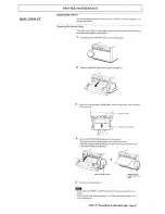
For transportation purposes certain Photo Rides are shipped with their printers removed.  Prior to 
operating the Photo Ride, the printer must be fitted correctly in its printer case.  Use the 
following procedure:- 


a) Completely unwrap your Photo Ride 


    WARNING:-  if your Photo Ride has been shipped with film be careful not to lose the film 


    when disposing of packing material. 


b) Remove the printer from its packing box. 


c) Unlock the metal printer case which is situated towards the front of the ride and pull out the 


    printer tray which is mounted on runners. 


d) Place the printer onto the printer tray. 


e) Connect the following cables to the rear of the printer. 


    (i) connect the mains plug to the mains IEC socket on the rear panel. 


    (ii) connect the 75 OHM coaxial cable with BNC connector to connector marked “video in”. 


    (iii) connect the 3.5mm stereo jack connector to the “remote” connection. 


Now set the DIL switch settings.  Please determine the printer type in use before setting DIL 
switches. 


Sony UP860 


DIL switches 1 & 8 off.  All others on 


Ensure the gamma switch is set to II 


On front panel set THRU/EE switch to EE 


Set Posi-Mega switch to positive 


Sony UP890 


DIL switches 1 & 9 off.  All others on 


Ensure the gamma switch is set to II 


On front panel ensure STD/Side switch is set to Std.  Ensure THRU/EE switch is set to EE. 


Set rotary dial to normal 


f) Place printer into its mounting holes on the tray. 


g) Secure metal strap over top of printer to stop it moving. 


h) Push printer tray back into closed position. 


Chuck ‘E’ Cheese Black & White Photo Ride   Page 1 


Summary of Contents for UP-890CE

Page 1: ...OPERATORS MANUAL CEC B W PhotoRide ...

Page 2: ... to lose the film when disposing of packing material b Remove the printer from its packing box c Unlock the metal printer case which is situated towards the front of the ride and pull out the printer tray which is mounted on runners d Place the printer onto the printer tray e Connect the following cables to the rear of the printer i connect the mains plug to the mains IEC socket on the rear panel ...

Page 3: ......

Page 4: ...seconds For rides fitted with auto cutter see notes on pages 13 14 f If at this stage the picture is i out of focus ii of a poor picture quality i e dark or light adjustment will need to be made to the printer settings or lens This adjustment should be carried out once the Photo Ride is sited in the area in which it is to operate Accurate adjustment to light levels can only be made once the Photo ...

Page 5: ...any risk of damage or tripping f The ride should not be sited in an area where it will cause an obstruction 8 ADJUSTING PICTURE QUALITY Having sited the Photo Ride the picture may need adjustment to quality To ease picture adjustments a monitor taking a PAL input and fitted with a BNC connector is useful and for some adjustments essential For this purpose Amutec strongly recommend the Sony Viewcam...

Page 6: ......

Page 7: ... then the monitor can be disconnected and the printer draw returned Check power is on the printer and close the printer door 9 NORMAL OPERATION OF THE CHUCK E CHEESE PHOTO RIDE 2 COIN a Power up the Photo Ride A message will be heard provided the volume switch is turned up which will state the self test is complete The lights on the toy should flash and power should be on the printer b Insert 1 co...

Page 8: ...he machine 11 INSPECTIONS Every time the ride is emptied check 1 The mains cable and mains plug are in good condition ensuring the fuse is of the correct rating 2 All warning stickers or instruction stickers are in a clean undamaged condition 3 That no sharp edges have been caused by broken lenses or damaged fibreglass 4 Run the machine and check operation is correct Every three months check 1 No ...

Page 9: ...de for signs of wear or damage 10 Remove any build up of rubbish from the ride which may present a fire risk ELECTRICAL EXAMINATION Electrical examination should only be carried out by a suitably qualified electrician who is competent in the testing of portable appliances 1 Check the mains input lead for signs of damage and that correct polarity has been observed 2 Check all electrical connections...

Page 10: ... have been carried out consider whether there are any other issues which could cause the machine to be unsafe to use The above list is only a general guideline and ride inspectors must use their own experience and discretion to ensure that a machine is safe to continue in use When all tests have been carried out the ride should be re assembled and tested using a weight in excess of 51 Kg Ensure th...

Page 11: ...s Coins per Ride Integrated Technology The cost per ride is set at manufacture The cost per ride can be adjusted by 1 replacing the 8 pin IC4 chip with a new one programmed to the desired credit setting 2 using the micromate programmer to re programme the chip IC4 to the desired credit setting The Micromate programmer is an option available at extra cost Coins per Ride Stamar The price per ride ca...

Page 12: ...see paint pantone reference sheet If any fibreglass damage causes a weakening of the fibreglass structure manufacturer s advice should be sought prior to carrying out any repair work Care of Painted Parts The characters on the toys can be maintained by the following method Day to Day Cleaning clean with a damp cloth In the event of damage to paintwork this can be re touched using Amutec touch up p...

Page 13: ......

Page 14: ......

Page 15: ......

Page 16: ......

Page 17: ......

Page 18: ...ed adhesive tape or water based or solid glue Do not stack printed paper on or under a diazo copy sheet The print out may become discoloured SPARE PART ORDERING When ordering spare parts please have available the following information 1 The serial number of the machine 2 The part number required and a description 3 For some parts the supply voltage and coin settings TECHNICAL SPECIFICATION Chuck E...

Page 19: ......

Page 20: ...ed coins then either exit through a chute at the bottom of the acceptor indirect reject or are guided via the return chute 1 5 through the reject slot in the frontplate and come to rest in the u bolt 1 3 The magnet positioned in the magnet side 1 6 of the rundown stops all ferromagnetic blanks These can be stripped clear by the swinging side 1 7 by pressing the reject button 1 4 The anti tilt leg ...

Page 21: ...This is factory adjusted to the correct diameter and should not require field adjustment The microswitch actuating wire should not catch on the side of the black plastic microswitch bracket At its resting position the wire should run along the mid point of a small ridge in the bracket The microswitch is available in three different spring tensions identified by the colour of the plastic boss at th...

Page 22: ...able with meter microswitch bracket or flip flap assembly Features Track adjustable or preset for all coins from 17mm 30mm Coin on cotton catch Washer catcher Diameter thickness and ferrous content check Tests for underweight coins fraud S S front plate with up to 4 entries Reject button and reject outlet Lockout coil wound for most AC and DC voltages Busy B bounce resistant coin microswitch Indir...

Page 23: ... 8 Bulldog Spring 1 9 Slider 1 10 Anti tilt leg 1 11 Washer catcher 1 12 Button Stop 1 13 Fixed Side M Sw Brkt 1 14 Removable Side M Sw Brkt 1 15 Interlock 1 16 Coin guide 1 17 Cradle state coinage 1 18 Cradle weight state coinage 1 19 Microswitch state coinage 1 20 M Sw Screws 2 1 21 Lockout bracket 1 22 Lockout coil state voltage 1 23 Pole piece 1 24 Lockout arm state type 1 25 Lockout spring ...

Page 24: ...1 Orange Munch Sound 2 Purple Jasper Sound 3 Brown Chef Sound 4 Green Red Chuck E Cheese Sound 5 Orange Black Helen Sound Return Reset Return Red Blue Relay Common Low Paper Green Link to Lamp 1 Relay No Low Paper Green Camera Loom Orange Black 12V Camera supply to inner of power connector Black Ov Camera supply Green Low paper light White Low paper light return Auto Cutter Loom Orange Black 12V s...

Page 25: ......

Page 26: ......

Reviews: