background image

SERVICE MANUAL

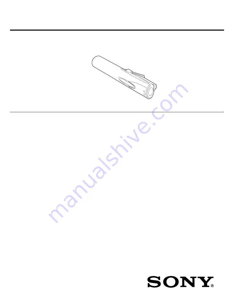
PERSONAL NETWORK PLAYER

AEP Model

SPECIFICATIONS

MC-S50

Ver 1.0  2001.03

9-873-098-11

Sony Corporation

2001C0500-1

Audio Entertainment Group

C

 2001.3

General Engineering Dept.

Audio specifications

Frequency response

20 – 20,000 Hz

Signal-to-noise ratio (S/N)

85 dB

Memory capacity

64 MB (including the system software:

61.1 MB available for music)

Available file format

ATRAC3
MP3

Bit rate*: 32–256 kbps
Sampling rate: 32/44.1/48 kHz

* Variable bit rate files are not

supported. Bit rate higher than 128
kbps is not guaranteed when you
select the sampling rate 32 or 48 kHz.

WMA**

Bit rate: 64–160 kbps

**The files applied with the Microsoft

Windows Media Right Manage are
not supported.

Output

Headphones jack

Stereo mini jack

Connector (special mini jack)

USB 1.0 compliant

General

Power requirements

LR03 (Size AAA) alkaline battery 

×

 1

USB bus power

Battery life

Approx. 6 hours (varies depending on
bit rate, volume, etc.)

Operating temperature

5°C to 35°C (41°F to 95°F) (not
condensed)

Environment temperature

–20°C to 60°C (–4°F to 140°F) (not
condensed)

Supplied accessories

• LR03 (Size AAA) alkaline battery (1)
• Headphones (1)
• Headphones/earphones

extension cord (1)

• Neck strap (1)
• USB cable (1)
• CD-ROM (OpenMG Jukebox

installation disc) (1)

• MC-S50 Operating Instructions (1)
• OpenMG Jukebox Operating

Instructions 

Design and specifications are subject to change
without notice.

(1)

Power consumption

Approx. 145 mW

Dimensions (approx.)

Approx.  22.4 

×

 99.0 

×

 25.9 mm (

29

/

32

×

 4

×

1 inches) (w/h/d)

Mass

Approx. 33g (1.2 oz ) (including
battery)

Summary of Contents for VAIO Music Clip MC-S50

Page 1: ...dows Media Right Manage are not supported Output Headphones jack Stereo mini jack Connector special mini jack USB 1 0 compliant General Power requirements LR03 Size AAA alkaline battery 1 USB bus power Battery life Approx 6 hours varies depending on bit rate volume etc Operating temperature 5 C to 35 C 41 F to 95 F not condensed Environment temperature 20 C to 60 C 4 F to 140 F not condensed Suppl...

Page 2: ...e printed with the lead free mark LF indicating the solder contains no lead Caution Some printed circuit boards may not come printed with the lead free mark due to their particular size LEAD FREE MARK Unleaded solder has the following characteristics Unleaded solder melts at a temperature about 40 C higher than ordinary solder Ordinary soldering irons can be used but the iron tip has to be applied...

Page 3: ...he board block Also when a part on the POWER board was replaced or a combination of LOGIC board and POWER board was changed due to the board replacement perform 1 5 Adjustment When Board was Replaced Repaired 6 The data in Table 1 2 have been written to the LOGIC board 7 In repairing other than above parts repair as usual Table 1 1 Board name Ref No LOGIC board IC601 IC602 IC603 IC901 Table 1 2 Bo...

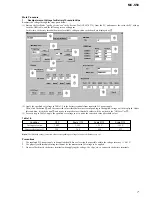
Page 4: ... with a USB cable Check that the block 1 of the following screen open and 1PC is displayed on the LCD of the set The block 1 will close if the set is disconnected again At this time a sine wave is outputted from the headphone Also the model name is displayed in the block qd of the screen Note If the block 1 does not open the circuits in LOGIC board will be faulty Audio signals are outputted from t...

Page 5: ...during the board repair newly set threshold values converted values corresponding to voltage values are displayed Table 1 3 Condition OFF Scale 1 2 Scale 2 3 Scale 3 4 Voltage set value 1 00 V 1 15 V 1 25 V 1 35 V Converted value ref 320 368 400 432 Note The threshold values converted values corresponding to voltage values are different every set 3 LCD Test Clicking FULL full lit COL1 column 1 COL...

Page 6: ...acing the board in this set will cause the status as shown in Table 1 4 Table 1 4 Board name Set status after board replacement LOGIC board Music data and music information data stored in the set are cleared and not restored Precautions 1 Do not disconnect the USB cable in the midway of work 2 If the operation on the PC side is not accepted during work disconnect the USB cable and close the apollo...

Page 7: ...lues corresponding to voltage values are different every set Precautions 1 The regulated DC power supply to be applied should have as less ripple as possible within the voltage accuracy 0 01 V 2 Use properly calibrated measuring instrument for the measurement of voltage to be applied 3 Do not solder directly the battery terminals when applying the voltage Use clips etc to connect to the battery te...

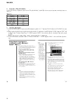
Page 8: ...ile to your Music Clip player Music Clip player can only playback those WMA files that are listed in the Available File Formats in the Options dialog box on Windows Media Player 7 and are of 64 to 160 kbps Notes If you check Enable Personal Rights Management on the CD Audio tab in the Options dialog box when recording a CD using Windows Media Player 7 the music cannot be transferred to Music Clip ...

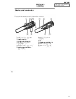
Page 9: ...ay page 11 3 MODE button pages 12 4 N x play stop button page 10 5 buttons pages 11 6 MEGA BASS AVLS button page 13 14 Parts and controls 7 Battery compartment page 7 8 Clip 9 Headphones jack page 10 0 HOLD switch page 15 qa USB connector page 9 Refer to the page numbers indicated in parentheses for details ...

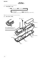
Page 10: ...r given 3 2 CASE ASSY UPPER LOGIC board Display panel liquid crystal LCD901 LOGIC board Audio board Flexible jack board Jack J301 Set Case assy upper Power board 2 lid battery case 9 claw 8 claw 7 claw 6 claw 3 claw 4 claw 5 claw 0 case assy upper 1 screw 1 7 4 Note 1 Use something like a thin board when disconnected claws Note 2 Take care not to damage the cabinet ...

Page 11: ... board 3 4 LOGIC BOARD AUDIO BOARD FLEXIBLE JACK BOARD JACK J301 2 7 screw 1 7 4 8 flexible jack board jack J301 6 AUDIO board 4 LOGIC board 5 connector CN302 3 connector CN301 1 claw case assy lower Note Disconnect the claw warping the case assy lower ...

Page 12: ...MC S50 12 3 5 LOGIC BOARD DISPLAY PANEL LIQUID CRYSTAL LCD901 2 3 LOGIC board 5 BL unit 4 conductive board 6 display panel liquid crystal LCD901 1 Remove two solders LCD case convex ...

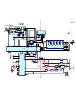
Page 13: ...ASH ROM IC602 RE WE WP CE CE CLE CLE ALE R B ALE R B D0 D7 ADDRESS BUS DATA BUS 2B 2A 2G 2Y3 2Y2 2Y1 2Y0 2 TO 4 DECODER IC604 D0 D7 D0 D7 A0 A7 A0 A7 CE CLE ALE R B HD4 HD0 HD2 HD1 BDR0 IOSTRB BFSX2 BCLKX2 BDR2 BDX2 INT2 INT3 BCLKR1 A0 A7 D0 D7 DIGITAL SIGNAL PROCESSOR IC601 INT1 IS A15 R W RS HD3 X1 X2 CLKIN EEPROM IC603 CS WP SI SO SCK IRQ1 AN0 WKP7 P37 P32 X2 X1 OSC2 OSC1 P90 COM2 COM1 WKP6 WKP...

Page 14: ...nal component C panel designation A B Line Power voltage is dc 1 5V and fed with regulated dc power supply from battery terminal Voltages and waveforms are dc with respect to ground in playback mode no mark PLAYBACK Impossible to measure Voltages are taken with a VOM Input impedance 10 MΩ Voltage variations may be noted due to normal produc tion tolerances Waveforms are taken with a oscilloscope V...

Page 15: ...MC S50 15 15 4 4 SCHEMATIC DIAGRAM LOGIC Board See page 20 for IC Block Diagrams See page 21 for Waveforms Page 19 Page 17 ...

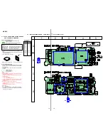
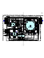
Page 16: ...NG BOARD AUDIO Board Uses unleaded solder B2 E B1 C1 C2 C2 B E1 E2 C1 B C 1 2 3 4 A D101 C 3 D201 C 3 D804 A 4 IC301 C 4 IC302 C 4 Q101 C 3 Q102 A 3 Q201 C 3 Q202 A 3 Q301 A 4 Q302 A 4 Semiconductor Location Ref No Location Page 14 ...

Page 17: ...MC S50 17 17 4 6 SCHEMATIC DIAGRAM AUDIO Board See page 20 for IC Block Diagram See page 21 for Waveforms Page 15 ...

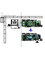
Page 18: ...ded solder Semiconductor Location Ref No Location D401 B 3 D402 A 3 D403 A 3 D405 C 3 D809 B 2 D810 B 3 IC401 B 3 IC402 B 3 IC403 B 3 IC404 B 3 IC405 C 3 IC802 A 3 Q401 B 3 Q402 B 3 Q403 B 3 Q405 A 3 B E C E1 C1 B2 E2 B1 C2 C2 B1 E1 C1 B2 E2 B C 1 2 3 A Page 14 ...

Page 19: ...MC S50 19 19 4 8 SCHEMATIC DIAGRAM POWER Board See page 20 for IC Block Diagrams See page 21 for Waveforms Page 15 ...

Page 20: ...DRIVER LOGIC CHIP SUPPLY FB REF SLOPE COMPENSATION FB REF 40mV OVERVOLTAGE COMPARATOR PWM ON SIGNAL SYNC CELL RAMP GEN REFERENCE VOLTAGE PWM PGND LX SHDN SYNC PWM LIM 10 9 8 7 6 0 1X SENS FET 0 1X SENS FET 5mA 2N PFM ADJ IN PWM PFM CURRENT COMPARATOR LIM COMPARATOR NEGLIM COMPARATOR 12mV 120mV PWM COMPARATOR REF ON PFM COMPARATOR IN BP GND REF FB 1 2 3 4 5 P N IC Block Diagrams POWER Board IC401 M...

Page 21: ...BFSX0 6 IC601 ua BCLKX1 7 IC601 oj X2 CLKIN AUDIO Board 8 IC302 1 LRCK 9 IC302 3 SCLK 0 IC302 5 MCLK POWER Board qa IC401 7 LX qs IC404 9 LX 2 Vp p 30 5 µs 3 2 Vp p 125 ns 3 Vp p 20 8 ns 3 4 Vp p 709 ns 3 4 Vp p 22 7 µs 3 2 Vp p 59 1 ns 1 2 Vp p 59 1 ns 3 4 Vp p 22 7 µs 3 4 Vp p 709 ns 3 2 Vp p 59 1 ns 4 Vp p 13 8 µs 4 Vp p 3 4 µs ...

Page 22: ... strobe signal output to the 2 to 4 decoder IC604 26 MSC O Microstate complete signal output terminal Not used open 27 XF O External flag signal output terminal Not used open 28 HOLDA O Hold acknowledge signal output terminal Not used open 29 IAQ O Instruction acquisition signal output terminal Not used open 30 HOLD I Hold signal input terminal Not used fixed at H 31 BIO I Branch control signal in...

Page 23: ... O Enable signal output to the flash ROM IC602 70 CVSS Ground terminal 71 BCLKX1 O Serial clock signal output to the D A converter IC302 72 DVSS Ground terminal 73 BFSX1 O Serial data receive signal output terminal Not used fixed at H 74 BDX1 O Serial data transmit signal output terminal Not used open 75 DVDD Power supply terminal 3 2V 76 DVSS Ground terminal 77 CLKMD1 I Clock mode signal output t...

Page 24: ...ot used open 120 HD4 O Chip select signal output to the flash ROM IC602 121 to 123 D13 to D15 I O Two way data bus Not used open 124 HD5 O Audio system power ON OFF control signal output terminal H ON 125 CVDD Power supply terminal 1 5V 126 CVSS Ground terminal 127 HDS1 I Data signal input terminal Not used fixed at H 128 DVSS Ground terminal 129 HDS2 I Data signal input terminal Not used fixed at...

Page 25: ...quid crystal display connected to pin qk V2 20 21 COM4 COM3 O Common signal output to the liquid crystal display Not used open 22 23 COM2 COM1 O Common signal output to the liquid crystal display LCD901 24 25 SEG25 SEG24 O Segment signal output to the liquid crystal display Not used open 26 to 40 SEG23 to SEG9 O Segment signal output to the liquid crystal display LCD901 41 WKP7 I USB connection de...

Page 26: ...e last of the electrical parts list NOTE XX and X mean standardized parts so they may have some difference from the original one Color Indication of Appearance Parts Example KNOB BALANCE WHITE RED Parts Color Cabinet s Color 6 24 3 5 14 11 13 13 Ref No Part No Description Remark Ref No Part No Description Remark 3 4 649 908 02 BUTTON PLAY 5 4 649 902 01 WINDOW LCD 6 X 4623 190 1 CASE ASSY UPPER 11...

Page 27: ...1 680 151 11 FLEXIBLE JACK BOARD 69 4 649 895 01 COVER USB 73 A 3323 698 A POWER BOARD COMPLETE 74 A 3323 696 A LOGIC BOARD COMPLETE 75 A 3323 697 A AUDIO BOARD COMPLETE 76 4 649 913 01 RIBBON BATTERY 77 4 649 909 21 LID BATTERY CASE 78 3 228 267 01 SHEET LIGHT INTERCEPTION 79 3 228 357 01 SHEET DSP 80 3 230 336 01 SHEET LARGE ELECTROMAGNETIC 81 3 230 337 01 SHEET SMALL ELECTROMAGNETIC J301 1 815 ...

Page 28: ...P 1uF 20 6 3V C313 1 125 837 11 CERAMIC CHIP 1uF 10 6 3V C314 1 125 777 11 CERAMIC CHIP 0 1uF 10 10V C315 1 125 777 11 CERAMIC CHIP 0 1uF 10 10V CONNECTOR CN301 1 815 120 21 CONNECTOR BOARD TO BOARD 24P CN302 1 815 118 21 CONNECTOR FPC ZIF 5P DIODE D101 8 719 056 59 DIODE MAZS120008SO D201 8 719 056 59 DIODE MAZS120008SO D804 8 719 056 59 DIODE MAZS120008SO FERRITE BEAD FB301 1 469 229 22 FERRITE ...

Page 29: ... D903 8 719 069 29 DIODE RB520S 30TE61 IC IC601 Not supplied IC TMS320DA150GGU120 IC602 Not supplied IC TH58512FTI ELY IC603 Not supplied IC 25LC640XT I ST IC604 8 759 713 60 IC SN74LV139ADGVR IC801 8 759 713 59 IC HD6433800A02FP IC901 Not supplied IC ML60851CLBZ060 LIQUID CRYSTAL DISPLAY LCD901 1 804 249 11 DISPLAY PANEL LIQUID CRYSTAL TRANSISTOR Q901 8 729 037 61 TRANSISTOR UN9113J K8 SO RESISTO...

Page 30: ...071 34 DIODE RB521S 30 TE61 D403 8 719 069 29 DIODE RB520S 30TE61 D405 8 719 069 29 DIODE RB520S 30TE61 D809 8 719 056 59 DIODE MAZS120008SO D810 8 719 056 59 DIODE MAZS120008SO IC IC401 8 759 656 52 IC MAX1674EUA TG069 IC402 8 759 572 21 IC S 80808ANNP E7Y T2 IC403 8 759 530 11 IC S 80809ANNP E7Z T2 IC404 8 759 713 51 IC MAX1692EUB TG069 IC405 8 759 676 78 IC MM1320FNLE IC802 8 759 659 13 IC PST3...

Page 31: ... 792 297 12 CABLE CONNECTION USB 3 226 925 11 MANUAL INSTRUCTION ENGLISH 3 226 925 21 MANUAL INSTRUCTION FRENCH 3 226 925 31 MANUAL INSTRUCTION GERMAN 3 227 797 11 MANUAL INSTRUCTION ENGLISH 3 227 797 21 MANUAL INSTRUCTION FRENCH 3 227 797 31 MANUAL INSTRUCTION GERMAN 3 228 278 21 SOFT CD ROM APPLICATION 4 650 235 01 STRAP NECK 8 953 218 92 RECEIVER EAR MDRE838SP SK1 ...

Page 32: ...ORY Clicking the version allows you to jump to the revised page Also clicking the version at the upper right on the revised page allows you to jump to the next revised page Ver Date Description of Revision 1 0 2001 03 New ...

Reviews: