MC-S50
10
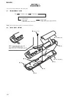
• This set can be disassembled in the order shown below.
3-1.
DISASSEMBLY FLOW
SECTION 3
DISASSEMBLY
Note:
Follow the disassembly procedure in the numerical order given.
3-2.
CASE ASSY, UPPER
“LOGIC board”,
“Display panel, liquid crystal (LCD901)”
“LOGIC board”,
“Audio board”,
“Flexible (jack) board, Jack (J301)”
Set
Case assy, upper
Power board
2
lid, battery case
9
claw
8
claw
7
claw
6
claw
3
claw
4
claw
5
claw
0
case assy, upper
1
screw (1.7
×
4)
Note 1: Use something like a thin board
when disconnected claws.
Note 2: Take care not to damage the cabinet.


