background image

1-10

Confidential

PCG-FX210 (UC)

2

1

2

1

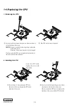
1-4.Replacing the CPU

1. Removing the CPU

2. Installing the CPU

Attach the CPU while

aligning the cut-out with

this position.

1

Insert all pins of the replacement CPU into

the holes of the base and push the CPU in the

direction of the arrow.

2

Insert a screwdriver tip into the groove as shown

and slant it in the direction of the arrow.

The base under the CPU moves slightly in the

direction of the arrow and the CPU is locked.

2

The CPU can be removed upward.

1

Insert a screwdriver tip into the groove as shown and slant it

in the direction of the arrow.

NOTE:

 Do not use screwdrivers having a large tip than the

width of the groove.
Otherwise, it may cause the groove to be damaged.

The base under the CPU moves slightly in the direction of

the arrow and the lock is released.

Summary of Contents for VAIO PCG-FX210

Page 1: ...Confidential PCG FX210 US Model Canadian Model SERVICE MANUAL NOTEBOOK COMPUTER 9 872 204 11 S400 ...

Page 2: ... Inspect after completing service After servicing inspect to make sure that all screws components and wiring have been returned to their original condition Also check the area around the repair location to ensure that repair work has caused no damage and confirm safety 5 When replacing chip components Never reuse components Also remember that the negative side of tantalum capacitors is easily dama...

Page 3: ...el Housing Assy 14 1 inch 1 8 2 Bracket LCD Left Bracket LCD Right LCD Unit 14 1 inch 1 9 3 FPC Inverter Assy Display Housing Assy LCD Harness 1 9 1 4 Replacing the CPU 1 10 1 Removing the CPU 1 10 2 Installing the CPU 1 10 1 5 Replacing Various Connector on the MBX 50 Board 1 11 1 Removing the I O Bracket 1 11 2 Removing the Various Connectors 1 11 1 6 DIP Switch Setting of the MBX 50 Board 1 12 ...

Page 4: ... 2 PC CARD CONNECTOR FDD SPEAKER UNIT DOOR BATTERY SWX 74 BOARD P 1 4 DISPLAY ASSY P 1 2 LITHIUM BATTERY P 1 5 FPC INVERTER ASSY BRACKET LCD LEFT BRACKET LCD RIGHT DISPLAY HOUSING ASSY BEZEL HOUSING ASSY DVD ROM DRIVE LCD UNIT PWS 14 BOARD P 1 5 P 1 5 HDD P 1 8 P 1 9 P 1 9 P 1 9 P 1 9 P 1 9 P 1 9 P 1 9 LCD HARNESS P 1 3 PALM REST PLATE P 1 3 BRACKET PAD P 1 3 TOUCH PAD CNX 129 BOARD P 1 3 MODEM CA...

Page 5: ...he three screws that are built together with the Cooling Unit 2 3 B M2 X2 Silver 9 B M2 Silver 2 B M2 X2 Silver 3Plate ground SH MBX 50 Board CON4 qaLithium Battery Lithium Battery Four Claws 1 B M2 X2 Silver 4 B M2 X2 Silver 8 4 1 MBX 50 Board CON14 6 6Hood Keyboard Assy 7 9 5 q Keyboard Unit Four Claws MBX 50 Board CON21 MBX 50 Board CON15 3M2X4 Special Head Black 8M2X4 Special Head Black 1 2 4P...

Page 6: ... Gold 3Bracket HDD 4FPC 50Pin for HDD 5HDD MBX 50 Board CON9 Palm Rest Assy 1M2X4 Special Head Black 4 3Pull it to the front slightly and raise to remove it 1M2X4 Special Head x4 Black 5Bracket Pad 9Touch Pad 8FPC TP CNX 6FPC SWX PWX 3Palm Rest Plate 2Move down the front portion slightly downward and then pull it out 4Remove by pressing to rear 7CNX 129 Board 2Screw M2 0 Number P3 Kind X4 Black PW...

Page 7: ...enter of the display base facilitates the removal work Four Claws qfCover Hinge qhDisplay Base qg Display Assy 1Stand the LCD upright to the MBX 50 board qaM2X6 Special Head Gold 8Screw M2 0 Number P3 Kind Black 9M2X6 Special Head X2 Gold 5M2 6 Cross Hole Bind Black 7M2 6 Cross Hole Bind Black qs 2 6M2 6 Cross Hole Bind X2 Black q B 2X12 Silver 3 B M2 X2 Gold Six Claws MBX 50 Board CON4 4Plate gro...

Page 8: ...r more details 6PWS 14 Board 3 5Latch Detector 4Two Claws 1 2M2X4 Special Head X2 Black MBX 50 Board CON22 qlMBX 50 Board qaPC Card Connector qsM2 Grip X2 Black q B 2X14 X2 Silver 4 B 2X4 Silver 5Screw MBX Silver qkI O Bracket qjScrew HEX X6 Silevr 9 qd 7Bracket Bay Connector 6M2X4 Special Head X2 Black CON4 qfModem Card 2 qgNUT M2 TYPE2 X2 CPU 1 3M2X4 Special Head X4 Black 1M2X6 Special Head Gold...

Page 9: ...ack 3 1 2 8M2X4 X2 Black 6M2X4 X2 Black SWX 74 Board JP1 SWX 74 Board JP2 SWX 74 Board JP3 Projection Projection Notch Note When removing the speaker unit be sure not to damage the hood keyboard Note To re install it align the notch of the speaker unit with the projection of the hood keyboard Notch b a a a b 2DIMM Door 1M2X4 Special Head Black Removal of SO DIMM ...

Page 10: ...1 7 Confidential PCG FX210 UC 10 Modem Card Removing from the bottom 2Modem Door 4Modem Card 1M2X4 Special Head Black 3M2 Grip X2 Black 5 ...

Page 11: ...l Head X2 Black 2M2X4 Special Head X2 Black 4M2X4 Special Head X5 Black 4M2X4 Special Head X5 Black 5 6 3 9Display Housing Assy Inverter Unit Bezel Housing Assy 8LCD Unit a Bezel Housing Assy Display Housing Assy How to release the claw a Pull the Bezel Housing Assy as shown to release the claw a Order of releasing the claws c b a Order of locking the claws a b c ...

Page 12: ...inch 3 FPC Inverter Assy Display Housing Assy LCD Harness claw part 5M2X4 Special Head 6M2X4 Special Head Black 8Display Housing Assy 4FPC 2Inverter Unit 3 1 7LCD Harness Shield Tape 5LCD Unit 2Bracket LCD Right 4Bracket LCD Left 1Special Head M2x3 X4 Gold 3Special Head M2x3 X4 Gold ...

Page 13: ...p into the groove as shown and slant it in the direction of the arrow The base under the CPU moves slightly in the direction of the arrow and the CPU is locked 2 The CPU can be removed upward 1 Insert a screwdriver tip into the groove as shown and slant it in the direction of the arrow NOTE Do not use screwdrivers having a large tip than the width of the groove Otherwise it may cause the groove to...

Page 14: ...s 901 902 903 904 and 169 refer to page 5 7 remove the I O bracket first 2 Removing the Various Connectors Remove the PC card connector by removing the screws as follows The other connectors Refer to page 5 7 5 8 are connected by soldering remove the soldering first then remove the connectors MBX 50 Board I O Bracket Screw HEX X6 Silver B 2X4 X2 Silver PC Card Connector MBX 50 Board Screw M2 0 Num...

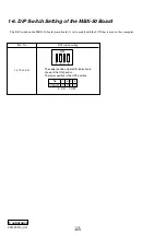
Page 15: ...witch on the MBX 50 board main board is set to match with the LCD that is used in this computer 1 2 3 4 0 0 1 0 0 ON 1 OFF No ON OFF Part No 1 476 166 11 DIP switch setting The upper position where ON indication is shown is the ON position The lower position is the OFF position 1 2 3 4 ON ...

Page 16: ...2 1 PCG FX210 UC Confidential CHAPTER 2 SELF DIAGNOSTICS Please confirm Self Diagnostics method which will be informed you with distribution of Self Diagnostics software ATTENTION END ...

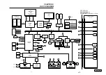
Page 17: ...MB SO DIMM Slot B North Bridge KT133A VT8363 DRAM SIGNAL ADDRESS DATA CTRL SIGNAL CPU AMD Mobile Duron 800MHz Cache 128 64KB L1 L2 FSB 100MHz 462 PIN PGA SOCKET A Graphic ATI 3D RAGE Mobility M1 AGP NTSC PAL TV out LCD Sig TV Sig Cardbus Signal BATTERY 1 USB 0 7 USBP0 Touch Pad BIOS Flash 4Mbit 6 MAX3243 COM SIGNAL Parallel DSUB 25 LPT 4 5 i LINK 4 pin RJ 45 2 LAN Realtek RTL 8139CL LAN RJ 45 2 i ...

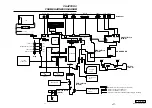
Page 18: ... Speaker L Speaker R CNX 127 Board Side A Rear Panel PHONE PRINTER SERIAL USB NETWORK MONITOR DC IN USB LCD INVERTER HARD DISK FFC LED 1 3 2 1 143 144 1 2 60 59 1 1 1 6 6 1 2 2 1 60 59 2 1 143 144 CON14 CON2 CON22 BCN1 CON7 1 75 150 76 FPC FPC CON10 CON3 BCN4 BCN3 49 50 50 BCN2 1 1 1 12 8 8 PL1 CON6 CON11 CON21 CON15 CON19 CON9 CON23 CON20 18 1 1 1 1 50 25 26 10 2 2 1 50 49 4 99 100 1 CON12 1 2 29...

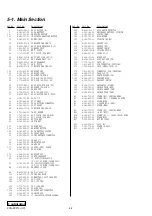
Page 19: ...hould be anticipated when ordering these items When two or more parts are shown in parallel use the part described first as the main part The components identified by mark 0 or dotted line with mark 0 are critical for safety Replace only with part number specified Les composants identifiés par une marque 0 sont critiques pour la sécurité Ne les remplacer que par une pièce portant le numéro spécifi...

Page 20: ... 76 4 644 361 01 BRACKET SPK 78 4 644 362 11 PLATE PALMREST 81 8 749 019 00 IC HYM71V16M655AT6 P PC 100 SO DIMM 128MB CL2 81 8 749 019 88 IC V436516Y04VATG 10PC PC 100 SO DIMM 128MB CL2 84 1 960 827 21 HARNESS 2 PIN 88 A 8025 251 A MBX 50 ASSY S 105 4 641 630 11 COVER BAY HOLE 112 1 815 505 11 CONNECTOR 2 SLOT CARD BUS 123 1 790 711 21 FFC PPK 124 1 757 767 11 FFC TP CNX 125 1 790 710 11 FFC SWX P...

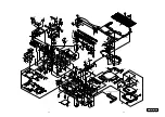
Page 21: ...I J H H A B B A K K L L D 52 112 B4 B4 B1 B32 B8 B4 15 76 76 20 123 20 18 19 21 60 38 183 67 40 3 59 74 164 58 26 25 27 28 124 125 29 81 B1 B33 B33 B1 B1 B8 B8 22 B1 B7 B8 B14 B14 B8 136 136 11 8 134 149 63 71 162 37 36 B6 B6 35 68 53 126 69 J 30 185 186 147 182 180 B8 48 84 148 1 M B1 B1 88 B8 B8 157 154 154 172 B31 B17 M 55 155 B8 105 39 57 56 701 Refer to Page 5 6 168 169 170 181 187 184 184 ...

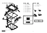
Page 22: ...HEAD B20 7 628 254 00 SCREW PS 2 6X5 B22 4 641 726 81 SCREW M2 SPECIAL HEAD 312 302 307 308 306 305 325 303 B22 B8 304 B8 B8 B20 B20 B22 B8 B8 B8 309 314 322 323 313 313 327 B8 326 B8 317 301 1 319 NOTE The dip switch on the MBX 50 board Main board is set to match with the LCD 1 476 166 11 that is used in this computer The upper position where ON indication is shown is the ON position The lower po...

Page 23: ...r GREEN 901 1 565 999 11 JACK MODULAR 2P Modular jack 902 1 785 976 11 CONNECTOR D SUB PLUG 9P SERIAL connector 903 1 779 499 11 CONNECTOR D SUB 25P PRINTER connector 904 1 779 498 11 CONNECTOR D SUB 15P MONITOR connector 906 1 695 514 31 JACK SMALL TYPE 1P VIDEO OUT connector YELLOW 907 1 793 430 11 JACK SMALL TYPE MICROPHONE connector RED 909 1 785 806 12 CONNECTOR SQUARE TYPE INDI 4P S400 i LIN...

Page 24: ...C This manual and the constituent data may not be replicated copied nor reprinted in whole or in part without prior written authorization of Sony Corporation English 2001E1600 1 2001 Sony Corporation Published by MNC IT Planning Control Dept SODP ...

Reviews: