background image

— 3 —

TABLE OF CONTENTS

CHAPTER 1. REMOVAL

1-1. Flowchart ......................................................................... 1-1
1-2. Main Electrical Parts Location Diagram ......................... 1-1
1-3. Removal ........................................................................... 1-2

1. Hinge Cover ..................................................................... 1-2
2. Keyboard Unit, Palm Rest Assy, Hood Keyboard Assy,

Touch Pad, CNX-125 Board, Palm Rest Plate,
Bracket Pad ...................................................................... 1-2

3. Display Assy,

Combination Drive (CD-RW/DVD-ROM) ...................... 1-3

4. HDD Assy, DC Fan .......................................................... 1-3
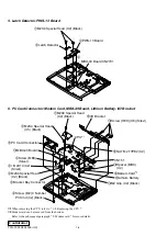
5. Latch Detector, PWS-13 Board ....................................... 1-4
6. PC Card Connector, Modem card, MBX-49 Board,

Lithium Battery, I/O Bracket ........................................... 1-4

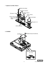
7. Speaker Unit, SWX-73 Board ......................................... 1-5
8. SO-DIMM ........................................................................ 1-5
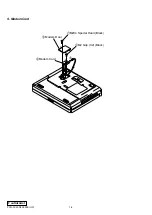
9. Modem Card .................................................................... 1-6

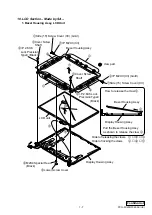
10. LCD Section – Made by SA – ......................................... 1-7

1.Bezel Housing Assy, LCD Unit .................................... 1-7
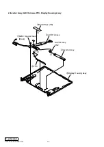
2.Inverter Assy, LCD Harness, FPC,

Display Housing Assy .................................................. 1-8

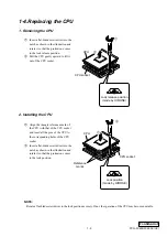
1-4. Replacing the CPU .......................................................... 1-9

1. Removing the CPU .......................................................... 1-9
2. Installing the CPU ............................................................ 1-9

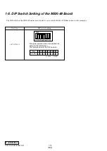
1-5. DIP Switch Setting of the MBX-49 Board .................... 1-10

(to 1-10)

CHAPTER 2. SELF DIAGNOSTICS

.......................... 2-1

(to 2-1)

CHAPTER 3. BLOCK DIAGRAM

............................... 3-1

(to 3-2)

CHAPTER 4. FRAME HARNESS DIAGRAM

........ 4-1

(to 4-2)

CHAPTER 5. EXPLODED VIEWS AND

PARTS LIST

............................................ 5-1

5-1. Main Section .................................................................... 5-2
5-2. LCD Section – Made by SA – ......................................... 5-5

(to 5-6)

Section

Title

Page

Abbreviations
UC : US model / Canadian model

PCG-FX290/FX290K (UC)

Confidential

Summary of Contents for VAIO PCG-FX290

Page 1: ...Confidential PCG FX290 FX290K US Model Canadian Model SERVICE MANUAL NOTEBOOK COMPUTER 9 872 209 11 Illust PCG FX290K S400 ...

Page 2: ...ut 4 Inspect after completing service After servicing inspect to make sure that all screws components and wiring have been returned to their original condition Also check the area around the repair location to ensure that repair work has caused no damage and confirm safety 5 When replacing chip components Never reuse components Also remember that the negative side of tantalum capacitors is easily ...

Page 3: ...4 7 Speaker Unit SWX 73 Board 1 5 8 SO DIMM 1 5 9 Modem Card 1 6 10 LCD Section Made by SA 1 7 1 Bezel Housing Assy LCD Unit 1 7 2 Inverter Assy LCD Harness FPC Display Housing Assy 1 8 1 4 Replacing the CPU 1 9 1 Removing the CPU 1 9 2 Installing the CPU 1 9 1 5 DIP Switch Setting of the MBX 49 Board 1 10 to 1 10 CHAPTER 2 SELF DIAGNOSTICS 2 1 to 2 1 CHAPTER 3 BLOCK DIAGRAM 3 1 to 3 2 CHAPTER 4 F...

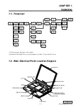
Page 4: ...1 4 P 1 4 PALM REST ASSY P 1 3 DC FAN PC CARD CONNECTOR FDD SPEAKER UNIT SWX 73 BOARD P 1 3 DISPLAY ASSY P 1 4 FPC INVERTER ASSY DISPLAY HOUSING ASSY BEZEL HOUSING ASSY COMBINATION DRIVE LCD UNIT PWS 13 BOARD P 1 4 P 1 3 HDD ASSY P 1 7 P 1 7 P 1 8 P 1 8 P 1 8 P 1 8 LCD HARNESS P 1 2 PALM REST PLATE P 1 2 BRACKET PAD P 1 2 TOUCH PAD CNX 125 BOARD P 1 2 MODEM CARD LATCH DETECTOR I O BRACKET MBX 49 B...

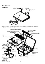
Page 5: ...alm Rest Assy 5 8M2X4 Special Head Black 7Screw M2 0 Number P3 Kind X4 Black PWS 13 Board CN4004 MBX 49 Board CN2004 MBX 49 Board CN1902 1M2X4 Special Head Black 4M2X4 Special Head Black qsM2X4 Special Head x4 Black qhBracket Pad qjTouch pad qfPalm Rest Plate qkCNX 125 Board 2Pull it up sliding it to the right 9Pull it to the front slightly and raise to remove it qdRemove by pulling slightly to th...

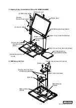
Page 6: ...3 Kind Black 7M2X6 Special Head Gold 2M2X6 Special Head Gold 6M2 6 Cross Hole Bind Black 6M2 6 Cross Hole Bind X2 Black 6M2 6 Cross Hole Bind Black 4 B 2X12 Black 4 B M2 X2 Gold 5Plate Ground Combination Drive CD RW DVD ROM 6DC Fan 5 MBX 49 Board CN102 3HDD Assy 2FPC 50 Pin for HDD 1M2X6 Special Head X6 Gold 4Screw M2 0 Number P3 Kind X4 Black MBX 49 Board CN2201 ...

Page 7: ...graph 9 Modem card for more details 4PWS 13 Board 3 2Latch Detector 1M2X4 Special Head X2 Black MBX 49 Board CN2701 qkMBX 49 Board 9PC Card Connector qdM2 Grip X2 Black 8 B 2X14 X2 Silver 3Screw MBX Silver qjI O Bracket qhScrew HEX X6 Silevr 7 qa 5Bracket Bay Connector 4M2X4 Special Head X2 Black CN151 qfModem Card 2 qsNUT M2 TYPE2 X2 CPU 1 1M2X4 Special Head X2 Black 2M2X4 Special Head X5 Black 6...

Page 8: ... SWX 73 Board 8 SO DIMM 4Speaker Unit 6Hood Keyboard 5SWX 73 Board 4Speaker Unit 2M2X4 X7 Black 1 1 1 3M2X4 X2 Black 3M2X4 X2 Black SWX 73 Board CN303 SWX 73 Board CN301 SWX 73 Board CN302 b a a Removal of SO DIMM a b 2DIMM Door 1M2X4 Special Head Black ...

Page 9: ...1 6 Confidential PCG FX290 FX290K UC 9 Modem Card 2Modem Door 4Modem Card 1M2X4 Special Head Black 3M2 Grip X2 Black 5 ...

Page 10: ...splay Housing Assy a Order of releasing the claws c b a Order of locking the claws a b c Display Housing Assy claw part 1Side 15 Screw Cover X3 Gold 5Lower Screw Cover 3Cover Screw Shaft 3Cover Screw Shaft 4 P 2 6X6 Lock Precision Type3 Black 4 P 2 6X6 Lock Precision Type3 Black 6M2X4 Special Head Black 1Side 15 Screw Cover X3 2 P M2X3 X3 Gold 2 P M2X3 X3 a b 7 0 8 9 b c Bezel Housing Assy LCD uni...

Page 11: ...Confidential PCG FX290 FX290K UC 2 Inverter Assy LCD Harness FPC Display Housing Assy 1 3 2Inverter Assy 9Display Housing Assy Inverter Assy CN2 4FPC 7M2X4 Special Head Black 8LCD Harness 5 6Shield Tape SK ...

Page 12: ...ustration and rotate it so that the protrusion comes to the lock position 1 Insert a flat blade screwdriver into the notch as shown in the illustration and rotate it so that the protrusion comes to the lock release position 2 Pull the CPU gently upward to lift it out of the CPU socket NOTE Rotate a flat blade screwdriver to the lock position securely If not the operation of the CPU may become unst...

Page 13: ...the MBX 49 board main board is set to match with the LCD that is used in this computer Part No 1 476 576 11 DIP switch setting The upper position where ON indication is shown is the ON position The lower position is the OFF position 1 2 3 4 5 6 7 8 O N 1 2 3 4 5 6 7 8 1 0 0 1 0 1 1 1 0 ON 1 OFF No ON OFF ...

Page 14: ...2 1 PCG FX290 FX290K UC Confidential CHAPTER 2 SELF DIAGNOSTICS Please confirm Self Diagnostics method which will be informed you with distribution of Self Diagnostics software ATTENTION END ...

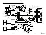
Page 15: ...vices FPC 50pin Multi Purpose Bay FDD 2ndBattery SMBUS2 DVO DVO AHA ATF Sense FAN control ADM1030 FWH Flash BIOS ROM AHA viaLPC Int Keyboard CN FAN Batter1 FW82801 HDD BtoB CN 50pin USB PORT3 LCI SO DIMM Batter2 Refer to Clock Generator Block Diagram FW82801 SMBUS2 GMBUS Debug Board CN BtoB 30pin VDC_IN PCG FX Series BLOCK DIAGRAM Rev 1 00 w Port Replicator PCGA PRFX1 10 10 00 Serial DSUB 9 Parall...

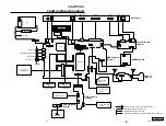
Page 16: ... L Speaker R CNX 123 Board Side A Rear Panel PHONE PRINTER SERIAL USB NETWORK MONITOR DC IN USB LCD INVERTER HARD DISK FFC LED 1 1 2 2 143 144 1 2 1 2 1 1 1 6 6 1 2 59 60 1 2 59 60 143 144 CN102 CN501 CN2701 CN4005 CN1202 1 75 150 76 FPC FPC CN2301 CN2302 CN4001 CN4002 49 50 50 CN4004 1 1 1 12 8 8 CN1502 CN702 CN1801 CN3001 CN1902 CN1401 CN2201 CN2004 CN2602 CN1802 1 1 1 1 1 1 1 25 2 2 2 30 29 50 ...

Page 17: ...ld be anticipated when ordering these items When two or more parts are shown in parallel use the part described first as the main part The components identified by mark 0 or dotted line with mark 0 are critical for safety Replace only with part number specified Les composants identifiés par une marque 0 sont critiques pour la sécurité Ne les remplacer que par une pièce portant le numéro spécifié C...

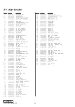
Page 18: ... 709 01 BRACKET IO 74 4 651 702 01 DOOR DIMM 76 4 644 361 01 BRACKET SPK 78 4 644 362 11 PLATE PALMREST 81 8 749 019 00 IC HYM71V16M655AT6 P PC 100 SO DIMM 128MB CL2 84 1 960 827 21 HARNESS 2 PIN 88 A 8066 832 A MBX49 1G ASSY S 105 4 641 630 11 COVER BAY HOLE 112 1 815 505 12 CONNECTOR 2 SLOT CARD BUS 123 1 790 711 21 FFC PPK 124 1 757 767 11 FFC TP CNX 125 1 790 710 11 FFC SWX PWS 126 4 644 053 0...

Page 19: ...1 B32 B8 B8 B8 B17 B4 15 76 76 20 123 20 18 19 21 60 38 67 40 105 39 155 55 3 59 74 58 56 57 26 25 27 28 124 125 29 81 B1 B1 B3 B3 B8 B8 B8 22 B1 B7 B8 B14 B14 B8 136 136 139 11 8 134 63 71 37 36 B6 B29 B29 B6 35 68 53 126 69 32 31 B10 B10 B10 33 B12 J 30 147 81 152 153 164 B8 84 148 1 48 701 Refer to Page 5 6 M B1 M 154 B31 G 156 128 B33 G B12 41 12 not supplied 169 168 170 166 167 ...

Page 20: ...HINGE 15 231 4 643 837 01 SHIELD LCD 234 4 635 276 22 COVER SCREW UPPER 235 4 642 760 12 CUSHION CENTER 236 4 646 216 01 SHIELD TAPE LCD L 237 1 961 017 21 HARNESS LCD SXGA 238 4 650 831 01 SHIELD TAPE SK 239 4 653 980 01 GASKET HINGE 15 B8 4 641 726 11 SCREW M2 SPECIAL HEAD B22 4 642 761 01 P M2X3 LOCK B23 4 644 165 01 SCREW M2 6X4 0 PLATE P1 MAIN B30 4 643 550 01 P 2 6X6 LOCK PRECISION TYPE3 B30...

Page 21: ...0K UC English 2001D1600 1 2001 Sony Corporation Published by MNC IT Planning Control Dept SODP This manual and the constituent data may not be replicated copied nor reprinted in whole or in part without prior written authorization of Sony Corporation ...

Reviews: