background image

2-14

Confidential

PCV-RX7_ _Series (UC)

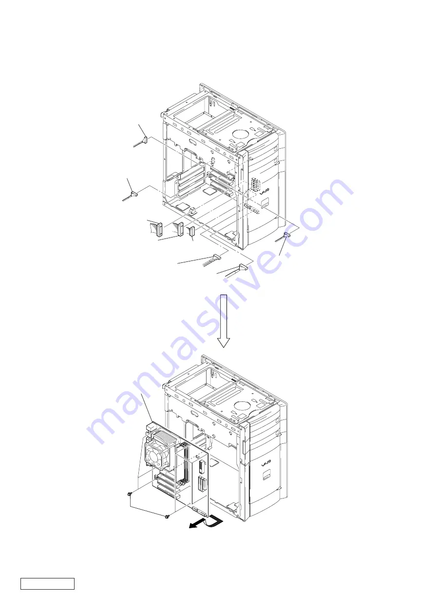
(MOTHER  BOARD  (VA)  ASSY)

A

1

harness
(1394)

3

harness
(IDE CD/DVD)

2

harness
(YUZU AUDIO)

5

harness
(FDD)

4

harness
(IDE/ATA)

6

harness
(USB)

8

harness
(MS, SIO)

7

harness (SW/LED)

0

eight screws
(SW) (No.6-32UNC)

9

Remove the mother board
to direction of arrow 

A

.

Summary of Contents for VAIO PVC-RX700c

Page 1: ...GA DVI VGA PCI PCI PCI Slot3 PCI Slot2 PCI MPEG MPEG Bottom Slot1 PCI Modem PCI Modem CNR Modem CNR Modem CNR Modem CNR Modem CNR Modem CNR Modem CNR Modem CNR Modem CNR Modem CNR MemoryStick a a a a a a a a OS Win XP Home Win XP Home Win XP Home Win XP Home Win XP Home Win XP Home Win XP Home Win XP Home Win XP Home Win XP Home Win XP Home PCV RX743 A2000 AM 512MB 1024MB DDR DIMM PC2100 256MB 80G...

Page 2: ...oth SIG Inc AMD AMD logo AMD Duron and combinations thereof 3DNow are trademarks ofAdvanced Micro Devices Inc Intel Inside logo Pentium and Celeron are trademarks or registered trademarks of Intel Corporation Transmeta the Transmeta logo Crusoe Processor the Crusoe logo and combinations thereof are trademarks of Transmeta Corporation in the USA and other countries Graffiti HotSync PalmModem and Pa...

Page 3: ...CPU 2 12 CPU Installation 2 12 2 21 Mother Board 2 13 3 PROGRAMS FOR SERVICE 3 1 General 3 1 3 2 PC Doctor Starting Method 3 1 3 3 intel815E B Video Diag Starting Method 3 1 4 SERVICE INFORMATION 4 1 Jumper Setting on Hard Disk Drive 4 1 5 FRAME HARNESS 5 1 Connector List 1 Mother Board AM 5 1 2 Mother Board VA 5 3 3 Mother Board KE 5 5 5 2 Frame Harness Diagram and Jumper Setting of Mother Board ...

Page 4: ... PANEL SECTION P2 2 LEFT PANEL SECTION P2 2 OPTICAL DRIVE P2 3 PANEL ASS Y UPPER FOR 2 BAY P2 6 PANEL ASS Y LOWER U P2 7 RIGHT PANEL P2 7 SWX 66 BOARD P2 9 P2 11 MOTHER BOARD P2 13 14 15 SWITCHING POWER P2 3 PCI SLOT PANEL P2 4 VGA CARD P2 5 P2 6 HDD P2 4 FDD P2 9 CPU P2 12 P2 5 MODEM CARD CNX 138 BOARD P2 8 IFX 169 BOARD P2 10 CNX 137 BOARD P2 8 MEMORY MOUNTED PWB ENX 15 ...

Page 5: ...l PCV RX7__Series UC 2 3 LEFT PANEL SECTION 2 2 TOP PANEL SECTION 2 Remove the top panel section in the direction of arrow A A 1 two claws A 2 Remove the left panel section in the direction of arrow A 1 Pull thelever ...

Page 6: ...he direction of arrow C Except DVD RW qd Remove the drive adaptor in the direction of arrow E 2 harness IDE CD DVD 4 harness IDE CD DVD 1 power connector 3 power connector 7 Optical drive upper side qa Optical drive lower side 6 two screws PWH3 5 0 two screws PWH3 5 C B E D 3 bracket power supply ass y 2 Push the lever 5 three screws No 6 32UNC 1 screw No 6 32UNC 6 switching power 4 Disconnect res...

Page 7: ...T PANEL 3 Push the lever 5 two screws SW No 6 32UNC 1 harness IDE ATA 2 power connector 6 HDD 4 HDD bracket ass y 5 two screws SW No 6 32UNC 1 screw SW No 6 32UNC 2 PCI slot panel 5 screw SW No 6 32UNC 3 screw SW No 6 32UNC 6 PCI slot panel 4 PCI slot panel ...

Page 8: ...A CARD 1 screw SW No 6 32UNC 3 VGA card Mother board AM assy Mother board VA assy Mother board KE assy 2 Push the clip AGP 2 Push the clip A 4 Remove the mounted PWB ENX 15 in the direction of arrow A PC12 CN8 CN9 1 harness audio 2 harness audio 3 screw SW No 6 32UNC ...

Page 9: ...ies UC 2 11 PANEL ASS Y UPPER FOR 2 BAY 2 10 MODEM CARD 1 screw SW No 6 32UNC 2 modem card CNR modem PCI modem PCI3 1 screw SW No 6 32UNC 2 modem card 4 panel ass y upper for 2 bay 3 two claws 2 two claws 1 Open the door FDD ass y ...

Page 10: ...__Series UC 2 13 RIGHT PANEL 2 12 PANEL ASS Y LOWER U 4 Remove the front panel ass y lower U in the direction of arrow A 1 two claws 3 two claws 2 two claws A 2 Remove the right panel in the direction of arrow A 1 two claws A ...

Page 11: ...wo screws SW No 6 32UNC A 5 CNX 138 board 1 harness 1394 2 harness USB 3 Remove the bracket AV ass y in the direction of arrow A A 2 harness 1394 1 harness AUDIO 6 CNX 137 board 3 harness USB 5 three screws SW No 6 32UNC 4 Remove the bracket AV ass y in the direction of arrow A ...

Page 12: ...es UC 2 16 SWX 66 BOARD 2 17 FDD 3 SWX 66 board 4 LED shield 2 screws SW No 6 32UNC 1 harness SW LED 4 Remove the FDD bracket ass y in the direction of arrow A A 3 Push the lever 1 harness FDD 2 harness USB 5 two screws PWH3 5 6 FDD ...

Page 13: ...2 10 Confidential PCV RX7__Series UC 2 18 IFX 169 BOARD 3 IFX 169 board 2 claw 1 two screws SW No 6 32UNC ...

Page 14: ...to prevent a drop Note 2 In removing the memories always start from the one having largest bank number 1 Open two clips 2 memory RIMM 4 Note 1 In opening the clips hold lightly the top of the memories with your fingers to prevent a drop Note 2 In removing the memories always start from the one having largest bank number 1 Open four clips 1 Open four clips ...

Page 15: ...on grease is wiped off and silicon compound is applied to the place shown in the figure Thermal diffusion grease silicon compound G 765 90G Amount to apply 0 1 g as the same size as the tip of a match Celeron 0 5 g as the same size as the tip of a match Pentium 4 grease in the surface at the splatter grease in the surface at the splatter Take care not to apply the grease to any other places becaus...

Page 16: ...Series UC 2 21 MOTHER BOARD MOTHER BOARD AM ASSY A 1 harness 1394 2 harness IDE CD DVD 4 harness FDD 3 harness IDE ATA 5 harness USB 6 harness SW LED 7 eight screws SW No 6 32UNC 8 Remove the mother board to direction of arrow A ...

Page 17: ...MOTHER BOARD VA ASSY A 1 harness 1394 3 harness IDE CD DVD 2 harness YUZU AUDIO 5 harness FDD 4 harness IDE ATA 6 harness USB 8 harness MS SIO 7 harness SW LED 0 eight screws SW No 6 32UNC 9 Remove the mother board to direction of arrow A ...

Page 18: ...THER BOARD KE ASSY END A 1 harness 1394 3 harness IDE CD DVD 2 harness YUZU AUDIO 5 harness FDD 4 harness IDE ATA 6 harness USB 8 harness MS SIO 7 harness SW LED 0 eight screws SW No 6 32UNC 9 Remove the mother board to direction of arrow A ...

Page 19: ...rformed to the floppy disk set the DOS formatted 1 44M disk without the write protec tion before the PC Doctor is started Also if the PC Doctor is booted from the CD the boot image of CD is treated as the floppy 0 drive A and accordingly the FDD is treated as the floppy 1 drive B In this case the floppy 0 cannot be tested and N A is displayed as the test result but this is not a fault MISCELLANEOU...

Page 20: ...r Slave Only drive in signal drive system Master drive in dual drive system Slave drive in dual drive system Configuration Jumper Settings Part No Maker Code Capacity Memo formatted A 8110 897 A Seagate ST340810A 40 GB A 8110 895 A Seagate ST360020A 60 GB A 8110 896 A Seagate ST380020A 80 GB Part No Maker Code Capacity Memo formatted A 8059 699 A Maxtor 4G120J6 120 GB Master or single drive Drive ...

Page 21: ... harness diagram AUX Audio 4 pin standard 2mm single line header for AUX Audio signal input Connector location on MB Pin assignments Pin Signal Name 1 Left Line In 2 Ground 3 Ground 4 Right Line In Video Audio not installed 4 pin standard 2mm single line header for AUX Audio signal input Connector location on MB Pin assignments Pin Signal Name 1 Left Line In 2 Ground 3 Ground 4 Right Line In IEEE1...

Page 22: ...ent protector Raychem miniSMDC110 2 or equivalent is used for that See the frame harness diagram See the frame harness diagram USB LAN One USB connectors for external USB devices Support the stacked connector One 10 100Base T connector Connector location on MB Pin assignments Pin Signal Name Pin Signal Name 1 ACTLEDP 11 LANP8 2 ACTLEDN 12 LANP8 3 LILEDP 13 USBVCC1 4 LILEDN 14 USBP1 5 TXPCON 15 UCB...

Page 23: ... Signal Name 1 Ground 2 FAN_CTRL 12 V 3 FAN_SEN Wake On LAN not installed Support Wake On LAN function Connector location on MB See the frame harness diagram Pin assignments Pin Signal Name 1 5Vsb 2 Ground 3 WOL signal CD audio 4 pin standard 2mm single line header for CD Audio signal input Connector location on MB See the frame harness diagram Pin assignments Pin Signal Name 1 Left Line In 2 Grou...

Page 24: ...ck header 8 pin standard 2 0mm dual line header for CNX 169 Memory Stick unit Pin Signal Name 1 2 MS_BS MS LED 3 MS_PWR 4 MS_DIO 5 MS_INS 6 7 8 GND MS_CLK GND VP line need over current protector Raychem SMD150 33 2 or equivalent is used for that PS2 Keyboard Mouse Connector location on MB Rear side See the frame harness diagram PS2VCC line needs the over current protector Raychem miniSMDC110 2 or ...

Page 25: ...4 Right Line In AUX Audio 4 pin standard 2mm single line header for AUX Audio signal input Connector location on MB See the frame harness diagram Pin assignments Pin Signal Name 1 Left Line In 2 Ground 3 Ground 4 Right Line In IEEE1394 access header x2 8 pin standard 2 5mm single line header for IEEE1394 Front connector Connector location on MB See the frame harness diagram Pin assignments Pin Sig...

Page 26: ... frame harness diagram SPDIF Connector location on MB Rear side see the frame harness diagram 3 3 Jumper Header CMOS Clear Clear the RTC data Connector location on MB Jumper header Combination of jumper caps CMOSCLR 1 2 Clear 2 3 Normal 1 2 3 3 2 External connector Parallel Connector location on MB Rear side see the frame harness diagram IEEE1394 Rear connector 6 pin standard IEEE1394 Rear connect...

Page 27: ... CPU FAN CPU CNR1 CNR Connector CNR PANEL J2 J1 MODEM CARD CNR Power Switch HDD LED POWER LED DVD ROM CD RW LED 1394HEAD3 CN1 SOCKET 462 HEATSINK WITH FAN From board to connector direct connection Harness with connectors on both ends Harness soldering on either end 11 20 16 1 10 5 Harness USB20 GALLIA i LINK S400 4 pin USB Harness 1394 CNX 138 BOARD Front Connector CN4 CN3 CN1 CN2 9 8 1 USB23 16 L...

Page 28: ...W LED 1394HEAD3 i LINK S400 4 pin USB CNX 138 BOARD Front Connector CNX 169 BOARD CN4 CN3 CN3 CN2 CN1 CN2 CN1 AGP SOCKET 478 9 8 1 USB23 16 HEATSINK WITH FAN From board to connector direct connection Harness with connectors on both ends Harness soldering on either end MEMORY STICK CONNECTOR PCI2 AUX_CON ENX 15 BOARD CN8 CN13 CN9 CN1 CN2 CN3 L R i LINK S400 4 pin USB VIDEO S VIDEO VIDEO 2 INPUT VID...

Page 29: ... 1 39 40 2 USB FRONT HEATSINK WITH FAN 1 4 1 39 40 2 ATX12V 9 8 1 16 1 2 Clear 2 3 Normal Rear Panel MOUSE KEYBOARD OPTICAL OUT i LINK S400 6 pin PRINTER SERIAL HEADPHONES LINE IN MIC ACT NETWORK LINK CNX 169 BOARD CN1 MEMORY STICK CONNECTOR Harness MS SIO MS_CON EXTENSION HDD AUX_CON From board to connector direct connection Harness with connectors on both ends Harness soldering on either end CN2...

Page 30: ...ring these items 6 1 EXPLODED VIEWS AND PARTS LIST MOTHER BOARD AM ASSY Les composants identifiés par une marque 0 sont critiquens pour la sécurité Ne les remplacer que par une pièce portant le numéro spécifié The components identified by mark 0 or dotted line with mark 0 are critical for safety Replace only with part number specified 59 22 23 19 20 21 24 25 31 32 33 54 52 51 46 24 43 47 50 49 48 ...

Page 31: ...3 19 20 21 24 25 31 32 33 54 52 51 46 24 55 43 11 92 50 49 48 11 2 1 A A 26 11 67 34 60 74 74 74 11 42 11 41 B B 5 5 4 3 53 107 106 28 11 18 39 11 11 16 8 15 12 14 13 6 37 38 11 40 CNX 137 CNX 138 45 Mounted PWB ENX 15 VGA card PCI slot panel PCI slot panel 17 10 95 37 11 93 104 105 58 94 47 108 109 110 ...

Page 32: ...5 6 6 58 59 22 23 19 20 21 24 25 31 32 33 54 46 24 55 43 11 50 103 49 48 11 2 1 A 26 11 67 34 60 74 74 42 11 41 B 5 5 4 3 28 11 39 11 11 16 8 15 12 14 13 6 37 38 11 40 CNX 137 CNX 138 45 Mounted PWB ENX 15 PCI slot panel 17 10 95 37 11 93 104 105 52 51 A 11 B 53 107 106 78 18 92 47 108 110 ...

Page 33: ...O 201 POWER CORD 1 208 CONVERSION CONNECTOR VIDEO CONNECTING 2 203 VIDEO CABLE 1 206 AUDIO CABLE 1 202 ANTENNA CABLE 1 204 KETBOARD 1 205 MOUSE 1 207 MODEM CABLE 1 209 i LINK CABLE 1 210 REMOTE COMMANDER 1 212 RAY CATCHER UNIT 1 211 214 213 215 SPEAKER UNIT 1 216 AC ADAPTOR 1 ...

Page 34: ...4020GU 7 A 17 6 600 087 01 DIMM IC HYMD2646468 H 17 6 600 124 01 DIMM IC M368L6423DTL CB0 17 6 600 127 01 DIMM 256MB IC MT16VDDT3264AG 265B1 z z z z z z z z z z z a 17 6 600 136 01 RIMM 256MB IC MR16R1628AF0 CM8 z a 17 6 702 122 01 DIMM IC V826532K04SATG B0 18 A 8110 924 A MOTHER BOARD AM ASSY S z z z z 18 A 8110 929 A MOTHER BOARD VA ASSY S z a 18 A 8110 930 A MOTHER BOARD VA V ASSY S z z z z z z...

Page 35: ...z z 54 4 640 554 11 CABLE CLAMP z z z z z z z z z z z z z z z z z 55 1 761 570 12 CARD VGA GEFORCE4 MX z z z z 58 4 652 509 11 ESCUTCHEON P DVDRW z z z z z a a 58 4 657 324 71 ESCUTCHEON z z z z z z z z z z a 59 1 796 293 13 DVD ROM P G7 z z z z z z z z z z a 59 1 796 388 12 DVD RW P 104R z z z z a a 59 1 796 388 13 DVD RW P 104R z 60 4 664 067 01 LABEL ID z 60 4 664 068 01 LABEL ID z 60 4 664 070...

Page 36: ... CORD CONNECTION RK G129 z z z z 207 1 783 801 32 CABLE MODEM z z z z z z z z z z z z z z z z z 208 1 790 009 22 CABLE CONNECTOR WITH VIDEO z z z z 209 1 790 145 21 CORD WITH CONNECTOR z z 210 1 476 795 11 REMOTE COMMANDER US z z z z 211 9 885 003 36 LID BATTERY z z z z 212 1 418 887 32 RAY CATCHER UNIT z z z z 215 1 544 899 11 SPEAKER UNIT z z z z z z z 215 1 825 187 11 SPEAKER UNIT z z z z z z z...

Page 37: ...2004B0500 0 2004 Sony Corporation Published by Sony EMCS VAIO GSC C This manual and the constituent data may not be replicated copied nor reprinted in whole or in part without prior written authorization of Sony Corporation PCV RX7__Series AM ...

Page 38: ...First Edition 02 Ver 2 2002 06 27 Model Addition FIT D2002_039 03 Ver 3 2002 07 26 Model Addition FIT D2002_046 04 Ver 4 2004 02 26 FIT D2004_056 FIT D2002_021 FIT D2002_056 FIT D2002_066 FIT D2002_082 FIT D2002_143 FIT D2002_153 FIT D2003_014 FIT D2003_021 FIT D2003_100 Remarks QUICK MEMO reflection ...

Reviews: