3-2
VPH-G90E/G90U/G90M
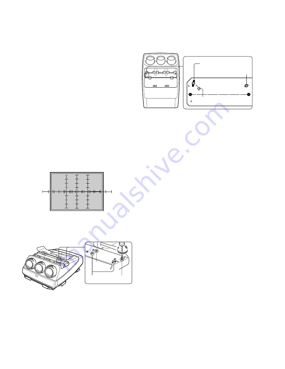
3-3-2. CRT Convergence Angle Check
Open the top cover and check that there are adjusting
screws in the adjusting holes for 120-inch screen. If there
are no adjusting screws in the 120-inch adjusting holes,
adjust as follows.
1. Turn on the power of the projector.
2. Set the remote commander to the serviceman
adjustment mode. For details, see “Remote
Commander” in the instruction manual.
3. Reset the red, green and blue registration data. For
details, see “Resetting the Data” in the instruction
manual.
4. Observe the screen and confirm the following.
.
The center of the green hatch pattern aligns with the
horizontal center of the screen.
.
The centers of the red and blue hatch patterns align at
even intervals from the green hatch pattern.
If the center of the green hatch pattern does not align
with the screen center, the projector may not be
installed correctly. Re-install it rightly.
5. Loosen the CRT fixing screws (two black screws) used
for the red with the use of the supplied tool. Make sure
not to remove the screws.
6. Insert the adjusting screws (two gold screws) in the
adjusting holes for the 120-inch screen.
When the unit is shipped from a factory, the adjusting
screws are screwed into the adjusting holes for 120-
inch screen.
7. Tighten the CRT fixing screws (two black screws) used
for the red, which were loosened at Step 5.
8. Repeat Steps 5 to 7 to loosen the CRT fixing screws
(two black screws) used for the blue, adjust the CRT
convergence angle for the blue, then tighten the CRT
adjustment screws (two gold screws) used for the blue.
120
L
S
Black
screw
Gold screws
Black
screw
120
S
L
for 90” to 300” hole
Move the screw.
for 120” hole
Loosen.
Summary of Contents for VPH-G90E
Page 10: ......
Page 120: ......
Page 122: ...2 2 VPH G90E G90U G90M 2 1 3 Location 3 ME MB MC PB M L MA BA F BC NA BB ...
Page 190: ......
Page 204: ......
Page 210: ......
Page 224: ......
Page 337: ...9 1 9 1 VPH G90E G90U G90M SECTION 9 BLOCK DIAGRAMS ...
Page 363: ...2 3 4 5 A B C D E F G H 1 10 1 10 1 VPH G90J G90E G90U G90M SECTION 10 DIAGRAMS ...
Page 437: ...2 3 4 5 A B C D E F G H 1 10 75 10 75 VPH G90J G90E G90U G90M ...
Page 474: ...2 3 4 5 A B C D E F G H 1 10 112 10 112 VPH G90J G90E G90U G90M ...


