1-35
VPH-G90E/G90U/G90M
Before Installation
8
Installation
Installation
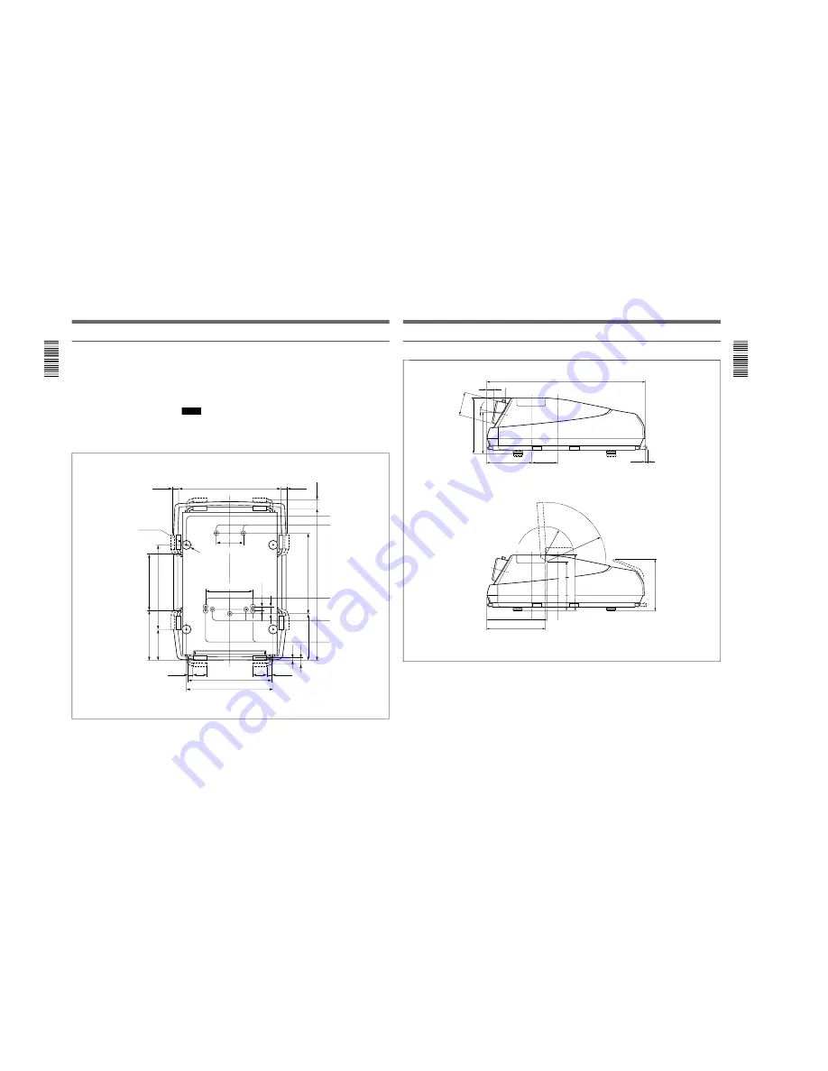
Bottom
The standard hole for installation on the bottom surface is useful for
reference when measuring for installation. There are seven holes on the
bottom surface of the projector. For ceiling installation using the optional
PSS-90 Projector Suspension Support, use five holes to attach the PSS-90.
The other two holes are spare ones.
Notes
• Use only the M8 meter screws of 10 mm (
13
/
32
inches) to 30 mm (1
3
/
16
inches) long for the attachment holes for the PSS-90.
• When attaching the PSS-90, use the M8 meter screws of 20 mm (
25
/
32
inches) supplied with the PSS-90.
Unit: mm (inches)
Hole for attaching an
adjuster
(M10 meter screw,
Max 30 mm (1
3
/
16
inches))
679 (26
3
/
4
)
Spare holes for
installation
40 (1
5
/
8
)
Holes for attaching
the PSS-90
(M8 meter screws,
20 mm (
25
/
32
inches))
Receptacles for the
projections on the PSS-
90 (Standard hole for
installation)
40 (1
5
/
8
)
179 (7
1
/
8
)
340.5 (13
1
/
2
)
322 (12
3
/
4
)
211.5 (8
3
/
8
)
384 (15
1
/
8
)
573 (22
5
/
8
)
4-
∅
60
308.5
(12
1
/
4
)
547 (21
5
/
8
)
1031.6 (40
5
/
8
)
50 (2)
90
(3
5
/
8
)
35 (1
7
/
16
)
90
(3
5
/
8
)
35 (1
7
/
16
)
550 (21
3
/
4
)
580 (22
7
/
8
)
16.5 (
21
/
32
)
50 (2)
Holes for attaching
the PSS-90
(M8 meter screws,
20 mm (
25
/
32
inches))
Installation
9
Installation
Side
With the covers open
Location of the standard hole for installation
Center of projection balance
R 411
(16
1
/
4
)
Center of projection balance
11.9
°
Location of the standard
hole for installation
1066 (42)
∅
157.5
(6
1
/
4
)
385.5 (15
1
/
4
)
289 (11
1
/
2
)
308.5 (12
1
/
4
)
168
(6
5
/
8
)
16.5 (
21
/
32
)
Unit: mm (inches)
354 (14)
401.2 (15
7
/
8
)
415.8 (16
3
/
8
)
R 196
(7
3
/
4
)
340 (13
1
/
2
)
385.3 (15
1
/
4
)
Summary of Contents for VPH-G90E
Page 10: ......
Page 120: ......
Page 122: ...2 2 VPH G90E G90U G90M 2 1 3 Location 3 ME MB MC PB M L MA BA F BC NA BB ...
Page 190: ......
Page 204: ......
Page 210: ......
Page 224: ......
Page 337: ...9 1 9 1 VPH G90E G90U G90M SECTION 9 BLOCK DIAGRAMS ...
Page 363: ...2 3 4 5 A B C D E F G H 1 10 1 10 1 VPH G90J G90E G90U G90M SECTION 10 DIAGRAMS ...
Page 437: ...2 3 4 5 A B C D E F G H 1 10 75 10 75 VPH G90J G90E G90U G90M ...
Page 474: ...2 3 4 5 A B C D E F G H 1 10 112 10 112 VPH G90J G90E G90U G90M ...


