1-48
VPH-G90E/G90U/G90M
34
Connections
Connections
Using the PC-3000 Signal Interface Switcher
Setting up
• Set the device index number of the projector to “01”
(page 142).
• Set the switcher number of the switcher which is connected directly to the
projector to “1,” and that of the second switcher to “2,” and so on.
For details, refer to the Operating Instructions of the switcher.
• When using the remote commander as a wireless remote control, activate
the remote control detector of a piece of the equipment in the system only
and deactivate those of the other equipment. Perform the setting on the
projector using “SIRCS RECEIVER” in the SET SETTING 2 menu
(page
63)
.
For setting on the switcher, refer to the Operating Instructions of the switcher.
Connections
35
Connections
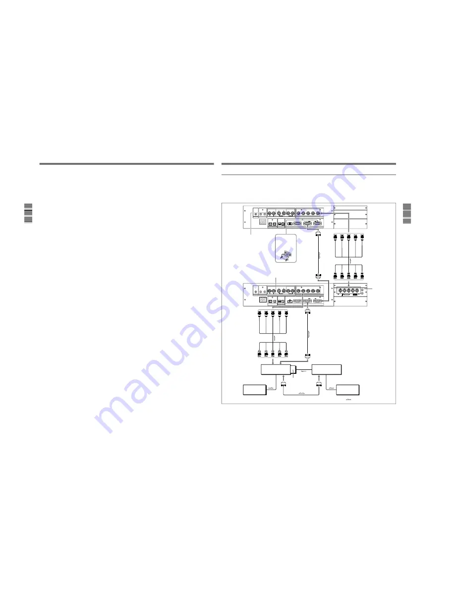
Connecting multiple projectors using the PC-3000 switcher(s)
This is an example to connect multiple projectors and two PC-3000
switchers.
Install the IFB-12/12A Signal Interface Board to the INPUT B section of
the first projector.
TRIGGER
LINK
R-Y/PR
R
B-Y/PB
G
B
SYNC/HD
VD
INPUT A
Y
CONTROL S
PLUG IN POWER
DEVICE INDEX
IN
OUT
IN
OUT
REMOTE
RS-232C/422A
RS-232C RS-422A
IN
OUT
TRIGGER
LINK
R-Y/PR
R
B-Y/PB
G
B
SYNC/HD
VD
INPUT A
Y
CONTROL S
PLUG IN POWER
DEVICE INDEX
IN
OUT
IN
OUT
REMOTE
RS-232C/422A
RS-232C RS-422A
IN
OUT
PJ COM
R/P
R
B/P
B
SYNC/HD
VD
L
R
AUDIO
(MONO)
1 2 3 4 5 6
OUT
IN
R-Y/VIDEO
Y/Y
B-Y/C
ON
PJ COM
S VIDEO
OUT
IN
C IN
Y IN
VIDEO
VIDEO
IN
OUT
S VIDEO
OUT
IN
C IN
Y IN
VIDEO
VIDEO
IN
OUT
PJ COM IN
PJ COM OUT
R
G
B
SYNC/HD
VD
R
G
B
SYNC/HD
VD
INPUT A
Second
projector
Attach the
supplied
terminator.
5BNC cable
First
projector
First switcher
PC-3000
5BNC cable
to OUTPUT
to
OUTPUT
to
IN
to PJ COM OUT
PJ COM OUT
PJ COM IN
Second switcher
PC-3000
Computer
Computer
IFB-12/12A
Signal Interface
Board
Signal flow
to PJ COM
IN
to PJ COM
OUT
INPUT A
IFB-12/12A
Signal
Interface
Board
(optional)
*
*
For the VPH-G90 model:
IFB-G90E Video Interface Board (optional).
*
(continued)
Summary of Contents for VPH-G90E
Page 10: ......
Page 120: ......
Page 122: ...2 2 VPH G90E G90U G90M 2 1 3 Location 3 ME MB MC PB M L MA BA F BC NA BB ...
Page 190: ......
Page 204: ......
Page 210: ......
Page 224: ......
Page 337: ...9 1 9 1 VPH G90E G90U G90M SECTION 9 BLOCK DIAGRAMS ...
Page 363: ...2 3 4 5 A B C D E F G H 1 10 1 10 1 VPH G90J G90E G90U G90M SECTION 10 DIAGRAMS ...
Page 437: ...2 3 4 5 A B C D E F G H 1 10 75 10 75 VPH G90J G90E G90U G90M ...
Page 474: ...2 3 4 5 A B C D E F G H 1 10 112 10 112 VPH G90J G90E G90U G90M ...


