background image

12

Connecting to Video Equipment or a 
Computer

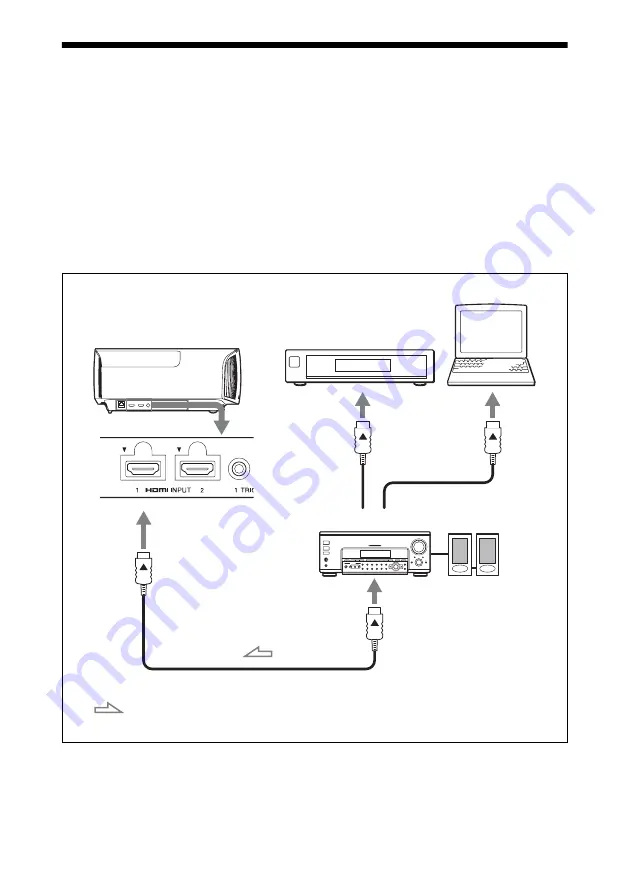
You can enjoy high picture quality by connecting a DVD player/recorder, Blu-ray Disc player/
recorder, or PlayStation

®

 equipped with HDMI output to the HDMI input of the unit.

When making connections, be sure to do the following:

• Turn off all equipment before making any connections.
• Use the proper cables for each connection.
• Insert the cable plugs properly; poor connection at the plugs may cause a malfunction or poor 

picture quality. When pulling out a cable, be sure to pull it out from the plug, not the cable 
itself.

• Refer to the operating instructions of the connected equipment.

Right side of the unit

AV amplifier

Speakers

Equipment with HDMI 
output connectors

Computer

to HDMI output

HDMI cable (not supplied)

: Video signal flow

Use a Premium High Speed HDMI cable on which the cable 
type logo is specified.

Summary of Contents for VPL-VW570ES

Page 1: ...Operating Instructions Before operating the unit please read this manual and supplied Quick Reference Manual thoroughly and retain them for future reference VPL VW570ES 4 743 476 01 1 Video Projector ...

Page 2: ...tallation Menu 38 Information Menu 41 About the Preset Memory 41 Using Network Features Displaying the Control Window of the Unit with a Web Browser 42 Operating the Control Window 43 Switching the Page 43 Setting the Access Limitation 43 Confirming the Information Regarding the Unit 44 Error Handling Troubleshooting 45 Warning Indicators 48 Message Lists 49 Others Updating the Software 50 About H...

Page 3: ...or page 12 e TRIGGER 1 TRIGGER 2 connector page 38 f IR IN connector Inputs signals to control the unit g REMOTE connector Connects to a computer etc for remote control h USB connector page 50 Others i Lamp cover page 51 j Ventilation holes exhaust k Ventilation holes intake page 53 l Remote control detector page 7 Location of Controls Warning indicators ...

Page 4: ...a 1 ON STANDBY button page 7 b INPUT button page 14 c MENU button page 22 d M m arrow enter button page 22 e LENS button page 7 Others f Remote control detector page 7 g Ventilation holes intake page 53 h AC IN socket page 7 i Projector suspension support attaching hole page 69 j Front feet adjustable page 10 Control panel ...

Page 5: ...utton page 16 h RESET button page 23 i M m arrow enter buttons page 22 j MENU button page 22 k MOTIONFLOW button page 26 l ASPECT button page 18 m COLOR SPACE button page 29 n COLOR TEMP button page 27 o GAMMA CORRECTION button page 28 p 3D button page 15 q REALITY CREATION button page 25 r ADVANCED IRIS button page 25 s CONTRAST ENHANCER button page 25 t SHARPNESS button page 27 u CONTRAST button...

Page 6: ...ance and the size of projected video see Projection Distance and Lens Shift Range page 64 1 Position the unit so that the lens is parallel to the screen Top view 2 Project an image on the screen and adjust the picture so that it fits the screen page 7 When using a screen with an uneven surface stripes pattern may rarely appear on the screen depending on the distance between the screen and the unit...

Page 7: ...n switches between Lens Focus Lens Zoom and Lens Shift Depending on the installation location of the unit you may not be able to control it with the remote control In this case point the remote control at the remote control detector of the unit or the screen 1 After connecting the AC power cord to the unit plug the AC power cord into a wall outlet The ON STANDBY indicator lights in red and the uni...

Page 8: ...38 When Test Pattern is set to Off on the Function menu the test pattern is not displayed page 36 Adjust the lens by using buttons on the remote control or the control panel of the unit Never make adjustments by directly turning the lens with your hands which may cause damage or malfunction to the unit 4 Adjust the picture size Press the LENS ADJUSTMENT ZOOM button to display the Lens Zoom adjustm...

Page 9: ...hed by the moving parts To adjust the horizontal position Press The picture projected on the screen moves right or left by a maximum of 31 of the screen width from the center of the lens Top view Press the RESET button on the remote control while the Lens Shift adjustment window is displayed the horizontal position returns to the center of the lens factory default position The zoom and focus are n...

Page 10: ... projected picture To adjust the tilt of the installation surface If the unit is installed on an uneven surface use the front feet adjustable to keep the unit level If the unit is tilted up or down the projected image may be trapezoidal Be careful not to catch your finger when turning the front feet adjustable Note 85 80 1 screen height Picture position when moving the picture upward at maximum Pi...

Page 11: ...11 Lens adjustment window test pattern 1 78 1 16 9 2 35 1 1 85 1 1 33 1 4 3 The dashed lines show the screen sizes of each aspect ratio ...

Page 12: ... Use the proper cables for each connection Insert the cable plugs properly poor connection at the plugs may cause a malfunction or poor picture quality When pulling out a cable be sure to pull it out from the plug not the cable itself Refer to the operating instructions of the connected equipment Right side of the unit AV amplifier Speakers Equipment with HDMI output connectors Computer to HDMI ou...

Page 13: ...om equipment connected to the unit with an HDMI cable is not correct check the settings of the connected equipment If you set your computer such as a notebook type to output the signal to both computer s display and this equipment the picture of the equipment may not appear properly Set your computer to output the signal to only the external monitor For details refer to the computer s operating in...

Page 14: ... POWER OFF appears on the screen 2 Press the 1 ON STANDBY button again before the message disappears The ON STANDBY indicator flashes in green and the fan continues to run to reduce the internal heat The fan stops and the ON STANDBY indicator changes from flashing green to remaining red The power is turned off completely and you can disconnect the AC power cord Never disconnect the AC power cord w...

Page 15: ...ion range page 15 There are differences in perception of 3D video images among individuals When the temperature of the usage environment is low the 3D effect may be diminished Adjusting Setting the 3D functions You can adjust set the 3D functions by pressing the 3D button on the remote control or with the 3D Settings of the Function menu For details see 3D Settings page 35 1 Turn on the 3D glasses...

Page 16: ... Position is not stored 1 Press POSITION The Picture Position selecting palette is displayed 2 Press POSITION repeatedly or press M m to select the position The settings of the position selected is recalled Store or delete lens settings aspect ratio and blanking in the Picture Position of the Screen menu page 31 The position where the lens settings aspect ratio and blanking are not stored is displ...

Page 17: ...s In this case select the lens position again or adjust the lens manually The Picture Position function is not guaranteed to reproduce the lens settings precisely When you use the subtended screen angle of two or more aspects using lens zoom install the unit within the specified parameters referring to Projection distance page 65 With some setting positions the range of lens shift may be restricte...

Page 18: ...uited for the video signal received Press ASPECT Each time you press the button you can select the Aspect setting You can also select it using the menu page 32 ASPECT button Original image Recommended setting and resultant images 1 85 1 Squeezed 1 85 1 1 85 1 Zoom 2 35 1 Squeezed 2 35 1 2 35 1 Zoom ...

Page 19: ... Original image Recommended setting and resultant images 1 78 1 16 9 1 33 1 4 3 1 33 1 4 3 with side panels Normal 2 35 1 V Stretch When using an anamorphic lens 16 9 Squeeze When using an anamorphic lens ...

Page 20: ...ount that changing the aspect ratio of the original picture will provide a different look from that of the original image Note that if the unit is used for profit or for public viewing modifying the original picture by switching the aspect may constitute an infringement of the rights of authors or producers which are legally protected Original image Recommended setting and resultant images Squeeze...

Page 21: ...A picture quality setup suitable for when you want to reproduce faithfully the original image quality or for enjoying image quality without any adjustment TV Picture quality suited for watching TV programs sports concerts and other video images PHOTO Ideal for projecting still images taken with a digital camera GAME Picture quality suited to gaming with well modulated colors and fast response BRT ...

Page 22: ...th setting items appears 1 Press MENU The menu window appears 2 Press M m to select a menu item and press or The items that can be set or adjusted with the selected menu appear The item presently selected is shown in white 3 Press M m to select an item you want to set or adjust and press or The setting items are displayed in a pop up menu in a setting menu in an adjustment menu or in the next menu...

Page 23: ...elect Reset from the Picture menu When the screen display appears select Yes using and press All of the following settings are reset to its factory preset value Reality Creation Cinema Black Pro Motionflow Contrast Brightness Color Hue Color Temp Sharpness and Expert Setting on the Picture menu To reset the items that have been adjusted Select an item in the menu screen and display the pop up menu...

Page 24: ...lity setup suitable for when you want to reproduce faithfully the original image quality or for enjoying image quality without any adjustment TV Picture quality suited for watching TV programs sports concerts and other video images Photo Ideal for projecting still images taken with a digital camera Game Picture quality suited to gaming with well modulated colors and fast response Bright Cinema Pic...

Page 25: ...perture and signal processing according to the brightness level of the input source This results in a bright and high contrast image Limited Provides a slower movement of the iris aperture and lower brightness than Full making the picture quality suitable for viewing in a dark room Off The Dynamic Control function is not applied Brightness The higher the setting the brighter the picture The lower ...

Page 26: ...t visually even if you have changed the settings Contrast CONTRAST Adjusts the contrast Higher values increase the sharpness in images while lower values decrease the sharpness You can make adjustments by pressing the CONTRAST on the remote control When the HDR signal is input with HDR10 HDR Reference HLG or Auto set for HDR Contrast HDR appears instead of Contrast Brightness BRIGHTNESS Adjusts th...

Page 27: ...u can make adjustments by pressing the SHARPNESS on the remote control Expert Setting NR Noise Reduction Reduces the roughness or noise of the picture Auto Detects the noise level to reduce the roughness or noise of the picture automatically High Middle Low Select a setting according to the roughness or noise of the input signal source Off The NR noise reduction function is not applied Tip The noi...

Page 28: ...when you watch TV programs etc in a bright environment such as a living room Off The Gamma Correction function is not applied Color Correction On Adjusts Hue Saturation or Brightness of the selected colors Repeat steps 1 and 2 described below to specify the target color 1 Press M m to select Color Select then press to select the color you want to adjust among Red Yellow Green Cyan Blue and Magenta...

Page 29: ...ts Color Space COLOR SPACE Converts the color space BT 709 An ITU R BT 709 color space which is used for high definition television broadcast or Blu ray Disc The color space is equivalent to sRGB BT 2020 The color space is wider than BT 709 Use this setting when playing back HDR content Color Space 1 The color space suited for watching TV programs and video images such as sport concerts etc Color ...

Page 30: ...akes a few minutes for Pre Check or Adjust to complete When Pre Check or Adjust starts the screen position may shift as the lens returns to its factory default position After completion the screen returns to its previous position automatically If the environment changes such as the brightness of the room while performing Pre Check or Adjust measurement may be affected If the Pre Check or Adjust fu...

Page 31: ...d 1 85 1 2 35 1 Custom 1 Custom 2 or Custom 3 in the display change to Select Recalls the settings of the selected position Tips The optimal aspect ratio is preset for each picture position The aspect ratio can be changed and saved for each picture position When saving the Picture Position temporarily move the picture from the saving point down 5 cm or more Move the picture up again and save This ...

Page 32: ...lable anamorphic lens When you select V Stretch from Trigger Select 1 2 on the Installation menu a 12 V signal is output from the TRIGGER 1 or TRIGGER 2 connector page 38 Squeeze With this setting 1 78 1 16 9 and 1 33 1 4 3 video will be displayed in their correct aspect ratios when you use a commercially available anamorphic lens Stretch Displays video that has been squeezed to 1 33 1 4 3 as 1 78...

Page 33: ...he unit at an altitude of 1 500 m approx 4 900 ft or higher Off Use this setting when using the unit at normal altitudes Tip When this item is set to On the fan noise becomes slightly louder since the fan speed increases Remote Start Sets the Remote Start settings On You can turn on the power from a PC or a terminal which is connected to a network Off Turns off the Remote Start function Tips To us...

Page 34: ...the network If you set to On the power consumption increases Power Saving Sets the power saving mode Standby If no signal is input for 10 minutes power is turned off automatically and the projector goes into standby mode Off Disables the power saving function Lamp Setting When replacing the lamps set the desired lamp setting page 51 All Reset All settings are initialized to their factory preset va...

Page 35: ...scriminate 3D and some HDMI signals have none 3D Format Set the 3D system when the input HDMI signals do not include 3D information Simulated 3D Converts 2D video images to 3D video images The setting can be made only for input the HD signals The simulated 3D feature may have limited effect depending on the video source There are differences in perception of 3D video images among individuals Side ...

Page 36: ...ectly light and dark parts of the video may appear too light or too dark HDMI Signal Format Switches the video signal formats for 4K Standard Format Displays a picture in the standard HDMI format Enhanced Format Displays a picture in a more detailed HDMI format Tips A picture or sound may not be output normally when Enhanced Format is selected In this case set to Standard Format It may take time t...

Page 37: ...on Film Mode Gamma Correction Color Correction Clear White x v Color HDR Color Space Input Lag Reduction Advanced Picture menu Auto Calibration Setup menu Status Language Menu Position High Altitude Mode Remote Start Network Management Power Saving Lamp Setting Function menu Dynamic Range Test Pattern Installation menu Image Flip Lens Control Anamorphic Lens Trigger Select IR Receiver Panel Alignm...

Page 38: ...phic lens with a horizontal rate of 1 24 1 32x Select this when you use an anamorphic lens with a horizontal rate of 1 32 Trigger Select Switches the output function of the TRIGGER 1 TRIGGER 2 connector Off Turns off the TRIGGER connector function Power Outputs 12 V signals from the TRIGGER 1 TRIGGER 2 connectors when the unit is on The TRIGGER 1 TRIGGER 2 connectors do not output any signals when...

Page 39: ...B Blue Adjust The shift adjustment and zone adjustment of the color selected in Adjust Color can be made with M m buttons When Shift is selected Assign the settings of the horizontal direction H with buttons and the vertical direction V with M m buttons on the shift adjustment screen When Zone is selected Select the position to adjust with buttons for the horizontal position H position and M m but...

Page 40: ...hen press button Select the frame to input with the buttons and input the value with the M m buttons When all items are entered select Apply and then press the button The entered settings will be registered IP Address Sets the unit s IP address Subnet Mask Sets the unit s subnet mask Default Gateway Sets the unit s default gateway MAC Address Displays the unit s MAC address This cannot be changed ...

Page 41: ... the computer input signal parts of screen may be hidden or displayed incorrectly Items Description Model Name Displays the model name Serial No Displays the serial number Signal type Displays the resolution of the input signal which you are selecting When input signals with 3D information are input the type of input signals and the 3D format are displayed Color Format Displays the color format of...

Page 42: ... you are using Supported Web browsers are Internet Explorer 8 9 10 11 The menu displays only English If the browser of your computer is set to Use a proxy server when you have access to the unit from your computer click the check mark to set accessing without using a proxy server AMX DDDP is not compatible with IPv6 These network functions are available when the unit is turned on Displaying the Co...

Page 43: ...ed access to all pages User Allowed access to all pages except the Setup page When you access the Setup page for the first time input root as the user name and Projector as the password in the authentication dialog When you log in for the first time the window that prompts you to change the password is displayed Follow the instructions on the screen to change the password The name of the administr...

Page 44: ...t and numeric characters Alphabet is case sensitive The default password Projector cannot be set as a new password If you forget your password consult with qualified Sony personnel The password will be reset with your permission You can confirm the current settings for the unit on the Information page Note Confirming the Information Regarding the Unit Entry area for Administrator Entry area for Us...

Page 45: ...that the computer signal is set for output to an external monitor If the notebook computer etc signal is output to its display and an external monitor the external monitor s image may not be displayed correctly Set your computer to output the signal to only an external monitor The picture has ghosts Video images are displayed in 3D Watch the 3D video images using the 3D glasses and set 2D 3D Displ...

Page 46: ...TANDBY indicator should light in green When the ON STANDBY indicator blinks in green the unit is starting up Wait until it stops blinking and remains lit in green 7 The model name does not disappear from the screen The display mode of the unit may be set at the time of purchase Consult with your local dealer or qualified Sony personnel Symptom Cause and Remedy Page The remote control does not work...

Page 47: ...D glasses may not be able to display the images properly 15 The screen size is not appropriate Set the zooming magnification to low or watch the image from farther away from the screen 64 For details see Precautions for use of Using the 3D Glasses 15 Symptom Cause and Remedy Page The fan is noisy Check the setting of High Altitude Mode on the Setup menu 33 Make sure that the room temperature is no...

Page 48: ...lashes Cause and Remedy Twice Close the lamp cover securely then tighten the screws securely page 52 Three times The temperature of lamp is unusually high Turn off the power and wait for the lamp to cool then turn on the power again If the symptom persists the lamp may be at the end of its service life In this case replace the lamp with a new one page 51 Twice The internal temperature is unusually...

Page 49: ...erature is high High Altitude Mode should be On if projector is being used at high altitude Check to ensure that nothing is blocking the ventilation holes 3 4 When using the unit at high altitude set High Altitude Mode to On When temperature inside the unit remains high High Altitude Mode is switched to On in 1 minute then the fan speed increases 33 Power Saving Mode is set Projector will automati...

Page 50: ...HDR high dynamic range HDR is a video expression which improves the ability to express dark places and bright places compared to previous video expressions About the simulated 3D feature Use the simulated 3D function taking into account that the picture will provide a different look from the original images because this function converts the video images Note that if the unit is used for profit or...

Page 51: ... when the unit is installed on the ceiling When replacing the lamp of a unit which is on the ceiling do not stand directly under the lamp cover When removing the lamp door inner cover avoid twisting it If the lamp explodes fragments may cause injury When removing the lamp unit make sure it remains horizontal then pull straight up Do not tilt the lamp unit If you pull out the lamp unit while tilted...

Page 52: ...s except the 3 specified screws Hold the lamp by the handle to remove and attach it 6 Push in the new lamp by the handle securely until it reaches the end and then tighten the 3 screws Be careful not to touch the optical block inside the unit 7 Close the lamp door inner cover and then tighten the screw 8 Close the lamp cover Notes Handle Note ...

Page 53: ...l not turn on unless the lamp cover are securely closed To clear a message displayed on the screen press any button either on the remote control or the control panel of the unit once Note on replacing the lamp when broken in the case of a ceiling installation If the lamp breaks broken lamp pieces may scatter and cause injury When the unit is on the ceiling remove the lamp door inner cover by slidi...

Page 54: ...gent solution Never use any type of abrasive pad alkaline acid cleaner scouring powder or volatile solvent such as alcohol benzene thinner or insecticide Clean the unit with a cleaning cloth Wiping with a dirty cloth may scratch the unit Using such materials or maintaining prolonged contact with rubber or vinyl materials may result in damage to the screen surface and cabinet material ...

Page 55: ... IR IN Minijack USB DC 5 V Max 500 mA Outside dimensions w h d 495 6 mm 205 3 mm 463 6 mm 19 1 2 8 3 32 18 1 4 inches without protrusions Mass Approx 14 kg 31 lb Power requirements AC 100 V to 240 V 4 6 A to 2 0 A 50 60 Hz Power consumption 460 W Power consumption Standby 0 4 W when Remote Start is set to Off Networked Standby 1 0 W LAN when Remote Start is set to On When a LAN terminal is not con...

Page 56: ...rogressive PAL 720 576p 31 250 50 000 7 1080 60i 1080 60i 1920 1080i 33 750 60 000 8 1080 50i 1080 50i 1920 1080i 28 130 50 000 10 720 60p 720 60p 1280 720p 45 000 60 000 11 720 50p 720 50p 1280 720p 37 500 50 000 12 1080 60p 1080 60p 1920 1080p 67 500 60 000 13 1080 50p 1080 50p 1920 1080p 56 260 50 000 14 1080 24p 1080 24p 1920 1080p 26 973 23 976 18 720 60p Frame packing 720 60p 1280 720p 90 00...

Page 57: ... 50 000 78 4096 2160 30p 4096 2160 30p 4096 2160 67 500 30 000 79 4096 2160 25p 4096 2160 25p 4096 2160 56 250 25 000 93 3840 2160 24p 3840 2160 24p 3840 2160 53 946 23 976 94 3840 2160 25p 3840 2160 25p 3840 2160 56 250 25 000 95 3840 2160 30p 3840 2160 30p 3840 2160 67 433 29 970 96 4096 2160 24p 4096 2160 24p 4096 2160 54 000 24 000 Signal Preset memory number Component signal HDMI 1 2 connecto...

Page 58: ...Color z z Hue z z Color Temp z z z Sharpness z z NR z excluding preset memory numbers 18 to 20 71 and 72 z excluding preset memory numbers 18 to 20 71 and 72 MPEG NR z excluding preset memory numbers 18 to 20 71 and 72 z excluding preset memory numbers 18 to 20 71 and 72 Smooth Gradation z excluding preset memory numbers 18 to 20 71 and 72 z excluding preset memory numbers 18 to 20 71 and 72 Film ...

Page 59: ...he items that cannot be adjusted are not displayed on the menu The following tables indicate those items Item Input signal Component signal Video GBR signal Computer signal Aspect 1 z z Note Compatible 3D Signals Resolution 3D signal format 720 60p 720 50p Side by Side format Over Under format Frame packing 1080 60i 1080 50i Side by Side format Frame packing 1080 24p Side by Side format Over Under...

Page 60: ...following tables indicate these items z Adjustable can be set Not adjustable cannot be set 1 This item is available only when the 1080 60i or 1080 50i signal is input 2 For further details refer to the tables in Aspect Mode page 61 Film Mode z x v Color z z z z HDR Aspect 1 z z z z Item 3D signals Over Under Side by Side Simulated 3D Reality Creation z z z Advanced Iris Lamp Control z z z Motionfl...

Page 61: ...0 720 480 720 576 Others Preset memory number page 56 76 to 79 96 74 75 93 to 95 7 8 10 to 14 5 6 26 32 37 45 47 50 55 1 85 1 Zoom z z z 2 35 1 Zoom z z z Normal z z z z z 1 V Stretch z z z z Squeeze z z z z Stretch z Acceptable signals 1920 1080 1280 720 3D format Side by Side Over Under Frame packing Simulated 3D Preset memory number page 56 7 8 10 to 14 10 to 14 18 to 20 71 72 7 8 10 to 14 1 85...

Page 62: ...s Preset memory number page 56 5 to 8 10 to 14 74 75 93 to 95 76 to 79 96 26 32 37 45 47 50 55 Impulse z z z Combination z z Smooth High z z Smooth Low z z True Cinema z z Acceptable signals 1920 1080 1280 720 3D format Frame packing Over Under Side by Side Simulated 3D Preset memory number page 56 18 19 20 71 72 10 12 11 13 14 7 8 10 to 14 7 8 10 to 14 Impulse Combination Smooth High z z z z Smoo...

Page 63: ... D55 Custom 1 5 Gain R For each Color Temp D93 D55 and Custom 1 5 Gain G Gain B Bias R Bias G Bias B Sharpness For each input connector and Calib Preset NR MPEG NR Smooth Gradation Film Mode Gamma Correction Color Correction Clear White x v Color HDR Color Space Cyan Red For each Color Space Magenta Green Input Lag Reduction For each input connector and Calib Preset Item Storage conditions Aspect ...

Page 64: ...cross at right angles is aligned with the center of the projected image and full width or full height of the projected image is regarded as 100 VS Vertical lens shift range up VS Vertical lens shift range down HS Horizontal lens shift range right HS Horizontal lens shift range left Projection distance L Projected image Front of the lens Lens shift range Projected image Center of the lens 50 50 Cen...

Page 65: ...3 m 1 80 0 95 71 37 2 32 4 77 91 187 100 2 54 m 2 25 1 18 88 47 2 90 5 97 115 235 120 3 05 m 2 70 1 42 106 56 3 49 7 18 138 282 150 3 81 m 3 37 1 78 133 70 4 38 8 98 173 353 200 5 08 m 4 49 2 37 177 93 5 85 11 99 231 472 Projection distance L minimal length Projection distance L maximal length L 0 029432 D 0 0434 L 1 158727 D 1 7084 L 0 060197 D 0 0420 L 2 369978 D 1 6545 1 90 1 85 80 31 31 VS 85 ...

Page 66: ...01 96 197 100 2 54 m 2 21 1 25 87 49 3 05 6 28 121 247 120 3 05 m 2 66 1 49 105 59 3 67 7 55 145 297 150 3 81 m 3 32 1 87 131 74 4 60 9 44 181 371 200 5 08 m 4 43 2 49 174 98 6 15 12 61 242 496 Projection distance L minimal length Projection distance L maximal length L 0 030934 D 0 0434 L 1 217856 D 1 7084 L 0 063269 D 0 0420 L 2 490916 D 1 6545 1 78 1 Video display area Projection area 85 80 33 3...

Page 67: ...5 195 100 2 54 m 2 34 0 99 92 39 3 02 6 22 119 244 120 3 05 m 2 80 1 19 110 47 3 64 7 47 143 294 150 3 81 m 3 51 1 49 138 59 4 55 9 35 180 368 200 5 08 m 4 67 1 99 184 78 6 08 12 48 240 491 Projection distance L minimal length Projection distance L maximal length L 0 030617 D 0 0434 L 1 205377 D 1 7084 L 0 062621 D 0 0420 L 2 465393 D 1 6545 2 35 1 Video display area Projection area 105 99 31 31 V...

Page 68: ...5 6 19 1 2 Center of the lens 247 8 9 3 4 247 8 9 3 4 212 3 8 11 32 205 3 8 3 32 118 4 21 32 463 6 18 1 4 Front of the cabinet 142 9 5 5 8 150 6 5 15 16 187 9 7 13 32 81 5 3 7 32 187 9 7 13 32 7 5 9 32 98 3 27 32 87 4 3 7 16 81 5 3 7 32 98 3 27 32 409 3 16 1 8 ...

Page 69: ... inches Attaching the PSS H10 projector suspension support Front view Unit mm inches 36 8 1 7 16 Front of the lens Front of the cabinet 150 5 29 32 75 2 15 16 8 5 16 Ceiling Center of the supporting pole The bottom surface of the mount bracket Center of the lens 175 6 7 8 118 4 21 32 ...

Page 70: ...Front of the cabinet 463 6 18 1 4 258 4 10 3 16 213 4 8 13 32 130 5 1 8 Front of the cabinet 213 4 8 13 32 130 5 1 8 Upper ceiling mount bracket Center of the supporting pole The center of the supporting pole is different from that of the unit 45 1 25 32 ...

Page 71: ...2 inches minimum to 7 6 mm 5 16 inches maximum for the ceiling mount Recommended tightening torque tension when turning a screw towards the direction of rotation 1 4 0 2 N m Unit mm inches Unit Insert nut M5 Screw hole The maximum length of screw The minimum length of screw ...

Page 72: ...Cinema Black Pro 25 Cleaning 54 Clear White 28 Color 26 Color Correction 28 Color Format 41 Color Space 29 41 Color Temp Temperature 27 Compatible 3D signals 59 Connecting to Video equipment or a computer 12 Connectors 3 Contrast 26 Contrast Enhancer 25 Control panel 4 D Dimensions 68 Dynamic Range 36 E Expert Setting 27 F Film Mode 28 G Gamma Correction 28 H HDMI Signal Format 36 HDR 29 HDR Forma...

Page 73: ...mote Start 33 Replacing the lamp 51 Reset 24 Resetting the items 23 S Settings Lock 36 Sharpness 27 Signal type 41 Smooth Gradation 27 Software Version 41 Specifications 55 Status 33 T Test Pattern 36 Trigger Select 38 Troubleshooting 45 Turning off 14 Turning on 7 U Updating the software 50 W Warning indicators 3 48 X x v Color 28 Trademark Information PlayStation is a registered trademark of Son...

Page 74: ... 2018 Sony Corporation ...

Reviews: