3
D-NE270
System requirements
The following hardware and software specifications are required in order to use the SonicStage
Simple Burner software.
Computer
IBM PC/AT or Compatible
¥ CPU: Pentium II 300 MHz or higher (Pentium
III
600 MHz or higher is
recommended.)
¥ Hard disk drive space: System folder (on boot disc) — 200 MB or more/
Temporary folder — 200 MB or more (The amount of free space
required differs according to the size of the audio files that you want to
handle. 1.5 GB of free space or more is recommended.)
¥ RAM: 64 MB or more (128 MB or more is recommended)
Others
¥ CD-R/RW drive (capable of digital playback by
WDM)
¥ Sound Board
Operating System Factory installed:
Windows XP Home Edition/Windows XP Professional/Windows
Millennium Edition/Windows 2000 Professional/Windows 98 Second
Edition
Display
High Color (16 bit) or higher, 800
×
600 dots or better
Others
¥ Internet access: for Web registration and CDDB services
¥ Adobe Acrobat Reader installed for viewing the PDF manual
This software is not supported by the following environments:
¥ NEC PC-98 series or compatible machines, Macintosh systems
¥ Windows XP versions other than Home Edition or Professional
¥ Windows 2000 versions other than Professional
¥ Windows 98 versions other than Second Edition
¥ Windows NT
¥ Windows 95
¥ Personally constructed PCs or operating systems
¥ An environment that is an upgrade of the original manufacturer-installed operating system
¥ Multi-boot environment
¥ Multi-monitor environment
Notes
¥ We do not ensure trouble-free operation on all computers that satisfy the system requirements.
¥ We do not ensure trouble-free operation of the system suspend, sleep, or hibernation function on all
computers.
3. Push the
N X
button.
4. Observing the objective lens, check that the laser diode emits
light.
When the laser diode does not emit light, automatic power
control circuit or optical pick-up is faulty.
In this operation, the objective lens will move up and down 4
times along with inward motion for the focus search.
SECTION 1
SERVICING NOTES
The laser diode in the optical pick-up block may suffer electro-
static breakdown because of the potential difference generated by
the charged electrostatic load, etc. on clothing and the human body.
During repair, pay attention to electrostatic breakdown and also
use the procedure in the printed matter which is included in the
repair parts.
The flexible board is easily damaged and should be handled with
care.
NOTES ON LASER DIODE EMISSION CHECK
The laser beam on this model is concentrated so as to be focused
on the disc reflective surface by the objective lens in the optical
pick-up block. Therefore, when checking the laser diode emis-
sion, observe from more than 30 cm away from the objective lens.
BEFORE REPLACING THE OPTICAL PICK-UP BLOCK
Please be sure to check thoroughly the parameters as par the “Op-
tical Pick-Up Block Checking Procedures” (Part No.: 9-960-027-
11) issued separately before replacing the optical pick-up block.
Note and specifications required to check are given below.
• FOK output: IC601
yg
pin
When checking FOK, remove the lead wire to disc motor.
• RF signal P-to-P value: 0.45 to 0.65 Vp-p
LASER DIODE AND FOCUS SEARCH OPERATION
CHECK
During normal operation of the equipment, emission of the laser
diode is prohibited unless the upper lid is closed while turning ON
the S820. (push switch type)
The following checking method for the laser diode is operable.
• Method:
Emission of the laser diode is visually checked.
1. Open the upper lid.
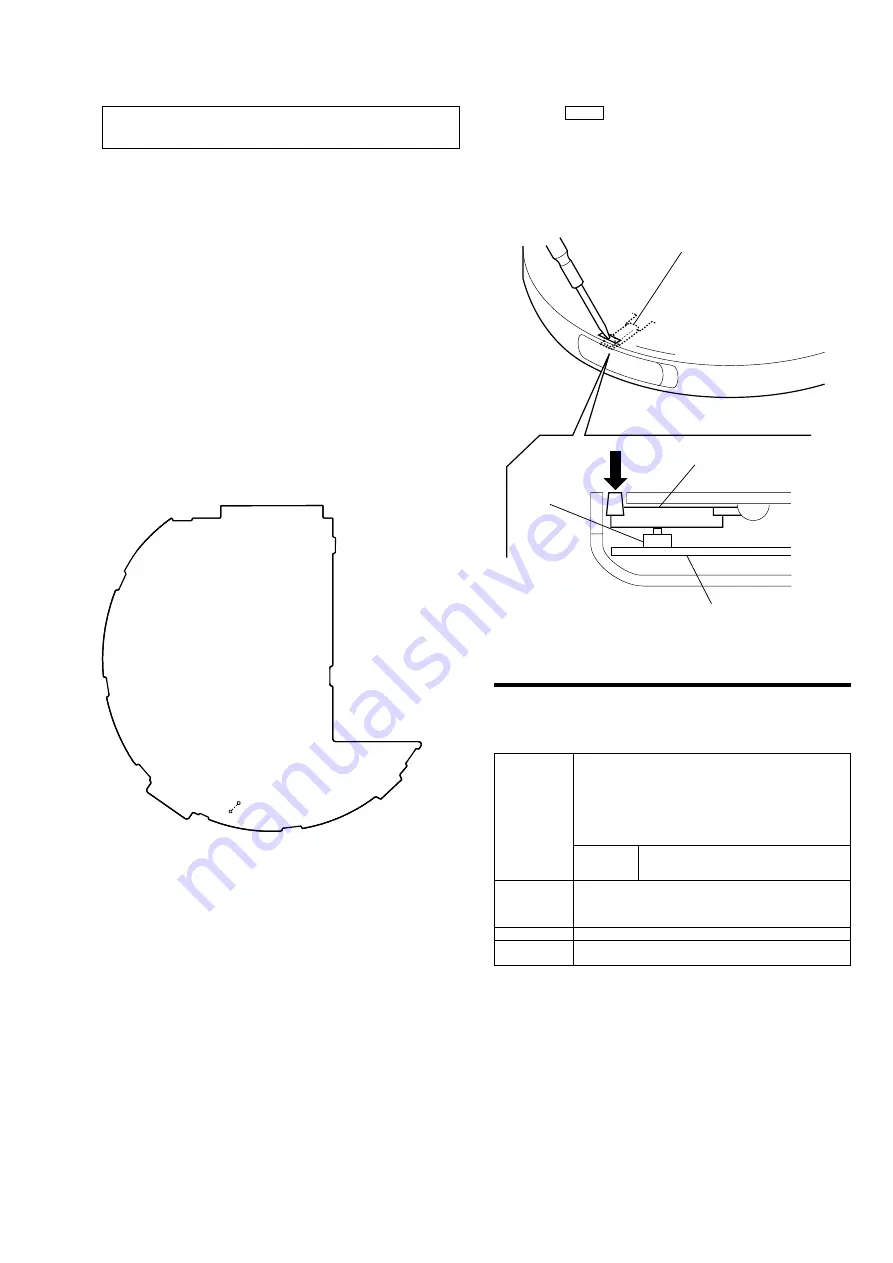
2. With a disc not set, turn on the S820 with a screwdriver having
a thin tip as shown in Fig.1.
NOTES ON HANDLING THE OPTICAL PICK-UP
BLOCK OR BASE UNIT
Fig. 1 Method to push the S820
S820
detection lever
detection lever
MAIN board
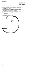
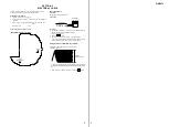
• In performing the repair with the power supplied to the set, re-
moving the MAIN board causes the set to be disabled.
In such a case, make a solder bridge to short SL825 (OPEN/
CLOSE DETECT) on the MAIN board in advance.
– MAIN Board (Component Side) –
SL825
(OPEN)

