background image

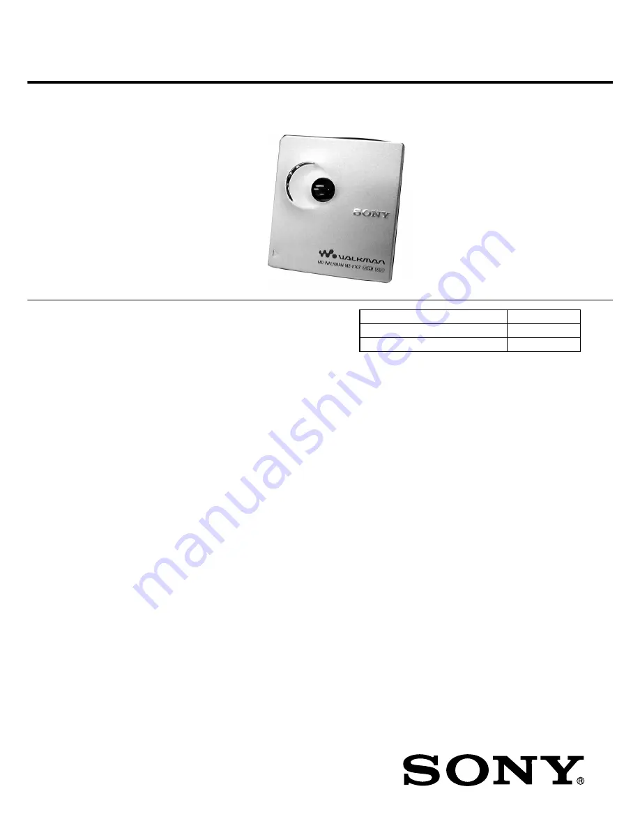
MZ-E707

SERVICE MANUAL

PORTABLE MINIDISC PLAYER

SPECIFICATIONS

E Model

Tourist Model

Model Name Using Similar Mechanism

MZ-E909

MD Mechanism Type

MT-MZE909-173

Optical Pick-up Mechanism Type

LCX-4E

US and foreign patents licensed from Dolby
Laboratories Licensing Corporation

Ver 1.1  2001.12

9-873-338-02

2001L0200-1

© 2001.12

Sony Corporation

Personal Audio Company

Published by Sony Engineering Corporation

Audio playing system

MiniDisc digital audio system

Laser diode properties

Material: GaAlAs
Wavelength: 

λ

 = 790 nm

Emission duration: continuous
Laser output: less than 44.6 

µ

W*

* This output is the value measured at a distance
   of 200 mm from the objective lens surface on
  the optical pick-up block with 7 mm aperture.

Revolutions

Approx. 300 rpm to 2,700 rpm

Error correction

ACIRC (Advanced Cross Interleave Reed Solomon Code)

Sampling frequency

44.1 kHz

Coding

ATRAC (Adaptive TRansform Acoustic Coding)
ATRAC3: LP2
ATRAC3: LP4

Modulation system

EFM (Eight to Fourteen Modulation)

Number of channels

2 stereo channels
1 monaural channel

Frequency response

20 to 20,000 Hz 

±

 3 dB

Wow and Flutter

Below measurable limits

Outputs

Headphones/earphones: stereo mini-jack,
maximum output level
5 mW + 5 mW load impedance 16 ohms

Power requirements

Nickel metal hydride rechargeable battery
One NH-14WM(A) (supplied): 1.2V, 1,350 mAh
One LR6 (size AA) battery (not supplied)
External power jack (for the battery charging
stand): Power rating 3V DC

Battery operation time

See “When to replace or recharge the battery”

Dimensions

Approx. 71.9 x 78.0 x 13.9 mm (w/h/d)
( 2 

7

 /

8

 x 3 

1

 / 

8

 x 

9

 /

16

 in.)

(not including projecting parts and controls)

Mass

Approx. 69 g (2.5 oz) (the player only)
Supplied accessories
Headphones/earphones with a remote control (1)
Battery charging stand (1)
AC power adaptor* (for the supplied battery
charging stand)
Rechargeable battery (1)
Rechargeable battery carrying case (1)
Dry battery case (1)
Carrying pouch (1)
AC plug adaptor (1) (world model only)

Design and specifications are subject to change without notice.

Summary of Contents for Walkman MZ-E707

Page 1: ...tic Coding ATRAC3 LP2 ATRAC3 LP4 Modulation system EFM Eight to Fourteen Modulation Number of channels 2 stereo channels 1 monaural channel Frequency response 20 to 20 000 Hz 3 dB Wow and Flutter Below measurable limits Outputs Headphones earphones stereo mini jack maximum output level 5 mW 5 mW load impedance 16 ohms Power requirements Nickel metal hydride rechargeable battery One NH 14WM A suppl...

Page 2: ...nent Notice that the minus side of a tantalum capacitor may be dam aged by heat TABLE OF CONTENTS Replacement of CXD2671B 206GA IC601 used in this set requires a special tool CAUTION Use of controls or adjustments or performance of procedures other than those specified herein may result in hazardous radiation exposure UNLEADED SOLDER Boards requiring use of unleaded solder are printed with the lea...

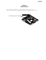
Page 3: ... repairing this device with the power on if you remove the main board this device stops working In this case you work without the device stopping by fastening the hook of the Open Close detection switch S809 Open Close detection switch S809 ...

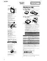
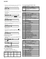
Page 4: ...f the track 6 Appears only with MDs that have been electronically labeled z The player can play the track recorded by 2 or 4 long playing mode LP2 or LP4 Normal stereo playback LP2 stereo playback LP4 stereo playback or monaural playback is automatically selected to match the audio source The display on the remote control will turn off shortly after you press x Do this Beeps2 in the headphones Tur...

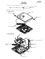
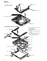
Page 5: ...emoved using the following procedure Upper lid ASSY Set Optical pick up ASSY Mechsnism ASSY Bracket R ASSY Main board Sub ASSY SW board 2 1 Screws M1 4 1 Screws M1 4 Bracket bottom ASSY Upper lid ASSY 7 5 2 4 9 Motor flexible board CN551 6 Claw 8 OP flexible board CN501 1 Move claw from bracket stop ASSY 3 Screw step Bracket stop ASSY Panel bottom Bracket R ASSY Mechanism deck ...

Page 6: ...ain board Bracket bottom ASSY SW board Panel bottom 7 Remove solder Two places 1 Screws M1 4 1 Screws M1 4 1 Screws M1 4 1 Screws M1 4 4 Lid battery case Case K battery Belt ornamental 3 Claw Audio board MAIN BOARD SUB ASSY Audio board is supplied with main board sub ASSY Audio board can not be moved away from main bord Give a damage when take it off forcibly The part that audio board overlap with...

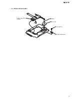
Page 7: ...7 MZ E707 3 5 OPTICAL PICK UP ASSY 5 3 Screw MI 1 4 4 Spring thrust detent 1 Washer 2 Gear SA Optical pick up ASSY LCX 4E ...

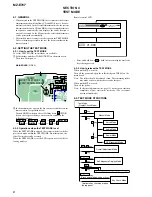
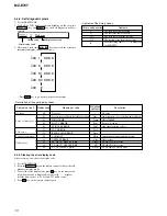
Page 8: ...ey means that on the remote control 4 2 SETTING THE TEST MODE 4 2 1 How to set the TEST MODE To set the TEST MODE two methods are available 1 Solder bridge and short TAP601 TEST on the main board Then turn on the power MAIN BOARD SIDE A 2 In the normal mode operate the keys on the set and those on the remote control as specified below Turn on HOLD switch on the set Holding down x STOP key on the s...

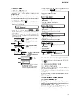
Page 9: ...hecks on the set s operation according to each individual function Usually no adjustments are made in this mode However the Manual mode is used to clear the memory before performing automatic adjustments in the OverallAdjustment mode 4 4 2 How to set the Manual mode 1 Set the TEST MODE and press key to set the Manual mode Remote control LCD display 4 During each test mode the display is changed fr...

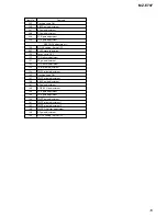
Page 10: ...ystem error 02 HIGH TEMP Temp HIGH TEMP 03 FOCUS ERROR Fcus Focus off center 04 SPINDLE ERROR Spdl Abnormal rotation of disc 11 TOC ERROR TOC TOC error 12 READ DATA ERROR Data Power system error 22 LOWBATT LBat Instantaneous interruption detected 31 OFFSET ERROR Ofst Offset error Offset error 32 FE_ABCD_OFFSET_ERR ABCD FE ABCD Offset error 33 TE_ABCD_OFFSET_ERR TE TE ABCD Offset error 34 X1_TE_OFF...

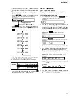
Page 11: ...LCD display 4 When all the key have been checked or when the top panel is opened during this checking the system terminates the Key Check mode and return to the TEST MODE 000 4 7 SOUND SKIP CHECK RESULT DISPLAY MODE This set can display and check the error count occurring during play Setting method of Sound Skip Check Result Display Mode 1 Setting the test mode 2 Press the N key activates the soun...

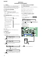
Page 12: ...de 4 963 646 01 MO disc PTDM 1 part code J 2501 054 A or commercially available MO disc recorded Digital voltmeter 5 2 2 Adjustment sequence The adjustments should be always performed in the following sequence 5 2 3 Power The power is supplied with 1 5 V DC from the battery case 5 3 RESET NV 5 3 1 How to reset NV 1 Set the TEST MODE 2 Set the Manual mode and set the item No 021 Reset NV LCD displa...

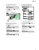
Page 13: ...ress key to set the Overall CD Adjustment mode Automatic adjustments are made LCD display XXX Item No for which an adjustment is being executed 764 VlPWM XX 000 Assy11 030 Ofst 030 OfstOK TEST MODE Display Check Mode Overall Adjustment Title Display ASSY CD overall Adjustment key VOLUME key key x MO overall Adjustment N key N key key x Electrical offset Adjustment key DISPLAY key key x key x Power...

Page 14: ...justment 312 Laser ON Focus UP VC correction ALFA offset adjustment 313 IJ offset adjustment 314 FE offset adjustment HPIT adjustment 320 Focus servo ON 324 TE offset adjustment 1 321 TE gain adjustment 328 TWPP gain adjustment 324 TE offset adjustment 1 332 TE offset adjustment 2 330 Tracking servo ON 336 ABCD gain adjustment 337 KF gain correction 338 RF gain adjustment 344 CD focus gain adjustm...

Page 15: ... 122 TON offset adjustment 121 TE gain adjustment 122 TON offset adjustment 123 TEIN offset adjustment 124 TWPP offset adjustment 130 Tracking servo ON 131 TWPP offset adjustment 136 ABCD gain adjustment 137 KF gain adjustment 139 ADIP BPF fo adjustment 144 FCS gain adjustment 145 TRK gain adjustment 134 TWPP gain adjustment 131 TWPP offset adjustment 1 132 TWPP offset adjustment 2 149 TWPP OP off...

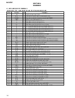
Page 16: ...ount monitor output terminal 21 ADFG O ADIP duplex FM signal 22 05 kHz 1 kHz output to IC601 22 DVDD Power supply terminal 2 4V digital system 23 SBUS I O Two way SSB serial data bus with the system controller IC601 24 SCK I SSB serial clock signal input from the system controller IC601 25 XRST I Reset signal input from the system controller IC601 L reset 26 OFTRK I Off track signal input from IC6...

Page 17: ...113 153 222 23 119 139 151 231 6 59 33 29 28 41 42 1 44 21 31 43 24 23 4 8 9 10 11 12 14 5 6 13 7 18 19 LASER AUTO POWER CONTROL Q501 3 4 2 19 11 20 13 12 5 18 9 10 14 15 16 17 7 8 6 1 TRACKING COIL FOCUS COIL 20 Jx Jy Jx Ix Iy Iy Ix Jx Jy A B C D PD Ix a F b c d MINIDISC OPTICAL PICK UP BLOCK LCX 4E LD AVCC S0 S1 AVCC S0 LD K LD A MON D C B A Jy Jx Ix Iy D D C PD I PD O C B A VREF VREF A C Jy Jx ...

Page 18: ... 1 1 5 5 10 10 15 15 20 20 22 44 40 35 30 25 23 CN501 OPTICAL PICK UP BLOCK LCX 4E X601 IC601 TP921 TP604 TP605 TP565 TP560 TP602 TP601 TP533 TP603 SHORT TEST MODE OPEN NORMAL MODE TAP601 FB801 FB802 IC801 1 1 5 15 2 10 19 20 4 8 5 RB553 RB554 D855 3 2 1 4 5 CN801 A AUDIO BOARD CN802 D201 D903 D101 M M902 SLED MOTOR M901 SPINDLE MOTOR 1 2 3 4 5 6 7 8 J301 2 1 5 8 CN551 11 11 1 682 471 C618 DRY BAT...

Page 19: ...563 TP609 TP610 TP607 TP558 TP606 TP552 TP556 TP561 TP564 TP608 TP557 TP551 TP104 TP204 TP810 TP811 TP812 TP813 TP302 TP203 TP103 TP570 TP572 TP573 TP571 TP526 TP952 TP525 TP532 TP524 TP530 TP523 TP527 TP528 TP529 TP521 TP501 TP502 TP591 TP516 TP919 TP907 TP902 TP920 TP912 TP911 TP904 TP519 TP517 TP513 TP514 TP515 TP510 TP511 TP512 TP507 TP508 TP509 TP577 TP576 TP557 TAP501 TP574 TP567 TP566 TP503...

Page 20: ... AVCC SO SI VCC EEPROM XBUSY RST GND XCS SK DI DO DIGITAL SIGNAL PROCESSOR DIGITAL SERVO SIGNAL PROCESSOR EFM ACIRC ENCODER DECODER SHOCK PROOF MEMORY CONTROLLER ATRAC ENCODER DECODER CSP Chip Size Package D A CONVERTER 16M BIT D RAM SYSTEM CONTROL MCUVDD0 MIFVSS3 XRST S MON VB MON CHG MON SET KEY 1 SET KEY 2 HIDC MON WK DET REC KEY AVDD AVSS VDIOSC OSCI OSCO HALF LOCK SW RMC KEY VSIOSC DAVDD VREF...

Page 21: ...ON U CLV CON W CLV CON V CLV CON U CLV PWM XRST MTR DRV FFCLR SLEEP FS4 VLON RMC DTCK RMC KEY VC PWN VL PWN SLD MON W SLD MON V SLD MON U SLD CON U SLD PWM SLD CON V SLD CON W TR1 TF1 FF1 FR1 FCS FCS TRK TRK FOCUS TRACKING COIL DRIVE SPINDLE SLED MOTOR DRIVE VLON XWK1 VSTB GND VL VLO VL L2 PGND2 PGND2 XWK2 XWK3 XWK4 VRMC VA VAFB VDFB VIFFB GND VC VCO VC L1 NC PGND1 PGND1 VCOUT DTC1 DTC2 RF2 INM2 P...

Page 22: ...C304 C306 C305 C103 C203 TAP801 OPEN CLOSE TP826 TP825 TP305 TP304 1 5 15 2 10 19 20 CN802 A MAIN BOARD CN801 1 6 7 12 13 18 19 IC301 24 1 5 9 CN803 1 9 CN804 11 1 682 470 SWITCH FLEXIBLE BOARD SW BOARD SIDE B SW BOARD SIDE A S808 HOLDc OFFtON S809 OPEN CLOSE R815 C860 R813 R814 R811 R812 11 11 1 682 473 11 11 1 682 473 S804 VOLUME S805 VOLUME S806 GROUP S801 x S803 S802 B D801 802 3 COLOR LED D80...

Page 23: ... 6 3V 6 8k 220k 0 01 OPEN CLOSE 20P OPEN CLOSE 6 8k 10k 15k 33k 33 10 6 3V 1 0 1 2SC4738FL 470p 9P 9P 68k TLQU1008 220 2 5V 220 2 5V MAZS068008SO MAZS068008SO 0 1 SET KEY XWK1 OPEN CLOSE HOLD SW GND XHP STB MUTE BEEP VIF UNREG R IN L OUT AGND AGND L IN R OUT STB MUTE BST SW BEEP GND VREF IN B OUT L PWR GND OUT R DET AGC IN BTS NF2 LPF2 NF1 LPF1 VREF OTUA BEEP IN L IN R VCC ICMT BEEP OTUB HOLD ON O...

Page 24: ...n face side Parts on the pattern face side seen from the Side B pattern face are indicated Parts face side Parts on the parts face side seen from the Side A parts face are indicated Main boards is four layer pritnted board However the patterns of layer 2 and 3 have not been included in this diagrams Replacement of IC601 used in this set requires a special tool Lead Layouts Lead layout of conventio...

Page 25: ...F 42 38 37 36 35 34 31 30 29 28 27 26 25 24 23 39 41 40 2 3 4 5 6 7 8 9 10 11 12 13 14 15 16 17 18 19 20 21 22 A B C D I J NPP TON CSL Aw Dw TON Peak TON Botm ADIP TE TEMP 33 32 S MONITOR TE RF FE APC ADIP T ON SERIAL I F PEAK BOTM ABCD Tpp Wpp V REF MT SW BST SW BEEP 19 20 21 22 23 24 18 17 16 15 14 13 PW SW 12 11 10 8 7 BST1 9 BST2 6 5 4 3 2 1 BST AGC PW B PW A ADD TC MT VCC INR INL BEEP OUTB BE...

Page 26: ...2 33 34 35 UO2 VMU2 VMR2 RO2 PGND2 FO2 VMF2 VI1 WI1 PGNDW1 WO1 WMVW1 VO1 PGNDUV1 UO1 VMU1 VMR1 RO1 PGND1 FO1 VMF1 19 18 17 16 15 FI1 RI1 COM1 CPUI1 CPVI1 22 21 20 CPWI1 GND2 NC BIAS VC ROE VC 3Phase control ch1 3Phase control ch2 3Phase Pre driver ch1 H BRIDGE PRE DRIVER CH1 H BRIDGE CONTROL CH1 VC VC VG VC VG VC VC OE VG VG VCVG VCVG GND VG VC VG VC VG VC VG VC VC VC U V W U V W H BRIDGE CONTROL ...

Page 27: ...SCUTCHEON 6 3 234 177 01 KNOB OPEN 7 3 234 178 02 BELT ORNAMENTAL SILVER 7 3 234 178 12 BELT ORNAMENTAL BLUE HK 7 3 234 178 22 BELT ORNAMENTAL ORANGE 7 3 234 178 32 BELT ORNAMENTAL GREEN HK 8 3 234 175 01 BUTTON CONTROL 9 3 234 176 01 WINDOW LED 10 3 227 923 21 CASE K BATTERY 11 1 682 470 11 PWB SWITCH FLEXIBLE 12 1 682 473 11 SWITCH BOARD 13 3 222 373 01 TERMINAL BOARD MINUS 14 3 234 179 01 LID B...

Page 28: ...EW M1 4 TAPPING 53 3 222 394 01 CHASSIS 54 3 224 779 01 SPRING THRUST DETENT 55 4 222 216 01 GEAR SA 56 3 338 645 31 WASHER 0 8 2 5 57 3 225 996 01 SCREW M1 4 EG PRECISION PAN 58 3 225 996 07 SCREW M1 4 EG PRECISION PAN 59 4 222 208 01 GEAR SB 60 3 043 237 02 BEARING N 61 4 222 203 01 SCREW LEAD 062 X 3379 869 1 OPTICAL PICK UP ASSY LCX 4E 63 3 222 391 01 SPRING M RACK 64 3 225 278 11 SCREW TAPPIN...

Page 29: ...RES CHIP 6 8K 5 1 16W R201 1 218 971 11 RES CHIP 33K 5 1 16W R202 1 218 971 11 RES CHIP 33K 5 1 16W R203 1 218 961 11 RES CHIP 4 7K 5 1 16W R204 1 208 635 11 RES CHIP 10 5 1 16W R206 1 218 963 11 RES CHIP 6 8K 5 1 16W R301 1 218 935 11 RES CHIP 33 5 1 16W R302 1 218 963 11 RES CHIP 6 8K 5 1 16W R303 1 218 981 11 RES CHIP 220K 5 1 16W X 3381 940 1 MAIN BOARD SUB ASSY including AUDIO BOARD 3 049 041...

Page 30: ...752 413 14 IC CXD2671 206GA IC801 8 759 680 85 IC AK6417AL L IC901 8 759 698 61 IC XPC18A32FCR2 JACK J301 1 793 288 62 JACK i INDUCTOR L503 1 469 570 21 INDUCTOR 10uH L901 1 419 258 21 INDUCTOR 68uH L902 1 419 646 21 INDUCTOR 47uH L904 1 414 398 11 INDUCTOR 10uH L905 1 412 032 11 INDUCTOR CHIP 100uH TRANSISTOR Q501 8 729 922 10 TRANSISTOR 2SA1577 QR Q801 8 729 429 44 TRANSISTOR XP1501 Q803 8 729 0...

Page 31: ... manual The components identified by mark 0 or dotted line with mark 0 are critical for safety Replace only with part number specified 501 506 502 505 504 507 503 508 zDry Battery Case z Rechargeable Battery z Carrying Pouch z Battery Charging stand z Headphnes earphones with a remote control z AC adaptor MISCELLANEOUS 11 1 682 470 11 SWITCH FLEXIBLE BOARD 062 X 3379 869 1 OPTICAL PICK UP ASSY LCX...

Page 32: ...ump to the revised page Also clicking the version at the upper right on the revised page allows you to jump to the next revised page Ver Date Description of Revision 1 1 2001 12 Change the main board to service ASSY including audio board SPM 01053 1 0 2001 10 New ...

Reviews: