25
NW-A605/A607/A608
• IC Pin Function Description
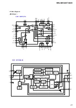
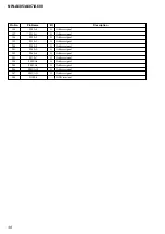
MAIN BOARD IC2001 TEA5767HN (RECEIVER)
Pin No.
Pin Name
I/O
Description
1
NC
—
Not used
2
CPOUT
O
Charge pump output of the synthesiser PLL
3
VCOTANK1
O
VCO tuned circuit output 1
4
VCATANTK2
O
VCO tuned circuit output 2
5
VCC (VCO)
—
VCO supply voltage
6
DGND
—
Ground terminal
7
VCCD
—
Digital supply voltage
8
DATA
I/O
Bus data line input/output
9
CLOCK
I
Bus clock line input
10
NC
—
Not used
11
WRITE/READ
O
Write/read control for the 3-Wire bus
12
BUSMODE
I
Bus mode select input (Fixed at “H”)
13
BUSENABLE
I
Bus enable input
14
SWPORT1
—
Software programmable port 1 (Not used)
15
SWPORT2
—
Software programmable port 2 (Not used)
16
XTAL1
—
Crystal oscillator input 1 (Not used)
17
XTAL2
I
Crystal oscillator input 2 (32 kHz)
18
PHASEFIL
—
Phase detector loop filter
19
PILFIL
—
Pilot detector lowpass filter
20
NC
—
Not used
21
NC
—
Not used
22
VAFL
O
Audio left output
23
VAFR
O
Audio right output
24
TMUTE
—
Time constant for the softmute
25
MPXOUT
—
FM demodulator MPX out (Not used)
26
VREF
—
Reference voltage
27
TIFC
—
Time constant for IF centre adjust
28
LIMDEC1
—
Decoupling IF limiter 1
29
LIMDEC2
—
Decoupling IF limiter 2
30
NC
—
Not used
31
NC
—
Not used
32
IGAIN
—
Gain control current for IF filter
33
AGND
—
Ground terminal
34
VCCA
—
Analog supply voltage
35
RFI1
—
RF input 1
36
RFGND
—
Ground terminal
37
RFI2
—
RF input 2
38
TAGC
I
Time constant RF AGC
39
LOOPSW
O
Switch output of synthesiser PLL filter
40
NC
—
Not used


