background image

4

NW-E8P

8

Transferring songs from the computer to
Network Walkman (Check-out)

In order to check out digital audio files from your computer, first you must install the supplied
OpenMG Jukebox software and then import digital audio files to OpenMG Jukebox.
For details, refer to the OpenMG Jukebox operating Instructions.

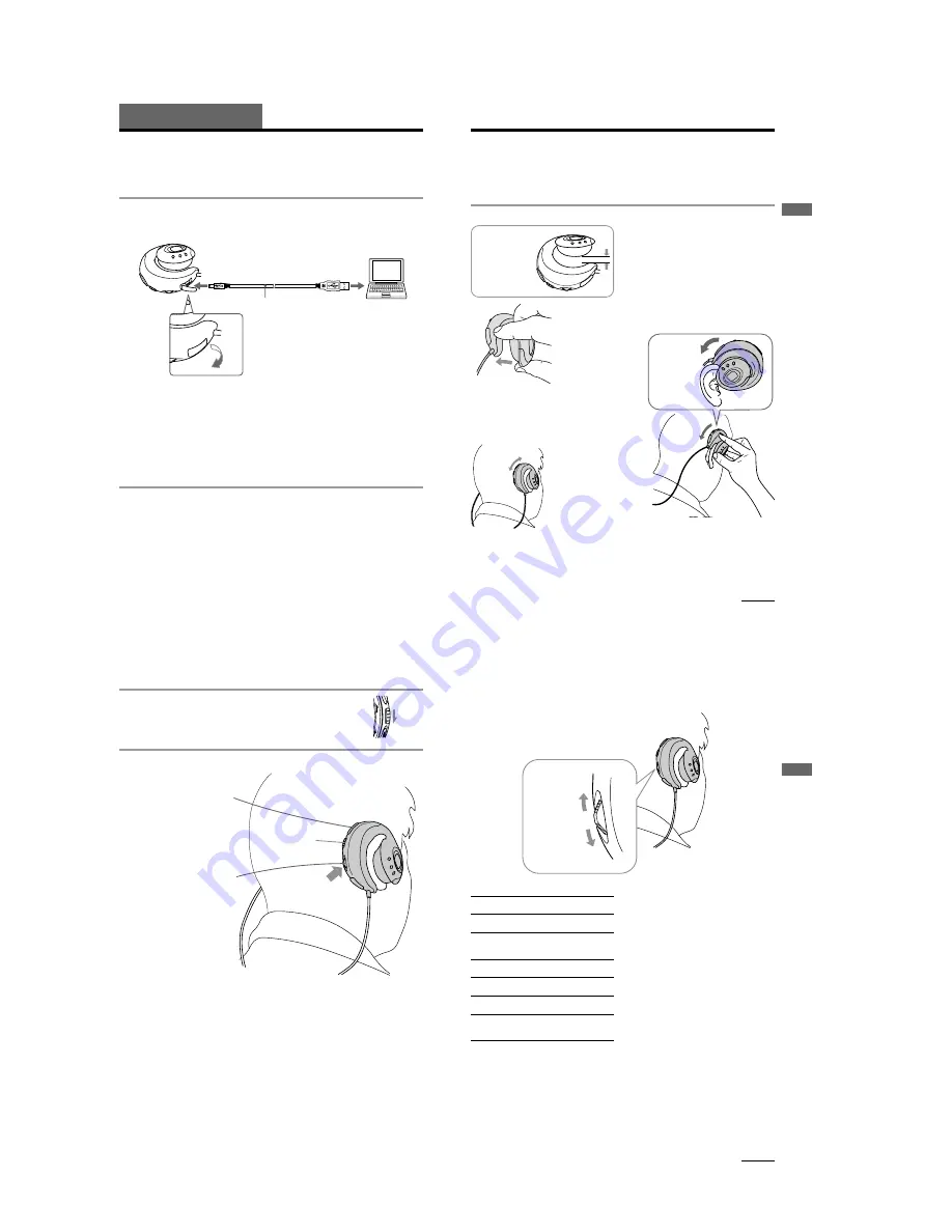
1

Connect Network Walkman to your computer

Connect the narrow connector of the supplied dedicated USB cable into the dedicated USB jack on
Network Walkman, then the wide connector to the USB jack of your computer.
“CONNECT” appears in the display.

Notes

• Do not connect more than two USB devices (player) to your computer. Normal operation will not be

guaranteed.

• If you use this player with a USB hub or a USB extension cable normal operation is not guaranteed.
• A malfunction may occur depending on the USB devices connected at any one time.
• Be sure to insert a fresh Alkaline battery into the unit. If the battery is not inserted, or battery power is

exhausted, the unit will not be identified by the computer.

• When connecting Network Walkman to your computer for the first time, the USB driver Installer window

appears. Please follow the instructions in the Installer window.

• Connect Network Walkman only as necessary. Disconnect the dedicated USB cable when not needed.

2

Transfer the music file to Network Walkman (Check-out)

For details on how to operate, refer to the OpenMG Jukebox Operating Instructions.

Tip

To transfer the song back to the computer (check-in), refer to the OpenMG Jukebox software instruction manual
or the online help.

Basic Operations

Dedicated USB cable (supplied)

to the USB jack

to the dedicated
USB jack

9

Basic Operations

Listening to music with Network
Walkman

Please insert the battery before use (see page 7).

Note

When using Network Walkman, be sure to disconnect it from the computer.

   Putting the player on your ears

continued

Notes

• Please remove earrings.
• If you wear the glasses, remove your glasses before

putting on this player and put them on again.

• Be sure not to open the attaching part more than

2 cm. Otherwise, this player may deform and
might not sit on your ears comfortably. Note that
if you press the player to opposite side, it also
may deform.

1

Pinch the center of
the player with your
thumb and middle
finger, and then open
the attaching part
with your forefinger.

2

Hook the cured part
around the back of your
ear and twist it to the
earlobe direction to sit it
on your ear. If your hair
hangs over your ear,
please push back your
hair before attaching it.

3

Adjust the position of
the player to fix it
comfortably.

If you cannot attach the player to your ear comfortably

Confirm the position of the player with a mirror. In the correct position, your ears should appear as
illustrated. if your ears are small and not visible as shown, use the supplied attachments (see page 15).

To remove the player from your ears

Twist the player to the opposite direction when attaching it, and remove it.

The attaching
part of this player
would be open
(be apart)
flexibly.

Hook the
edge of the
attaching part
to the back of
your ear and
twist it.

k

k

2cm

10

Listening to music with Network Walkman (continued)

2

    Release the HOLD function

If the HOLD switch is in the arrow direction ( the yellow mark is
visible), slide it to the opposite direction to release the HOLD function.

3

    Start playback

If playback does not start

Make sure the HOLD function is released.

To stop playback

Press the Jog lever 

Bx

.

Tip

If you do not operate the player for 3 seconds while in stop mode, the display automatically turns off.

1

Press the Jog lever

Bx

. Playback starts.

When playback ends,
the playback
automatically stops
(in the case the player
is set to REPEAT OFF).

2

 VOLUME

+/– button to adjust
the volume.

HOLD switch

H

O

L

D

FF

11

Basic Operations

On other operations

To

Go to the beginning
of the next track

Go to the beginning
of succeeding
tracks 

1)

Go to the beginning
of the current track

Go to previous
tracks  

1)

Go forward 

2)

Go backward 

2)

Operation of
the Jog lever

Press in the FF direction
once.

Press in the FF direction
repeatedly.

Press in the REW direction
once.

Press in the REW direction
repeatedly.

During playback, press in
the FF direction and hold .

During playback, press in
the REW direction and
hold.

FF direction

Jog lever

REW direction

1)

While in stop mode, press the Jog lever in the FF
direction and hold, you can go to the beginning of
the next track and succeeding tracks continuously.
While in stop mode press the Jog lever in the REW
direction and hold, you can go to the beginning of
the current track and previous tracks continuously.

2)

If you press and hold in the FF or REW direction
for more than 5 seconds, the search speed
increases.

continued

Summary of Contents for Walkman NW-E8P

Page 1: ... 95 F Power source LR03 Size AAA alkaline battery Battery life Approx 7 hours Mass approx 90g 3 2 oz battery included Memory capacity 64MB including the system software 60 6MB available Supplied accessories LR03 Size AAA alkaline battery 1 Attachments 1 for left 1 for right Dedicated USB cable 1 Carrying pouch 1 CD ROM OpenMG Jukebox installation disc 1 NW E8P Operating Instructions 1 OpenMG Jukeb...

Page 2: ...aged by heat TABLE OF CONTENTS Replacement of CXD9644GG IC710 used in the set requires a special tool z UNLEADED SOLDER Boards requiring use of unleaded solder are printed with the lead free mark LF indicating the solder contains no lead Caution Some printed circuit boards may not come printed with the lead free mark due to their particular size LEAD FREE MARK Unleaded solder has the following cha...

Page 3: ...y 1 AVLS indication 2 MEGA BASS indication 3 Battery remain indication 4 Play mode indication 5 Text graphic information display 1 DISPLAY button 2 VOLUME button 3 HOLD switch 4 Jog lever 5 Dedicated USB jack 6 Display 7 MEGA BASS AVLS button 8 P MODE button 9 Ear pad 0 Battery compartment 1 2 3 4 5 6 7 8 rear of the left player 9 0 1 2 3 4 5 ...

Page 4: ...humb and middle finger and then open the attaching part with your forefinger 2 Hook the cured part around the back of your ear and twist it to the earlobe direction to sit it on your ear If your hair hangs over your ear please push back your hair before attaching it 3 Adjust the position of the player to fix it comfortably If you cannot attach the player to your ear comfortably Confirm the positio...

Page 5: ...etwork Walkman continued On the display 1 AVLS indication page 13 The indication lights up while the AVLS function is activated 2 MEGA BASS indication page 13 The indication lights up while the MEGA BASS function is activated 3 Battery remain indication page 7 The remaining battery power is displayed 4 Play mode indication page 14 The selected play mode is displayed 5 Play status Track number disp...

Page 6: ...SY Arm lid R 4 Remove solder 2 places 2 Turn to clockwise to release lock Red Black Black 7 Screw B1 7x5 5 Screws B1 7x5 7 Screw B1 7x5 Front plate Red Ear pad Driver ASSY SP2 Driver ASSY Marking red Red Glue Black Connection of driver ASSY Arm lid R rear side Installation of holder lid R and arm lid R Claw Holder lid R rear side Holder lid R 5 3 1 Holder R ASSY 2 LCD flexible board Power board CN...

Page 7: ...4 core Wiring of cord 4 core Arm lid L Front plate 2 Turn to clockwise to release lock 5 Screws B1 7x5 8 Screw B1 7x5 8 Screws B1 7x5 7 Open the battery lid Driver ASSY SP1 Holder lid L Holder L ASSY MDD flexible board 4 Remove solder 2 places Note When soldering paying attention as holder L doesn t transform it by a heat Installation of holder lid L and arm lid L Claw Holder lid L Lid L arm rear ...

Page 8: ...st mode Open Normal mode 1 4 regulated DC power supply Connecting cable supplied with the set USB Connector 1 784 009 11 or 1 779 676 11 Set Battery terminal CN701 USB Connector regulated DC power supply LCD Check Ver destination display All display lit All display off Flash memory bad block check Bx Bx Destination setting Contrast adjustment Low voltage check Bx Bx High DC detection check Low DC ...

Page 9: ...f CSP chip size package cannot be measured because its lead layout is different form that of conventional IC Replacement of IC710 used in the set requires a spe cial tool 2 VOLT DIV 1 V AC TIME DIV 20 µsec VOLT DIV 1 V AC TIME DIV 20 µsec 3 Q902 D IC901 5 EXT VOLT DIV 1 V AC TIME DIV 5 µsec 4 Q903 D 1Vp p 22 5792MHz 2 8Vp p 3Vp p 2 2Vp p 10 µsec IC701 zb XTO MAIN SECTION POWER SECTION LCD check Ch...

Page 10: ...1 A6 D0 DACK DREQ XRST XCS XWR XRD XINT D15 D12 XTRST TRON VBUS D D USB DEVICE CONTROLLER VOUT VIN POWER SWITCH USB CE I O0 I O7 I O8 I O15 1D 1Q 6Q 6D 25 32 41 48 3 4 7 8 13 14 2 5 6 9 12 15 17 22 40 37 34 23 163 170 173 180 3 4 4 4 1 4 BUS DRIVER CLK 8 9 10 11 12 13 1 2 3 USB B FRIO 0 15 FRIO 1 6 FRIO 0 15 VDD CORE CONTROL SYSTEM CN701 USB CONNECTOR USB D USB D VBUS FRRST USB INT USB DREQ USB XD...

Page 11: ...712 C701 JC722 X701 TP702 TP3 TP701 TP703 TEST C729 C739 C738 IC820 CN701 USB CONNECTOR IC752 IC710 4 4 1 1 1 2 2 3 3 5 5 5 1 5 14 10 8 7 IC852 1 5 15 20 11 10 IC853 IC8514 1 2 3 5 D784 D783 CN702 C616 C807 T701 IC761 IC810 4 1 2 3 1 5 10 15 24 20 48 45 40 35 30 25 IC751 13 13 1 681 242 13 13 1 681 242 MAIN BOARD SIDE B MAIN BOARD SIDE A FB702 FB704 P 7 0 1 D 7 8 1 FB703 1 1 2 10 10 C809 10 12 13 ...

Page 12: ...RST NC NC NC NC I O15 I O14 I O13 I O12 I O11 I O10 I O9 I O8 NC NC VCC VCC VSS VSS NC NC I O7 I O6 I O5 I O4 I O3 I O2 I O1 I O0 NC XSE NC NC NC NC R XB XRE XCE NC NC VCC VSS NC NC CLE ALE XWE XWP XEX RST NC NC NC NC I O15 I O14 I O13 I O12 I O11 I O10 I O9 I O8 NC NC VCC VCC VSS VSS NC NC I O7 I O6 I O5 I O4 I O3 I O2 I O1 I O0 FLASH RAM IC751 FLASH RAM D6 D5 D4 D3 D2 D1 D0 VDDIO1 VSSIO1 A18 A17...

Page 13: ...R IO2 FR IO3 FR IO4 FR IO5 FR IO6 FR IO7 FR IO8 FR IO9 FR IO10 FR IO11 FR IO12 FR IO13 FR IO14 FR IO15 USB INT USB DREQ USB XRST USB XDACK FR IO1 FR IO2 FR IO3 FR IO4 FR IO6 FR IO5 VCC GND 1A 1B 1Y 2A 2B 2Y 4A 4B 4Y 3A 3B 3Y GND 4Q 4D 3D 3Q 2Q 2D 1D 1Q XOE CLK 5Q 5D 6D 6Q 7Q 7D 8D 8Q VCC IC853 IC852 SN74LVC32APWR SN74LVC374APWR D2 D3 D4 D5 D6 D7 D8 D9 D10 D11 GND VCC XOUT XIN GND VCC A1 A2 A3 A4 A...

Page 14: ... G Q906 IC902 IC903 1 5 16 9 1 6 7 12 13 18 19 24 8 IC301 IC302 S704 HOLD S702 VOLUME S701 VOLUME S706 DISPLAY S705 P MODE S707 MEGEBASS AVLS ON OFF POWER BOARD SIDE B POWER BOARD SIDE A 12 12 1 681 243 1 681 246 11 1 681 245 11 12 12 1 681 243 LCD FLEXIBLE BOARD LCD UNIT SP1 SPEAKER L CH RED GREEN GREEN CLEAR RED CLEAR SP2 SPEAKER R CH A MAIN BOARD CN702 DRY BATTERY SIZE AAA IEC DESIGNATION LR03 ...

Page 15: ...0k 1M 220 2 5V 0 01 10k 47 6 3V 1M 1M 1M MA2Z748 1000p 1000p 1 2SC4738F 0 1 1000p D916 MA2S728 S12302DS 10 6 3V XP152A12COMR XP152A12COMR 1M 100 6 3V 6 8k 10 6 3V MA2Z748 WAKE0 WAKE0 WAKE1 WAKE1 ACTRO ACTRO TSB TSB ELON ELON FS256 PCMO BCK LRCK DEMP XPDDAC H P POWER MUTE BEEP GIOAI XHOLD WAKE0 WAKE1 ACTRO TSB LCD VDD DCDT WAKE USB RESET D GND D GND D GND D GND XRST EXB MONI VDDIO2 VDDIO1 DC IN VDD...

Page 16: ... 6D C6 C5 5D V REF MT SW BST SW BEEP 19 20 21 22 23 24 18 17 16 15 14 13 PW SW 12 11 10 8 7 BST1 9 BST2 6 5 4 3 2 1 BST AGC PW B PW A ADD TC MT VCC1 INB INA BEEP OUTB BEEP OUTA VCC2 OUTA PWR GND OUTB DET AGC IN BST OUT BST NF2 LPF2 BST NF1 LPF1 VREF VREF IN GND BEEP IN BST SW MUTE PWSW R B HIGH VOLTAGE GENERATOR ADDRESS REGISTER COLUMN BUFFER COLUMN DECORDER DATA REGISTER SENSE AMPLIFIER MEMORY CE...

Page 17: ...ption Remark Ref No Part No Description Remark 6 1 L CH SECTION 1 3 228 499 01 LID L HOLDER 2 3 228 509 01 LID BATTERY CASE 3 3 228 510 01 KNOB BATTERY CASE LID 4 2 647 241 11 SCREW B1 7X5 5 3 228 516 01 TERMINAL BATTERY 6 3 229 875 01 SPRING BATTERY CASE LID 7 3 228 515 01 TERMINAL BATTERY 8 1 757 760 11 CORD 4 CORE 9 3 228 517 01 BUSHING 10 1 681 245 11 MDD FLEXIBLE BOARD 11 3 228 501 01 LID L A...

Page 18: ...D SUB ASSY 58 3 331 685 01 SPACER OPEN KNOB 59 A 3021 416 A POWER PC BOARD ASSY 60 3 228 519 01 LID USB 61 3 228 517 01 BUSHING 62 X 3380 945 1 HOLDER R ASSY 63 3 228 514 01 BUTTON FUNCTION 64 3 228 502 01 LID R ARM 65 1 476 626 11 LCD UNIT 66 1 681 246 11 LCD FLEXIBLE BOARD 67 3 228 508 01 PLATE FRONT SP2 X 3380 946 1 DRIVER ASSY R CH 63 62 61 59 58 57 54 67 66 64 65 52 52 52 53 51 55 56 60 SP2 n...

Page 19: ...0 11 CERAMIC CHIP 0 1uF 16V C733 1 107 820 11 CERAMIC CHIP 0 1uF 16V C734 1 107 820 11 CERAMIC CHIP 0 1uF 16V C735 1 107 820 11 CERAMIC CHIP 0 1uF 16V C736 1 107 820 11 CERAMIC CHIP 0 1uF 16V C737 1 107 820 11 CERAMIC CHIP 0 1uF 16V C738 1 107 820 11 CERAMIC CHIP 0 1uF 16V C739 1 107 820 11 CERAMIC CHIP 0 1uF 16V C740 1 107 820 11 CERAMIC CHIP 0 1uF 16V C741 1 107 820 11 CERAMIC CHIP 0 1uF 16V C75...

Page 20: ...R CRYSTAL 22 5792MHz X801 1 781 651 21 VIBRATOR CRYSTAL 12MHz A 3021 416 A POWER BOARD COMPLETE CAPACITOR C101 1 128 934 11 CERAMIC CHIP 0 33uF 20 10V C102 1 135 868 91 TANTAL CHIP 220uF 20 2 5V C103 1 165 128 11 CERAMIC CHIP 0 22uF 16V C104 1 164 937 11 CERAMIC CHIP 0 001uF 10 50V C201 1 128 934 11 CERAMIC CHIP 0 33uF 20 10V C202 1 135 868 91 TANTAL CHIP 220uF 20 2 5V C203 1 165 128 11 CERAMIC CH...

Page 21: ... 15K 5 1 16W R103 1 208 635 11 RES CHIP 10 5 1 16W R104 1 218 961 11 RES CHIP 4 7K 5 1 16W R105 1 218 961 11 RES CHIP 4 7K 5 1 16W R201 1 218 963 11 RES CHIP 6 8K 5 1 16W R202 1 218 967 11 RES CHIP 15K 5 1 16W R203 1 208 635 11 RES CHIP 10 5 1 16W R204 1 218 961 11 RES CHIP 4 7K 5 1 16W R205 1 218 961 11 RES CHIP 4 7K 5 1 16W R301 1 218 963 11 RES CHIP 6 8K 5 1 16W R302 1 218 931 11 RES CHIP 15 5 ...

Page 22: ... LCD UNIT 66 1 681 246 11 LCD FLEXIBLE BOARD SP1 X 3380 946 1 DRIVER ASSY L CH SP2 X 3380 946 1 DRIVER ASSY R CH ACCESSORIES 501 1 757 759 11 CORD CONNECTION USB 5P 502 3 231 263 01 ATTACHMENT L 503 3 231 264 01 ATTACHMENT R 3 231 827 01 POUCH CARRYING 3 237 113 21 APPLICATION SOFT CD ROM AEP 3 237 113 31 APPLICATION SOFT CD ROM E 3 237 114 11 MANUAL INSTRUCTION ENGLISH 3 237 114 31 MANUAL INSTRUC...

Page 23: ...23 NW E8P ...

Page 24: ...jump to the revised page Also clicking the version at the upper right on the revised page allows you to jump to the next revised page Ver Date Description of Revision 1 0 2001 10 New 1 1 2002 10 Change the MAIN PC BOARD ASSY to the MAIN BOARD SUB ASSY SPM 02043 ...

Reviews: