background image

— 2 —

SECTION  1

GENERAL

Getting Started

Installing the Battery

(See Fig. 

B

)

1

While pressing the battery
compartment lid, slide it to open.

2

Insert one size AAA (R03) battery (not
supplied) with correct polarity.

3

To close the lid, press and slide the lid
down until it clicks.

When to replace the battery

Replace the battery when the sound becomes
weak or distorted. Remove the old battery and
insert a new one.

Battery life (approximate hours)

Sony

Sony

alkaline

size AAA

size AAA

(R03)

(LR03)

FM reception

  80

40

AM reception

100

50

Notes on the battery

• Align the battery correctly.
• The dry battery cannot be charged.
• To avoid damage from possible battery

leakage, remove the battery when unit will
not be used for a long time.

Wearing the Radio

1

Pull out the support band fully from
the headband.

2

Adjust the headband and the support
band to fit your head.

Note on the support band

(See Fig. 

A

)

When the radio not in use, put the support band
back by pushing down both ends as illustrated
and push it back underneath the headband.

Note on the light reflector
(See Fig. 

A

)

This reflector reflects a car light at night for your
safety.

Playing the Radio

1

Set 

POWER

 to 

ON

.

2

Set 

BAND

 to select 

FM

 or 

AM

.

For FM, set 

SENS

 to 

LOCAL

 if interference is

prevalent and reception is too strong. Under
normal condition, set it to 

DX

.

3

Turn 

TUNE

 (tuning) to tune in a station.

4

Adjust the volume using 

VOL

.

To turn off the radio

Set 

POWER

 to 

OFF

.

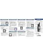
AAA (R03) x 1

Head band

Light reflector

FM flexible
antenna

BAND

SENS

VOL

 Driver
 units

POWER

 Support band

Insert the 

#

 side of the

battery first.

Battery
compartment

Dial scale

A

TUNE

B

This section is extracted from
instruction manual.

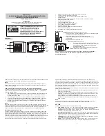
1.

Check the area of your repair for unsoldered or poorly-soldered
connections.  Check the entire board surface for solder splashes
and bridges.

2.

Check the interboard wiring to ensure that no wires are
"pinched" or contact high-wattage resistors.

3.

Look for unauthorized replacement parts, particularly
transistors, that were installed during a previous repair.  Point
them out to the customer and recommend their replacement.

4.

Look for parts which, through functioning, show obvious signs
of deterioration.  Point them out to the customer and
recommend their replacement.

5.

Check the B+ voltage to see it is at the values specified.

6.

Flexible Circuit Board Repairing

• Keep the temperature of the soldering iron around 270˚C

during repairing.

• Do not touch the soldering iron on the same conductor of the

circuit board (within 3 times).

• Be careful not to apply force on the conductor when soldering

or unsoldering.

SAFETY CHECK-OUT

After correcting the original service problem, perform the following

safety checks before releasing the set to the customer.

Summary of Contents for Walkman SRF-H3

Page 1: ...ncy range FM 87 6 108 MHz AM 530 1 710 kHz Power output 5 0 mW 5 0 mW at 10 harmonic distortion Headphone type Dynamic Power requirements 1 5 V DC one size AAA R03 battery Mass Approx 132 g 4 7 oz incl a battery Design and specifications are subject to change without notice Ver 1 0 2000 07 ...

Page 2: ...eception is too strong Under normal condition set it to DX 3 Turn TUNE tuning to tune in a station 4 Adjust the volume using VOL To turn off the radio Set POWER to OFF AAA R03 x 1 Head band Light reflector FM flexible antenna BAND SENS VOL Driver units POWER Support band Insert the side of the battery first Battery compartment Dial scale A TUNE B This section is extracted from instruction manual 1...

Page 3: ... 2 Push this portion down Cabinet rear R assy 1 Unsolder two lead wires Model name SRF H3 Gear tuning 1 Turn CV1 fully in the direction of arrow Cabinet rear R assy CV1 2 2 1 CABINET FRONT R ASSY 2 2 HOLDER WITH DRIVER 2 3 GEAR TUNING INSTALLATION Note Follow the disassembly procedure in the numerical order given ...

Page 4: ... trimmer capacitors FM IF ADJUSTMENT Adjust for a maximum reading on level meter T2 10 7 MHz FM FREQUENCY COVERAGE ADJUSTMENT Adjust for a maximum reading on level meter L4 87 35 MHz CT1 3 108 05 MHz FM TRACKING ADJUSTMENT Adjust for a maximum reading on level meter L3 87 35 MHz CT1 2 108 05 MHz FM Setting BAND switch FM AM Setting BAND switch AM signal AM RF signal generator 30 amplitude modulati...

Page 5: ...BPF FM RF IN FM RF IN AM IF IN FM RF OUT 1 FM OSC 3 AM OSC 4 L2 FERRITE ROD ANTTENA L5 BUFFER Q1 CT1 1 CV1 1 CV1 TUNE 13 5 14 AM RF IN AM MIX OUT FM MIX OUT FM MIX AM MIX AM OSC FM OSC CF1 12 T1 CF2 7 8 5 13 16 15 2 AM AGC FM DET VCO R CH R CH RV2 38k 19k 90º 19k 0º AM DET AF OUT VCC1 R OUT L OUT 9 RV1 VCO L3 CT1 2 B R16 B R16 B R16 B R16 CV1 2 FM AM FRONT END IC1 1 3 STEREO MPX IC2 SP1 SPEAKER SP...

Page 6: ...SRF H3 7 8 4 2 SCHEMATIC DIAGRAM 16 ...

Page 7: ...SRF H3 9 10 4 3 PRINTED WIRING BOARD Ref No Location D1 F 3 IC1 E 9 IC2 E 3 IC3 C 2 Q1 D 10 Semiconductor Location ...

Page 8: ... CAP VARIABLE IC IC1 8 759 230 65 IC TA7792F COIL L1 1 414 142 61 INDUCTOR 1uH L2 1 402 505 11 ANTENNA FERRITE ROD MW L3 1 428 123 11 COIL AIR CORE L4 1 428 122 11 COIL AIR CORE L5 1 406 390 21 COIL OSC AUDIO TUNER Ref No Part No Description Remarks Ref No Part No Description Remarks SECTION 6 ELECTRICAL PARTS LIST NOTE Due to standardization replacements in the parts list may be different from th...

Page 9: ... 10K 5 1 10W R15 1 216 295 00 SHORT 0 R16 1 216 009 00 RES CHIP 22 5 1 10W R17 1 216 061 00 METAL CHIP 3 3K 5 1 10W R18 1 216 049 11 RES CHIP 1K 5 1 10W R19 1 216 025 11 RES CHIP 100 5 1 10W R21 1 216 049 11 RES CHIP 1K 5 1 10W SWITCH S1 1 554 667 00 SWITCH SLIDE SENS S2 1 553 510 11 SWITCH SLIDE BAND TRANSFORMER T1 1 404 920 21 TRANSFORMER IF T2 1 404 921 21 TRANSFORMER DISCRIMINATOR MISCELLANEOU...

Page 10: ...SRF H3 14 Sony Corporation Audio Entertainment Group 2000G16024 1 Printed in Japan 2000 7 Published by PE General Engineering Dept 9 927 940 31 ...

Reviews: