background image


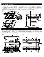
The wall plates must be secured to wall studs capable of supporting at least four (4) times the weight of the unit. To determine the center viewing height of the plasma 
display. Temporarily position the rod of the lower wall plate to the bottom hook of the secured mounting brackets and determine and note the distance between the bottom 
of the plasma display to the bottom of the wall plate (See Fig 3 and 4). Measure the distance from the floor to where the bottom of the plasma will be (Example 60"). Add 
the noted distance to the 60" and mark you first securing points (Example 60"+4"=64"). Level and secure the bottom plate with four (4) 5/16" lag bolts and washers 
(supplied). See Fig 4. 

Note: 

The wall plate provides you with three (3) 16" stud center patterns and one (1) 24" stud center pattern to assist you in your installation.


2. FASTEN LOWER PLATE TO WALL 

3. SECURE UPPER WALL PLATE  

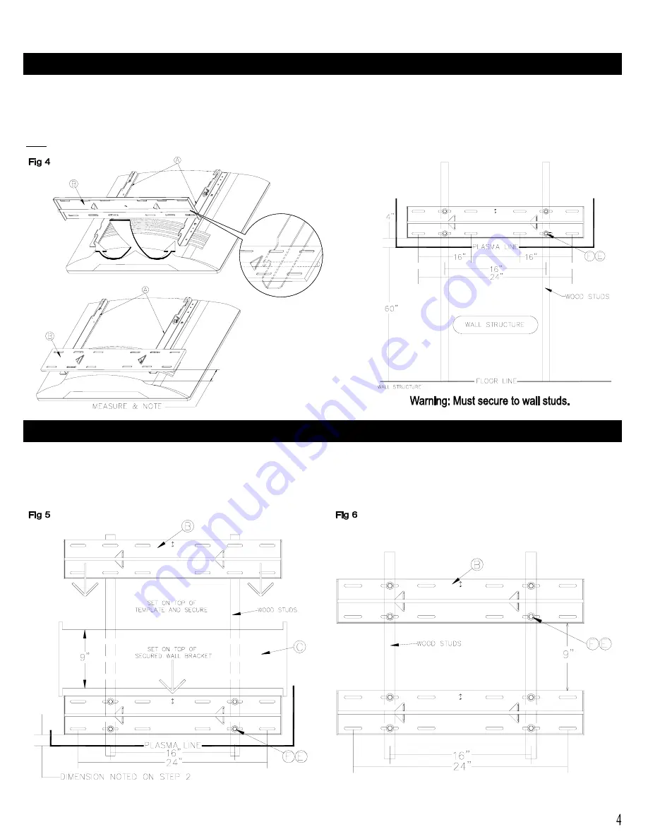
With the lower wall plate secured to the wall structure, place the (supplied) cardboard template over the top outside edges of the lower plate. Place the bottom and outside 
edges of the upper wall plate into the top portion of the template and mark the second set of securing points for the upper wall plate, see Fig 5. Secure the upper wall plate 
with the four (4) 5/16" lag bolts and flat washers (supplied). The wall plate must be secured to wall studs capable of supporting at least four (4) times the weight of the unit. 
The distance between the two plates should end up at 9". See Fig 6. 


Summary of Contents for WB-PW1

Page 1: ... Left and right mounting arms for the KZ 32 KZ 42 plasma displays 1pc left 1pc right Note Mounting points for the plasmas differ Please see diagram for mounting point specifications B Mount wall brackets 2 pc C Cardboard template for 9 accurate separation of the wall brackets 1pc Consult authorized service personnel for the installation of this unit Instructions must be followed precisely for safe...

Page 2: ...able of supporting a weight of at least four 4 times the weight of the plasma display Proper installation procedure by qualified personnel as outlined in the installations instructions must be adhered to Always use at least two persons to install the display If the work is done by a single person the display may be dropped and may cause an injury or damage the plasma display Do not subject the uni...

Page 3: ...ws as damage to the display internal mounting threads could occur Caution Installation of units is to be carried out by qualified technicians only Install in appropriate location by checking ceiling structure and durability for safety and accident prevention Model KZ 32 Invert the plasma display and lay it on a soft and flat surface Remove all the screws securing the back cover to the chassis to h...

Page 4: ...ur 4 5 16 lag bolts and washers supplied See Fig 4 Note The wall plate provides you with three 3 16 stud center patterns and one 1 24 stud center pattern to assist you in your installation 2 FASTEN LOWER PLATE TO WALL 3 SECURE UPPER WALL PLATE With the lower wall plate secured to the wall structure place the supplied cardboard template over the top outside edges of the lower plate Place the bottom...

Page 5: ... to its maximum 10 tilt and install the two 6 mm safety screw knobs on each mounting bracket for security Note To remove the display from the wall simply extend the display to its maximum tilt range remove the two 6 mm safety screws push the display back to its flat wall position and lift the unit up and out from the wall See Fig 8 5 ADJUST TENSION AND LATERAL MOVEMENT Tension To adjust the tiltin...

Reviews: